CN113288548A - Vertical traction physiotherapy equipment for cervical vertebra rehabilitation - Google Patents
Vertical traction physiotherapy equipment for cervical vertebra rehabilitation Download PDFInfo
- Publication number
- CN113288548A CN113288548A CN202110615532.6A CN202110615532A CN113288548A CN 113288548 A CN113288548 A CN 113288548A CN 202110615532 A CN202110615532 A CN 202110615532A CN 113288548 A CN113288548 A CN 113288548A
- Authority
- CN
- China
- Prior art keywords
- block
- handrail
- fixed
- rod
- movable
- Prior art date
- Legal status (The legal status is an assumption and is not a legal conclusion. Google has not performed a legal analysis and makes no representation as to the accuracy of the status listed.)
- Withdrawn
Links
Images


Classifications
-
- A—HUMAN NECESSITIES
- A61—MEDICAL OR VETERINARY SCIENCE; HYGIENE
- A61F—FILTERS IMPLANTABLE INTO BLOOD VESSELS; PROSTHESES; DEVICES PROVIDING PATENCY TO, OR PREVENTING COLLAPSING OF, TUBULAR STRUCTURES OF THE BODY, e.g. STENTS; ORTHOPAEDIC, NURSING OR CONTRACEPTIVE DEVICES; FOMENTATION; TREATMENT OR PROTECTION OF EYES OR EARS; BANDAGES, DRESSINGS OR ABSORBENT PADS; FIRST-AID KITS
- A61F5/00—Orthopaedic methods or devices for non-surgical treatment of bones or joints; Nursing devices; Anti-rape devices
- A61F5/01—Orthopaedic devices, e.g. splints, casts or braces
- A61F5/04—Devices for stretching or reducing fractured limbs; Devices for distractions; Splints
- A61F5/042—Devices for stretching or reducing fractured limbs; Devices for distractions; Splints for extension or stretching
Abstract
The invention discloses vertical traction physiotherapy equipment for cervical vertebra rehabilitation, and relates to the field of rehabilitation equipment. This vertical traction physiotherapy equipment that cervical vertebra rehabilitation used includes: the supporting seat is welded on the upper surface of the base, a first handrail and a second handrail are arranged on the upper surface of the base, a rotating rod is assembled between the first handrail and the base, and a limiting assembly is arranged at the top end of the rotating rod; the movable rod, the transmission assembly of assembly between movable rod and the dwang, the top welding of movable rod has the kicking block, the lower fixed surface of kicking block is connected with the rope, the bottom fixedly connected with fixed block of connecting the rope, the both sides of fixed block are all rotated and are connected with the connecting strip, and the bottom of two connecting strips is all rotated and is connected with movable strip, and the bottom of two movable strips is provided with the fixed band. This vertical traction physiotherapy equipment that cervical vertebra was recovered was used, patient's oneself adjusts and finds suitable traction force more easily.
Description
Technical Field
The invention relates to the technical field of rehabilitation equipment, in particular to vertical traction physiotherapy equipment for cervical vertebra rehabilitation.
Background
The cervical vertebra traction is that the external force generated by manipulation, instruments or electric devices acts on the cervical vertebra of a human body by utilizing the principle of acting force and reacting force, so that tissues are separated to a certain degree, and soft tissues around joints are properly stretched.
At the in-process that carries out cervical vertebra vertical traction, generally need use the fixed band, it is fixed with the head, thereby it pulls the cervical vertebra to pull the fixed band, current vertical traction physiotherapy equipment needs other people to highly adjust much, thereby reach the traction force suitable to the cervical vertebra, the range of regulation is great on the one hand of existing equipment, cause the damage to the patient easily, on the other hand is because other people adjust, be difficult to seek suitable dynamics, therefore we have provided a cervical vertebra rehabilitation vertical traction physiotherapy equipment.
Disclosure of Invention
Technical problem to be solved
Aiming at the defects of the prior art, the invention discloses vertical traction physiotherapy equipment for cervical vertebra rehabilitation, which aims to solve the problems in the background technology.
(II) technical scheme
In order to achieve the purpose, the invention is realized by the following technical scheme: a vertical traction physiotherapy apparatus for cervical vertebra rehabilitation, comprising:
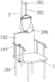
the support device comprises a base, wherein four support legs are welded on the lower surface of the base, a support seat is welded on the upper surface of the base, a first handrail and a second handrail are arranged on the upper surface of the base, a rotating rod is assembled between the first handrail and the base, and a limiting assembly is arranged at the top end of the rotating rod;
the movable rod, the movable rod sets up the back at the supporting seat, just the transmission assembly of assembly between movable rod and the dwang, the top welding of movable rod has the kicking block, the lower fixed surface of kicking block is connected with the connection rope, the bottom fixedly connected with fixed block of connecting the rope, the both sides of fixed block are all rotated and are connected with the connecting strip, and the bottom of two connecting strips is all rotated and is connected with movable strip, is provided with the removal subassembly between two movable strips, and the bottom of two movable strips is provided with the fixed band.
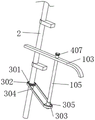
Preferably, two fixed rods are welded between the bottoms of the first handrail and the second handrail and the base, the first handrail and the second handrail are fixedly connected with the two sides of the supporting seat respectively, two supporting sleeves are movably sleeved on the outer surface of the movable rod, and the two supporting sleeves are fixedly connected to the back face of the supporting seat.
Preferably, the transmission assembly comprises a fixed sleeve, the upper surface of the fixed sleeve is welded on the lower surface of the base, the lower surface of the fixed sleeve is rotatably connected with a nut seat, and the inner wall of the nut seat is in threaded connection with the movable rod.
Preferably, the transmission assembly further comprises a first chain wheel and a second chain wheel, the first chain wheel and the second chain wheel are respectively and fixedly sleeved on the outer surface of the nut seat and the bottom end of the rotating rod, a chain is connected between the first chain wheel and the second chain wheel in a transmission mode, a fixed shaft sleeve is rotatably connected to the outer surface of the rotating rod, and the fixed shaft sleeve is fixedly connected to the lower surface of the base.
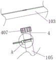
Preferably, the limiting assembly comprises a rotating block, the bottom end of the rotating block is movably inserted into the first handrail, the top end of the rotating block is fixedly connected with a handle, the bottom end of the rotating block is fixedly connected with a rectangular block, the top end of the rotating rod is movably inserted into the first handrail, the top end of the rotating rod is provided with a rectangular groove, the rectangular block is connected into the rectangular groove in a sliding mode, and the outer surface of the rectangular block is fixedly sleeved with an extrusion ring.
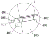
Preferably, spacing subassembly still includes the arc piece, arc piece sliding connection is in the inside of first handrail, just the arc piece closely laminates with the top of dwang, the last fixed surface of arc piece is connected with the extrusion piece, just the extrusion piece laminates with the extrusion ring mutually.
Preferably, the side wall of the extrusion block is fixedly connected with a telescopic rod and a limiting spring, the other ends of the telescopic rod and the limiting spring are fixedly connected to the inner wall of the first handrail, and the limiting spring is sleeved on the outer surface of the telescopic rod.
Preferably, the movable assembly comprises a fixed frame, the fixed frame is arranged under the fixed block, the end parts of the two movable strips are connected to the inner wall of the fixed frame in a sliding mode, the inner wall of the fixed frame is connected with a first rack and a second rack in a sliding mode, the first rack and the second rack are respectively fixedly connected with the end parts of the two movable strips, the first rack and the second rack are meshed with the transmission gear, the transmission rod is fixedly inserted into the inner wall of the transmission gear, the transmission rod is connected with the inner wall of the fixed frame in a rotating mode, and the bottom end of the transmission rod penetrates through the bottom wall of the fixed frame and extends downwards and is fixedly connected with the knob.
Preferably, the removal subassembly still includes the bearer bar, bearer bar fixed connection is at the upper surface of fixed frame, the roof that fixed frame was passed on the top of transfer line extends towards the inside of bearer bar to fixed cover has cup jointed stop gear, stop gear meshing is connected with the arc tooth piece, fixedly connected with pull rod on the lateral wall of arc tooth piece, the pull rod passes the lateral wall of bearer bar and outwards extends, reset spring has been cup jointed to the surface of pull rod, just reset spring's both ends difference fixed connection is on the lateral wall of arc tooth piece and the inner wall of bearer bar.
The invention discloses vertical traction physiotherapy equipment for cervical vertebra rehabilitation, which has the following beneficial effects:
1. this physiotherapy equipment is pull perpendicularly for cervical vertebra rehabilitation, transmission assembly through setting up, when the dwang rotates, the second sprocket that has driven its bottom rotates, first sprocket and nut seat have been driven through the chain and have begun to rotate simultaneously, because of nut seat and movable rod threaded connection, thereby the slow rebound of movable rod has been driven, the kicking block rebound has been pulled and has upwards pulled fixed band and patient's head through connecting the rope, until pulling suitable height to the patient, apply suitable dynamics, stall, the position to fixed band and patient's head is fixed, patient's cervical vertebra receives suitable traction force this moment, patient adjusts and finds suitable traction force more easily.
2. This physiotherapy equipment is pull perpendicularly to cervical vertebra rehabilitation, spacing subassembly through setting up, loosen the handle, telescopic link and the spacing spring bounce-back of compressing so far, it removes towards the top of extrusion ring and dwang respectively to have promoted extrusion piece and arc piece, the extrusion ring rebound has been promoted, make its inner wall with first handrail laminate mutually, make the top surface of arc piece and dwang closely laminate simultaneously, thereby fix the position of dwang, thereby avoided the dwang to receive rotating under the effect of external force, it reciprocates to have driven the fixed band, cause the condition of damage to the patient.
3. This physiotherapy equipment is pull perpendicularly for cervical vertebra rehabilitation, removal subassembly through setting up, the transfer line rotates, thereby it rotates to have driven drive gear, and then it slides in the opposite direction to have driven first rack and second rack, it perhaps moves back to back mutually to have driven two movable strips, it rotates to have driven two connecting strips, the distance of the one end that carries on the back mutually until two movable strips slightly is less than the diameter of patient's head, when pulling the fixed band cover on the head this moment, the fixed band has played fine laminating effect to the head, also can not excessively extrude the discomfort that causes the head simultaneously.
Drawings
FIG. 1 is a schematic structural view of the present invention;
FIG. 2 is a schematic view of a portion of the present invention;
FIG. 3 is a schematic bottom view of the present invention;
FIG. 4 is a schematic structural view of the transmission assembly of the present invention;
FIG. 5 is a schematic structural view of a stop assembly according to the present invention;
FIG. 6 is an enlarged view of portion A of FIG. 5 according to the present invention;
FIG. 7 is a schematic structural view of the joint of the fixing band and the top block of the present invention;
FIG. 8 is a schematic view of the moving assembly of the present invention;
fig. 9 is an enlarged view of the portion B of fig. 8 according to the present invention.
In the figure: 1. a base; 101. supporting legs; 102. a supporting seat; 103. a first armrest; 104. a second handrail; 105. rotating the rod; 106. fixing the rod; 2. a movable rod; 201. a top block; 202. connecting ropes; 203. a fixed block; 204. a connecting strip; 205. a movable bar; 206. fixing belts; 207. a support sleeve; 3. fixing a sleeve; 301. a nut seat; 302. a first sprocket; 303. a second sprocket; 304. a chain; 305. fixing the shaft sleeve; 4. rotating the block; 401. a rectangular block; 402. an extrusion ring; 403. an arc-shaped block; 404. extruding the block; 405. a telescopic rod; 406. a limiting spring; 407. a handle; 5. a fixing frame; 501. a first rack; 502. a second rack; 503. a transmission gear; 504. a transmission rod; 505. a protective frame; 506. a limit gear; 507. an arc-shaped tooth block; 508. a pull rod; 509. a return spring.
Detailed Description
The first embodiment is as follows:
the embodiment of the invention discloses a vertical traction physiotherapy device for cervical vertebra rehabilitation,
referring to fig. 1 and 7, including:
the support structure comprises a base 1, wherein four support legs 101 are welded on the lower surface of the base 1, a support seat 102 is welded on the upper surface of the base 1, a first handrail 103 and a second handrail 104 are arranged on the upper surface of the base 1, a rotating rod 105 is assembled between the first handrail 103 and the base 1, and a limiting assembly is arranged at the top end of the rotating rod 105;
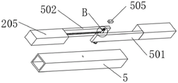
the movable rod 2, the movable rod 2 sets up the back at supporting seat 102, and the transmission assembly of assembly between movable rod 2 and dwang 105, the top welding of movable rod 2 has kicking block 201, the lower fixed surface of kicking block 201 is connected with and is connected rope 202, the bottom fixedly connected with fixed block 203 of connecting rope 202, the both sides of fixed block 203 are all rotated and are connected with connecting strip 204, the bottom of two connecting strips 204 is all rotated and is connected with movable strip 205, be provided with the removal subassembly between two movable strips 205, and the bottom of two movable strips 205 is provided with fixed band 206.
Referring to fig. 2, two fixing rods 106 are welded between the bottoms of the first handrail 103 and the second handrail 104 and the base 1, the first handrail 103 and the second handrail 104 are respectively and fixedly connected with two sides of the supporting seat 102, two supporting sleeves 207 are movably sleeved on the outer surface of the movable rod 2, and the two supporting sleeves 207 are fixedly connected to the back of the supporting seat 102.
Referring to fig. 3, the transmission assembly includes a fixing sleeve 3, an upper surface of the fixing sleeve 3 is welded on a lower surface of the base 1, a nut seat 301 is rotatably connected to the lower surface of the fixing sleeve 3, and an inner wall of the nut seat 301 is in threaded connection with the movable rod 2.
Referring to fig. 4, the transmission assembly further includes a first sprocket 302 and a second sprocket 303, the first sprocket 302 and the second sprocket 303 are respectively and fixedly sleeved on the outer surface of the nut base 301 and the bottom end of the rotating rod 105, a chain 304 is connected between the first sprocket 302 and the second sprocket 303 in a transmission manner, a fixed bushing 305 is rotatably connected on the outer surface of the rotating rod 105, and the fixed bushing 305 is fixedly connected on the lower surface of the base 1.
Referring to fig. 5 and 6, the limiting assembly includes a rotating block 4, the bottom end of the rotating block 4 is movably inserted into the first handrail 103, the top end of the rotating block 4 is fixedly connected with a handle 407, the bottom end of the rotating block 4 is fixedly connected with a rectangular block 401, the top end of the rotating rod 105 is movably inserted into the first handrail 103, a rectangular groove is formed in the top end of the rotating rod 105, the rectangular block 401 is slidably connected into the rectangular groove, and an extrusion ring 402 is sleeved on the outer surface of the rectangular block 401.
The limiting assembly further comprises an arc-shaped block 403, the arc-shaped block 403 is slidably connected inside the first handrail 103, the arc-shaped block 403 is tightly attached to the top end of the rotating rod 105, an extrusion block 404 is fixedly connected to the upper surface of the arc-shaped block 403, and the extrusion block 404 is attached to the extrusion ring 402.
The side wall of the extrusion block 404 is fixedly connected with an expansion link 405 and a limit spring 406, the other ends of the expansion link 405 and the limit spring 406 are fixedly connected to the inner wall of the first handrail 103, and the limit spring 406 is sleeved on the outer surface of the expansion link 405.
The working principle is as follows: in the using process, firstly, the fixing band 206 is sleeved on the head, so that the lower jaw is attached to the fixing band 206, then the handle 407 is pressed downwards to drive the rotating block 4 to move towards the inside of the first handrail 103, the rectangular block 401 and the extrusion ring 402 are pushed to move downwards simultaneously, the rectangular block 401 slides downwards in the rectangular groove, the extrusion ring 402 extrudes the extrusion block 404, the extrusion block 404 moves transversely, the telescopic rod 405 and the limiting spring 406 are compressed, the arc-shaped block 403 is driven to be separated from the outer surface of the top end of the rotating rod 105, at the moment, the handle 407 is rotated, the rotating rod 105 is driven to rotate through the rectangular block 401, and the extrusion ring 402 rubs against the extrusion block 404 to rotate;
when the rotating rod 105 rotates, the second chain wheel 303 at the bottom end of the rotating rod is driven to rotate, the first chain wheel 302 and the nut seat 301 are driven to simultaneously rotate through the chain 304, and the nut seat 301 is in threaded connection with the movable rod 2, so that the movable rod 2 is driven to slowly move upwards, the jacking block 201 is pulled to move upwards and the fixing band 206 and the head of the patient are pulled upwards through the connecting rope 202 until the patient is pulled to a proper height, a proper force is applied, the rotation is stopped, the fixing band 206 and the head of the patient are fixed, the cervical vertebra of the patient is subjected to a proper traction force, and the patient adjusts to find the proper traction force more easily;
at this time, the handle 407 is loosened, the telescopic rod 405 and the limiting spring 406 which are compressed before rebound, the extrusion block 404 and the arc block 403 are pushed to move towards the top ends of the extrusion ring 402 and the rotating rod 105 respectively, the extrusion ring 402 is pushed to move upwards to be attached to the inner wall of the first handrail 103, and meanwhile, the arc block 403 is closely attached to the outer surface of the top end of the rotating rod 105, so that the position of the rotating rod 105 is fixed, the rotating rod 105 is prevented from rotating under the action of external force, the fixing belt 206 is driven to move up and down, and the patient is prevented from being damaged;
after the traction is finished, the handle 407 is pressed downwards again to repeat the above actions, the handle 407 is rotated reversely, the movable rod 2 moves downwards slowly, the fixing belt 206 is driven to move downwards, and at the moment, the patient can dismount the fixing belt 206.
Example two:
the embodiment of the invention discloses a vertical traction physiotherapy device for cervical vertebra rehabilitation,
referring to fig. 1 and 7, including:
the support structure comprises a base 1, wherein four support legs 101 are welded on the lower surface of the base 1, a support seat 102 is welded on the upper surface of the base 1, a first handrail 103 and a second handrail 104 are arranged on the upper surface of the base 1, a rotating rod 105 is assembled between the first handrail 103 and the base 1, and a limiting assembly is arranged at the top end of the rotating rod 105;
the movable rod 2, the movable rod 2 sets up the back at supporting seat 102, and the transmission assembly of assembly between movable rod 2 and dwang 105, the top welding of movable rod 2 has kicking block 201, the lower fixed surface of kicking block 201 is connected with and is connected rope 202, the bottom fixedly connected with fixed block 203 of connecting rope 202, the both sides of fixed block 203 are all rotated and are connected with connecting strip 204, the bottom of two connecting strips 204 is all rotated and is connected with movable strip 205, be provided with the removal subassembly between two movable strips 205, and the bottom of two movable strips 205 is provided with fixed band 206.
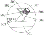
Referring to fig. 7-9, the moving assembly includes a fixed frame 5, the fixed frame 5 is disposed under the fixed block 203, the ends of the two movable bars 205 are slidably connected to the inner wall of the fixed frame 5, the inner wall of the fixed frame 5 is slidably connected to a first rack 501 and a second rack 502, the first rack 501 and the second rack 502 are respectively fixedly connected to the ends of the two movable bars 205, the first rack 501 and the second rack 502 are engaged with a transmission gear 503, a transmission rod 504 is fixedly inserted into the inner wall of the transmission gear 503, the transmission rod 504 is rotatably connected to the inner wall of the fixed frame 5, and the bottom end of the transmission rod 504 penetrates through the bottom wall of the fixed frame 5 to extend downward and is fixedly connected to a knob.
The movable assembly further comprises a protection frame 505, the protection frame 505 is fixedly connected to the upper surface of the fixed frame 5, the top end of the transmission rod 504 penetrates through the top wall of the fixed frame 5 and extends towards the inside of the protection frame 505, a limit gear 506 is fixedly sleeved and connected with the limit gear 506, the limit gear 506 is meshed and connected with an arc-shaped tooth block 507, a pull rod 508 is fixedly connected to the side wall of the arc-shaped tooth block 507, the pull rod 508 penetrates through the side wall of the protection frame 505 and extends outwards, a reset spring 509 is sleeved on the outer surface of the pull rod 508, and two ends of the reset spring 509 are respectively and fixedly connected to the side wall of the arc-shaped tooth block 507 and the inner wall of the protection frame 505.
According to the working principle, in the using process, firstly, according to the size of the head of a patient, the pull rod 508 is pulled outwards, the arc-shaped tooth block 507 is driven to move towards the direction away from the limit gear 506, the arc-shaped tooth block is separated from the limit gear 506, the return spring 509 is compressed, the knob is rotated at the moment, the transmission rod 504 is driven to rotate, so that the transmission gear 503 is driven to rotate, the first rack 501 and the second rack 502 are meshed with the transmission gear 503 to be connected, the first rack 501 and the second rack 502 are driven to slide in opposite directions, the two movable strips 205 are driven to move towards or away from each other, the two connecting strips 204 are driven to rotate, and the distance between the back-to-back ends of the two movable strips 205 is slightly smaller than the diameter of the head of the patient;
at this time, the pull rod 508 is loosened, the return spring 509 rebounds to push the arc-shaped tooth block 507 to move towards the direction of the limit gear 506 and is attached to the limit gear 506 so as to fix the positions of the limit gear 506 and the transmission rod 504, and further fix the positions of the first rack 501, the second rack 502, the transmission gear 503 and the two movable strips 205;
when the fixing band 206 is sleeved on the head to be pulled, the fixing band 206 has a good fitting effect on the head, and the head cannot be discomforted due to excessive extrusion.
In summary, the following steps: in the using process, firstly, according to the size of the head of a patient, the pull rod 508 is pulled outwards, the arc-shaped tooth block 507 is driven to move towards the direction away from the limit gear 506, the arc-shaped tooth block is separated from the limit gear 506, the return spring 509 is compressed, the knob is rotated at the moment, the transmission rod 504 is driven to rotate, so that the transmission gear 503 is driven to rotate, the first rack 501 and the second rack 502 are meshed with the transmission gear 503 to be connected, the first rack 501 and the second rack 502 are driven to slide in opposite directions, the two movable strips 205 are driven to move towards or away from each other, and the two connecting strips 204 are driven to rotate until the distance between the opposite ends of the two movable strips 205 is slightly smaller than the diameter of the head of the patient;
at this time, the pull rod 508 is loosened, the return spring 509 rebounds to push the arc-shaped tooth block 507 to move towards the direction of the limit gear 506 and is attached to the limit gear 506 so as to fix the positions of the limit gear 506 and the transmission rod 504, and further fix the positions of the first rack 501, the second rack 502, the transmission gear 503 and the two movable strips 205;
at this time, the fixing band 206 is sleeved on the head, so that the lower jaw is attached to the fixing band 206, then the handle 407 is pressed downwards to drive the rotating block 4 to move towards the inside of the first handrail 103, so that the rectangular block 401 and the extrusion ring 402 are pushed to move downwards simultaneously, the rectangular block 401 slides downwards in the rectangular groove, the extrusion ring 402 extrudes the extrusion block 404, the extrusion block 404 moves transversely, the telescopic rod 405 and the limiting spring 406 are compressed, the arc-shaped block 403 is driven to be separated from the outer surface of the top end of the rotating rod 105, the handle 407 is rotated, the rotating rod 105 is driven to rotate through the rectangular block 401, and the extrusion ring 402 rubs against the extrusion block 404 to rotate;
when the rotating rod 105 rotates, the second chain wheel 303 at the bottom end of the rotating rod is driven to rotate, the first chain wheel 302 and the nut seat 301 are driven to simultaneously rotate through the chain 304, and the nut seat 301 is in threaded connection with the movable rod 2, so that the movable rod 2 is driven to slowly move upwards, the jacking block 201 is pulled to move upwards and the fixing band 206 and the head of the patient are pulled upwards through the connecting rope 202 until the patient is pulled to a proper height, a proper force is applied, the rotation is stopped, the fixing band 206 and the head of the patient are fixed, the cervical vertebra of the patient is subjected to a proper traction force, and the patient adjusts to find the proper traction force more easily;
at this time, the handle 407 is loosened, the telescopic rod 405 and the limiting spring 406 which are compressed before rebound, the extrusion block 404 and the arc block 403 are pushed to move towards the top ends of the extrusion ring 402 and the rotating rod 105 respectively, the extrusion ring 402 is pushed to move upwards to be attached to the inner wall of the first handrail 103, and meanwhile, the arc block 403 is closely attached to the outer surface of the top end of the rotating rod 105, so that the position of the rotating rod 105 is fixed, the rotating rod 105 is prevented from rotating under the action of external force, the fixing belt 206 is driven to move up and down, and the patient is prevented from being damaged;
after the traction is finished, the handle 407 is pressed downwards again to repeat the above actions, the handle 407 is rotated reversely, the movable rod 2 moves downwards slowly, the fixing belt 206 is driven to move downwards, and at the moment, the patient can dismount the fixing belt 206.
The foregoing shows and describes the general principles and broad features of the present invention and advantages thereof. It will be understood by those skilled in the art that the present invention is not limited to the embodiments described above, which are described in the specification and illustrated only to illustrate the principle of the present invention, but that various changes and modifications may be made therein without departing from the spirit and scope of the present invention, which fall within the scope of the invention as claimed. The scope of the invention is defined by the appended claims and equivalents thereof.
Claims (9)
1. The utility model provides a vertical traction physiotherapy equipment that cervical vertebra rehabilitation used which characterized in that includes:
the support structure comprises a base (1), wherein four supporting legs (101) are welded on the lower surface of the base (1), a supporting seat (102) is welded on the upper surface of the base (1), a first handrail (103) and a second handrail (104) are arranged on the upper surface of the base (1), a rotating rod (105) is assembled between the first handrail (103) and the base (1), and a limiting assembly is arranged at the top end of the rotating rod (105);
movable rod (2), movable rod (2) set up the back at supporting seat (102), just the transmission assembly of assembly between movable rod (2) and dwang (105), the top welding of movable rod (2) has kicking block (201), the lower fixed surface of kicking block (201) is connected rope (202), the bottom fixedly connected with fixed block (203) of connecting rope (202), the both sides of fixed block (203) all rotate and are connected with connecting strip (204), and the bottom of two connecting strips (204) all rotates and is connected with movable strip (205), is provided with the removal subassembly between two movable strips (205), and the bottom of two movable strips (205) is provided with fixed band (206).
2. The vertical traction physiotherapy apparatus for cervical vertebra rehabilitation according to claim 1, wherein: two fixing rods (106) are welded between the bottoms of the first handrail (103) and the second handrail (104) and the base (1), the first handrail (103) and the second handrail (104) are fixedly connected with the two sides of the supporting seat (102) respectively, two supporting sleeves (207) are movably sleeved on the outer surface of the movable rod (2), and the two supporting sleeves (207) are fixedly connected to the back of the supporting seat (102).
3. The vertical traction physiotherapy apparatus for cervical vertebra rehabilitation according to claim 1, wherein: the transmission assembly comprises a fixed sleeve (3), the upper surface of the fixed sleeve (3) is welded on the lower surface of the base (1), the lower surface of the fixed sleeve (3) is rotatably connected with a nut seat (301), and the inner wall of the nut seat (301) is in threaded connection with the movable rod (2).
4. The vertical traction physiotherapy apparatus for cervical vertebra rehabilitation according to claim 3, wherein: the transmission assembly further comprises a first chain wheel (302) and a second chain wheel (303), the first chain wheel (302) and the second chain wheel (303) are respectively fixedly sleeved on the outer surface of the nut seat (301) and the bottom end of the rotating rod (105), a chain (304) is connected between the first chain wheel (302) and the second chain wheel (303) in a transmission mode, the outer surface of the rotating rod (105) is rotatably connected with a fixed shaft sleeve (305), and the fixed shaft sleeve (305) is fixedly connected to the lower surface of the base (1).
5. The vertical traction physiotherapy apparatus for cervical vertebra rehabilitation according to claim 1, wherein: spacing subassembly includes turning block (4), the inside at first handrail (103) is pegged graft in the bottom activity of turning block (4), the top fixedly connected with handle (407) of turning block (4), the bottom fixedly connected with rectangular block (401) of turning block (4), the top activity of dwang (105) is pegged graft in the inside of first handrail (103), and the top of dwang (105) has seted up the rectangular channel, rectangular block (401) sliding connection in the rectangular channel, extrusion ring (402) has been cup jointed to the external fixed surface of rectangular block (401).
6. The vertical traction physiotherapy apparatus for cervical vertebra rehabilitation according to claim 5, wherein: spacing subassembly still includes arc piece (403), arc piece (403) sliding connection is in the inside of first handrail (103), just arc piece (403) closely laminates with the top of dwang (105), the last fixed surface of arc piece (403) is connected with extrusion piece (404), just extrusion piece (404) laminate mutually with extrusion ring (402).
7. The vertical traction physiotherapy apparatus for cervical vertebra rehabilitation according to claim 6, wherein: the side wall of the extrusion block (404) is fixedly connected with an expansion link (405) and a limiting spring (406), the other ends of the expansion link (405) and the limiting spring (406) are fixedly connected to the inner wall of the first handrail (103), and the limiting spring (406) is sleeved on the outer surface of the expansion link (405).
8. The vertical traction physiotherapy apparatus for cervical vertebra rehabilitation according to claim 1, wherein: the movable assembly comprises a fixed frame (5), the fixed frame (5) is arranged under the fixed block (203), the end parts of two movable strips (205) are connected to the inner wall of the fixed frame (5) in a sliding mode, the inner wall of the fixed frame (5) is connected with a first rack (501) and a second rack (502) in a sliding mode, the first rack (501) and the second rack (502) are respectively fixedly connected with the end parts of the two movable strips (205), the first rack (501) and the second rack (502) are connected with a transmission gear (503) in a meshing mode, a transmission rod (504) is fixedly inserted into the inner wall of the transmission gear (503) in a plugging mode, the transmission rod (504) is rotatably connected with the inner wall of the fixed frame (5), and the bottom end of the transmission rod (504) penetrates through the bottom wall of the fixed frame (5) to extend downwards and is fixedly connected with a knob.
9. The vertical traction physiotherapy apparatus for cervical vertebra rehabilitation according to claim 8, wherein: the movable assembly further comprises a protection frame (505), the protection frame (505) is fixedly connected to the upper surface of the fixed frame (5), the top end of the transmission rod (504) penetrates through the top wall of the fixed frame (5) and extends towards the inside of the protection frame (505), a limiting gear (506) is fixedly sleeved on the top wall of the transmission rod (504), an arc-shaped tooth block (507) is meshed and connected with the limiting gear (506), a pull rod (508) is fixedly connected to the side wall of the arc-shaped tooth block (507), the pull rod (508) penetrates through the side wall of the protection frame (505) and extends outwards, a reset spring (509) is sleeved on the outer surface of the pull rod (508), and the two ends of the reset spring (509) are fixedly connected to the side wall of the arc-shaped tooth block (507) and the inner wall of the protection frame (505) respectively.
Priority Applications (1)
| Application Number | Priority Date | Filing Date | Title |
|---|---|---|---|
| CN202110615532.6A CN113288548A (en) | 2021-06-02 | 2021-06-02 | Vertical traction physiotherapy equipment for cervical vertebra rehabilitation |
Applications Claiming Priority (1)
| Application Number | Priority Date | Filing Date | Title |
|---|---|---|---|
| CN202110615532.6A CN113288548A (en) | 2021-06-02 | 2021-06-02 | Vertical traction physiotherapy equipment for cervical vertebra rehabilitation |
Publications (1)
| Publication Number | Publication Date |
|---|---|
| CN113288548A true CN113288548A (en) | 2021-08-24 |
Family
ID=77326921
Family Applications (1)
| Application Number | Title | Priority Date | Filing Date |
|---|---|---|---|
| CN202110615532.6A Withdrawn CN113288548A (en) | 2021-06-02 | 2021-06-02 | Vertical traction physiotherapy equipment for cervical vertebra rehabilitation |
Country Status (1)
| Country | Link |
|---|---|
| CN (1) | CN113288548A (en) |
Citations (15)
| Publication number | Priority date | Publication date | Assignee | Title |
|---|---|---|---|---|
| US5560577A (en) * | 1994-06-24 | 1996-10-01 | Allen Medical Systems | Adjustable limb support system |
| CN205903340U (en) * | 2016-06-08 | 2017-01-25 | 北京鼎云升科技有限公司 | Novel cervical vertebra tractor |
| US20170049655A1 (en) * | 2014-02-14 | 2017-02-23 | Tae-Soo SUNG | Chair having neck exercise support for neck exercise |
| CN107456303A (en) * | 2017-09-15 | 2017-12-12 | 陈慧 | A kind of medical cervical stretching chair that can adjust height of seat |
| JP6396557B1 (en) * | 2017-09-08 | 2018-09-26 | Dipperホクメイ株式会社 | handrail |
| CN109172352A (en) * | 2018-09-10 | 2019-01-11 | 潍坊学院 | A kind of cervical vertebra rehabilitation chair |
| CN208864601U (en) * | 2018-03-13 | 2019-05-17 | 吕岩 | A kind of leg in traction device of orthopaedics detection sliding positioning |
| CN209203670U (en) * | 2018-08-21 | 2019-08-06 | 周云 | A kind of household prevention and treatment cervical spondylosis traction frame |
| CN209825920U (en) * | 2019-05-08 | 2019-12-24 | 河北助邦医疗设备有限公司 | Office traction dual-purpose chair |
| CN110830111A (en) * | 2018-08-09 | 2020-02-21 | 江苏慧丰信息科技有限公司 | Wireless communication LED lamp of installation and dismantlement |
| CN211087322U (en) * | 2020-03-17 | 2020-07-24 | 广州滕炕贸易有限公司 | Attendance checking equipment for enterprise management |
| CN111853050A (en) * | 2020-07-01 | 2020-10-30 | 张国辉 | Movable joint device of support frame |
| CN112353399A (en) * | 2020-11-11 | 2021-02-12 | 王芳 | Mobile electrocardiograph with portable structure |
| CN112603481A (en) * | 2020-12-18 | 2021-04-06 | 常州安康医疗器械有限公司 | Visual puncture outfit convenient to fixed gas-supply pipe |
| CN212938928U (en) * | 2020-04-21 | 2021-04-13 | 黑河学院 | External Chinese teaching is with extending chair |
-
2021
- 2021-06-02 CN CN202110615532.6A patent/CN113288548A/en not_active Withdrawn
Patent Citations (15)
| Publication number | Priority date | Publication date | Assignee | Title |
|---|---|---|---|---|
| US5560577A (en) * | 1994-06-24 | 1996-10-01 | Allen Medical Systems | Adjustable limb support system |
| US20170049655A1 (en) * | 2014-02-14 | 2017-02-23 | Tae-Soo SUNG | Chair having neck exercise support for neck exercise |
| CN205903340U (en) * | 2016-06-08 | 2017-01-25 | 北京鼎云升科技有限公司 | Novel cervical vertebra tractor |
| JP6396557B1 (en) * | 2017-09-08 | 2018-09-26 | Dipperホクメイ株式会社 | handrail |
| CN107456303A (en) * | 2017-09-15 | 2017-12-12 | 陈慧 | A kind of medical cervical stretching chair that can adjust height of seat |
| CN208864601U (en) * | 2018-03-13 | 2019-05-17 | 吕岩 | A kind of leg in traction device of orthopaedics detection sliding positioning |
| CN110830111A (en) * | 2018-08-09 | 2020-02-21 | 江苏慧丰信息科技有限公司 | Wireless communication LED lamp of installation and dismantlement |
| CN209203670U (en) * | 2018-08-21 | 2019-08-06 | 周云 | A kind of household prevention and treatment cervical spondylosis traction frame |
| CN109172352A (en) * | 2018-09-10 | 2019-01-11 | 潍坊学院 | A kind of cervical vertebra rehabilitation chair |
| CN209825920U (en) * | 2019-05-08 | 2019-12-24 | 河北助邦医疗设备有限公司 | Office traction dual-purpose chair |
| CN211087322U (en) * | 2020-03-17 | 2020-07-24 | 广州滕炕贸易有限公司 | Attendance checking equipment for enterprise management |
| CN212938928U (en) * | 2020-04-21 | 2021-04-13 | 黑河学院 | External Chinese teaching is with extending chair |
| CN111853050A (en) * | 2020-07-01 | 2020-10-30 | 张国辉 | Movable joint device of support frame |
| CN112353399A (en) * | 2020-11-11 | 2021-02-12 | 王芳 | Mobile electrocardiograph with portable structure |
| CN112603481A (en) * | 2020-12-18 | 2021-04-06 | 常州安康医疗器械有限公司 | Visual puncture outfit convenient to fixed gas-supply pipe |
Similar Documents
| Publication | Publication Date | Title |
|---|---|---|
| CN111054032B (en) | Wearable wrist rehabilitation nursing exercise device | |
| CN107296720B (en) | Multifunctional walking training machine for hemiplegic rehabilitation | |
| CN111135015A (en) | A rehabilitation training device for knee joint | |
| CN113577676B (en) | Rehabilitation therapy apparatus for muscle strength decline and using method thereof | |
| CN111000700A (en) | Rehabilitation and nursing equipment for leg joint exercise | |
| CN113288548A (en) | Vertical traction physiotherapy equipment for cervical vertebra rehabilitation | |
| CN210301390U (en) | Multifunctional knee joint cold compress pressurizing fixing device | |
| CN211326222U (en) | Department of general surgery's nursing device | |
| CN215231875U (en) | Clinical exercise device of traditional chinese medical science cardiovascular internal medicine | |
| CN108403278B (en) | Spinal correction device capable of achieving bidirectional stretching for surgery | |
| CN113749904A (en) | Special rehabilitation apparatus of elbow for orthopedics | |
| CN112618130A (en) | Medical lumbar traction bed | |
| CN112932759A (en) | Pediatric orthopedic traction device capable of preventing skin damage | |
| CN212416282U (en) | Orthopedic patient limb rehabilitation exercise device | |
| CN216023002U (en) | Device is tempered to children's nursing shank | |
| CN220370392U (en) | Limb rehabilitation auxiliary training device | |
| CN115300859B (en) | Auxiliary training device and method for training waist flexibility and abdomen strength | |
| CN216168385U (en) | Medical instrument for leg rehabilitation of patient with sickbed lying | |
| CN219042866U (en) | Leg support for wound orthopaedics postoperative recovery | |
| CN219307853U (en) | Rehabilitation apparatus for limb postoperative exercise | |
| CN212308376U (en) | Medical treatment is recovered to help outfit for a journey to put | |
| CN219681597U (en) | Upper limb rehabilitation exercise robot | |
| CN219983388U (en) | Lower limb massager | |
| CN218740068U (en) | Knee joint rehabilitation training device | |
| CN217938636U (en) | Device for postoperative heel sliding rehabilitation training of hip fracture patient |
Legal Events
| Date | Code | Title | Description |
|---|---|---|---|
| PB01 | Publication | ||
| PB01 | Publication | ||
| SE01 | Entry into force of request for substantive examination | ||
| SE01 | Entry into force of request for substantive examination | ||
| WW01 | Invention patent application withdrawn after publication | ||
| WW01 | Invention patent application withdrawn after publication |
Application publication date: 20210824 |