CN113277318A - Long-range pneumatic conveying system of mining material - Google Patents
Long-range pneumatic conveying system of mining material Download PDFInfo
- Publication number
- CN113277318A CN113277318A CN202110558794.3A CN202110558794A CN113277318A CN 113277318 A CN113277318 A CN 113277318A CN 202110558794 A CN202110558794 A CN 202110558794A CN 113277318 A CN113277318 A CN 113277318A
- Authority
- CN
- China
- Prior art keywords
- dust
- flow guide
- dust removal
- gas
- feeding
- Prior art date
- Legal status (The legal status is an assumption and is not a legal conclusion. Google has not performed a legal analysis and makes no representation as to the accuracy of the status listed.)
- Granted
Links
- 239000000463 material Substances 0.000 title claims abstract description 83
- 238000005065 mining Methods 0.000 title claims description 17
- 239000000428 dust Substances 0.000 claims abstract description 129
- 239000000203 mixture Substances 0.000 claims description 13
- 230000000149 penetrating effect Effects 0.000 claims description 2
- 230000005540 biological transmission Effects 0.000 abstract description 4
- 238000007599 discharging Methods 0.000 abstract description 2
- 230000002349 favourable effect Effects 0.000 abstract 1
- 238000000034 method Methods 0.000 description 9
- 241000273930 Brevoortia tyrannus Species 0.000 description 2
- 230000009286 beneficial effect Effects 0.000 description 2
- 238000010276 construction Methods 0.000 description 2
- 238000005516 engineering process Methods 0.000 description 2
- 238000001914 filtration Methods 0.000 description 2
- XLYOFNOQVPJJNP-UHFFFAOYSA-N water Substances O XLYOFNOQVPJJNP-UHFFFAOYSA-N 0.000 description 2
- 238000001816 cooling Methods 0.000 description 1
- 230000007547 defect Effects 0.000 description 1
- 238000010586 diagram Methods 0.000 description 1
- 238000001035 drying Methods 0.000 description 1
- 230000000694 effects Effects 0.000 description 1
- 239000012530 fluid Substances 0.000 description 1
- 238000005243 fluidization Methods 0.000 description 1
- 239000008187 granular material Substances 0.000 description 1
- 238000010438 heat treatment Methods 0.000 description 1
- 239000002245 particle Substances 0.000 description 1
- 239000000126 substance Substances 0.000 description 1
- 239000013589 supplement Substances 0.000 description 1
Images



Classifications
-
- B—PERFORMING OPERATIONS; TRANSPORTING
- B65—CONVEYING; PACKING; STORING; HANDLING THIN OR FILAMENTARY MATERIAL
- B65G—TRANSPORT OR STORAGE DEVICES, e.g. CONVEYORS FOR LOADING OR TIPPING, SHOP CONVEYOR SYSTEMS OR PNEUMATIC TUBE CONVEYORS
- B65G53/00—Conveying materials in bulk through troughs, pipes or tubes by floating the materials or by flow of gas, liquid or foam
- B65G53/04—Conveying materials in bulk pneumatically through pipes or tubes; Air slides
-
- B—PERFORMING OPERATIONS; TRANSPORTING
- B65—CONVEYING; PACKING; STORING; HANDLING THIN OR FILAMENTARY MATERIAL
- B65G—TRANSPORT OR STORAGE DEVICES, e.g. CONVEYORS FOR LOADING OR TIPPING, SHOP CONVEYOR SYSTEMS OR PNEUMATIC TUBE CONVEYORS
- B65G53/00—Conveying materials in bulk through troughs, pipes or tubes by floating the materials or by flow of gas, liquid or foam
- B65G53/34—Details
-
- B—PERFORMING OPERATIONS; TRANSPORTING
- B65—CONVEYING; PACKING; STORING; HANDLING THIN OR FILAMENTARY MATERIAL
- B65G—TRANSPORT OR STORAGE DEVICES, e.g. CONVEYORS FOR LOADING OR TIPPING, SHOP CONVEYOR SYSTEMS OR PNEUMATIC TUBE CONVEYORS
- B65G69/00—Auxiliary measures taken, or devices used, in connection with loading or unloading
- B65G69/18—Preventing escape of dust
- B65G69/181—Preventing escape of dust by means of sealed systems
Landscapes
- Engineering & Computer Science (AREA)
- Mechanical Engineering (AREA)
- Filtering Of Dispersed Particles In Gases (AREA)
- Air Transport Of Granular Materials (AREA)
Abstract
The invention discloses a remote pneumatic conveying system for mine materials, which comprises a plurality of bins, wherein a feeding unit and a dust removal unit are respectively arranged on the bins, and the feeding unit enters the bins after being subjected to dust removal through the dust removal unit; the feeding unit comprises a feeding box and a feeding gas pipeline which are arranged on the outer wall of the storage bin, one end of the feeding box is provided with a connecting flange, and the other end of the feeding box is communicated with the feeding gas pipeline, is mixed with the feeding gas pipeline and is communicated with the interior of the dust removal unit; the dust removal unit comprises a dust removal cover and a filter material structure arranged in the dust removal cover, and the dust and gas are separated from the material by the filter material structure of the mine material mixed by the feeding box and the feeding gas transmission pipeline, so that the dust and gas are discharged out of the bin through the dust removal cover; in the dust excluding covers respectively positioned on the plurality of bins, every two adjacent dust excluding covers are connected through a dust excluding pipe. The dust and gas discharging device can discharge dust and gas out of the bin during feeding, prevents the dust and gas from being transported into a pipeline, and is favorable for preventing the pipeline from being blocked.
Description
Technical Field
The invention relates to a mine material conveying device, in particular to a mine material remote pneumatic conveying system.
Background
The pneumatic conveying is to convey granular material in the direction of air flow in a closed pipeline by utilizing the energy of the air flow, and is a specific application of fluidization technology. The pneumatic conveying device has simple structure and convenient operation, can be used for horizontal, vertical or inclined conveying, and can simultaneously carry out physical operations or certain chemical operations such as heating, cooling, drying, airflow classification and the like on materials in the conveying process. The pneumatic conveying is mainly characterized by large conveying capacity, long conveying distance and high conveying speed; it is possible to charge at one location and then discharge at multiple locations. Due to the characteristics of pneumatic conveying, the pneumatic conveying is widely applied to the transportation of mining materials.
However, when the materials are conveyed, because the materials can generate a large amount of dust and gas in the feeding process, if the materials are directly conveyed, the closed pipeline can be blocked, and the materials are not easy to convey.
Disclosure of Invention
In order to solve the defects in the prior art, the invention aims to provide a remote pneumatic conveying system for mine materials, which can discharge dust gas out of a bin during feeding, prevent the dust gas from being conveyed into a pipeline and is beneficial to preventing the pipeline from being blocked.
The technical scheme adopted by the invention for solving the technical problems is as follows: a remote pneumatic conveying system for mine materials comprises a plurality of bins, wherein a feeding unit and a dust removal unit are respectively arranged on the bins, and the feeding unit enters the bins after being subjected to dust removal through the dust removal unit;
the feeding unit comprises a feeding box and a feeding gas pipeline which are arranged on the outer wall of the storage bin, one end of the feeding box is provided with a connecting flange, and the other end of the feeding box is communicated with the feeding gas pipeline, is mixed with the feeding gas pipeline and is communicated with the interior of the dust removal unit;
the dust removal unit comprises a dust removal cover and a filter material structure arranged in the dust removal cover, and the dust and gas are separated from the material by the filter material structure of the mine material mixed by the feeding box and the feeding gas transmission pipeline, so that the dust and gas are discharged out of the bin through the dust removal cover;
and in the dust hoods respectively positioned on the plurality of bins, every two adjacent dust hoods are connected through a dust removal pipe.
Optionally, the filter material structure includes the inlet pipe, the end connection of inlet pipe has the kuppe for the mixture of dirt gas and material passes through the kuppe separates.
Optionally, a first conical flow guide part is arranged inside the flow guide cover, a flow guide cover is arranged on the upper part of the flow guide cover, and the top height of the first flow guide part is lower than the cover body height of the flow guide cover;
the tail end of the feeding pipe penetrates through the guide cover and then extends to the upper side of the first guide part towards the inside of the guide cover.
Optionally, a gap is formed between the flow guide cover and the flow guide cover, so that a flow guide channel is formed between the flow guide cover and the flow guide cover;
a plurality of circles of impact parts are arranged in the flow guide channel, so that the mixture of the material and the dust gas collides with the impact parts when passing through the flow guide channel.
Optionally, an opening at the tail end of the flow guide channel faces downwards, so that the tail end of the flow guide channel forms a material falling guide portion, and a second flow guide portion for guiding the dust gas to the upper portion of the dust hood is further arranged at the tail end of the flow guide channel.
Optionally, the tail end of the flow guide channel is inclined, so that the dust and air flows out of the flow guide channel along the flow guide channel in an inclined and downward manner.
Optionally, the dust removal unit further comprises a dust removal gas input mechanism, wherein a gas outlet of the dust removal gas input mechanism is located inside the dust hood, and a gas outlet of the dust removal gas input mechanism is located below the tail end of the flow guide channel.
Optionally, a conical cylinder is connected to a gas outlet of the dedusting gas input mechanism, a gas outlet penetrating through the inside and the outside of the conical cylinder is formed in the conical cylinder, and an axis of the gas outlet is parallel to an axis of the conical cylinder.
Optionally, the axis of the conical cylinder coincides with the axis of the dust hood.
Optionally, the inside of dust excluding hood is still fixedly connected with vortex formula water conservancy diversion mechanism in the top position that is located the filter material structure, and the dirt gas passes through vortex formula water conservancy diversion mechanism carries out the pressure release.
By adopting the technical scheme, compared with the prior art, the invention has the following beneficial effects:
1. according to the remote pneumatic conveying system for the mining materials, the dust gas generated in the feeding process is discharged out of the stock bin through the dust removing unit, so that the dust gas can be effectively prevented from entering the interior of the stock bin, and further, the dust gas is prevented from entering a pipeline in the material conveying process;
2. according to the remote pneumatic conveying system for the mining materials, the dust removal units on the plurality of bin units are connected through the dust removal pipes, so that the dust removal capacity of the dust removal units can be effectively improved in the dust removal process.
Drawings
FIG. 1 is a schematic structural view of the present invention;
FIG. 2 is a schematic view of the construction of the dust removing unit of the present invention;
FIG. 3 is a schematic structural view of a filter media construction of the present invention;
fig. 4 is a schematic structural diagram of the vortex type flow guiding mechanism of the present invention.
Detailed Description
The present application will be described in further detail with reference to the following drawings and examples. It is to be understood that the specific embodiments described herein are merely illustrative of the relevant invention and not restrictive of the invention. It should be noted that, for convenience of description, only the portions related to the present invention are shown in the drawings.
It should be noted that the embodiments and features of the embodiments in the present application may be combined with each other without conflict. The present application will be described in detail below with reference to the embodiments with reference to the attached drawings.
As shown in fig. 1, the invention discloses a remote pneumatic conveying system for mining materials, which comprises a plurality of bins 1, wherein a feeding unit and a dust removal unit are respectively arranged on the bins 1, and the feeding unit enters the interior of the bin 1 after being subjected to dust removal by the dust removal unit so as to remove dust and gas generated in the feeding process of the materials and prevent the dust and gas from entering a conveying pipeline. According to the invention, by using the plurality of bins 1, continuous conveying can be realized during material conveying, namely after the material in one bin 1 is conveyed, the other bin 1 can be switched to for conveying, and the conveyed bin 1 can be supplemented with the material so as to facilitate the next material conveying. Therefore, in the present invention, the number of the bunkers 1 is at least two, but the number is not too large due to the limitation of the size of the chamber, for example, in one embodiment of the present invention, the number of the bunkers 1 can be set to four to meet the requirement of material transportation.
Specifically, in the invention, the feeding unit comprises a feeding box 2 and a feeding gas pipeline 3 which are arranged on the outer wall of the storage bin 1, one end of the feeding box 2 is provided with a connecting flange, and the other end of the feeding box is communicated with the feeding gas pipeline 3, mixed and then communicated with the interior of the dust removal unit. The invention supplements the materials to be conveyed into the storage bin 1 through the feeding unit.
Wherein, the air supply system (not shown in the figure) is connected to the one end of material loading gas transmission pipeline 3, and the other end is worn into feed bin 1 interior back, is connected with the discharge end of material loading case 2, makes material and material loading gas mixture form the gas-material mixture, then reconnects to dust removal unit, and dust removal unit removes dust to the gas-material mixture after, the material is thrown into the inside of feed bin 1 and is saved.
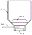
In the invention, as shown in fig. 2, the dust removal unit comprises a dust removal cover 4 and a filter material structure 5 arranged in the dust removal cover 4, and the dust and gas are separated from the material by the filter material structure 5 after the material loading box 2 and the material loading gas pipeline 3 are mixed, so that the dust and gas are discharged out of the bin 1 through the dust removal cover 4. In the invention, because the storage bins 1 are operated under pressure in the feeding process, the working pressure of the dust removal units is high, the flow speed is high, and because the height of the chamber is limited, the adopted dust removal covers 4 are not too high to prevent the reduction of the dust removal capacity of the dust removal units, therefore, in the invention, every two adjacent dust removal covers 4 in the dust removal covers 4 respectively positioned on the storage bins 1 are connected through the dust removal pipe 6, so that a multi-body communicated dust remover is formed among the dust removal units, and the dust removal area is increased after the dust removal covers 4 are connected through the dust removal pipes 6, thereby improving the dust removal efficiency.
In the invention, because the grain diameter and the weight of the mining materials are generally larger than those of dust, the filter material structure 5 is used for filtering the materials and allowing dust and gas to pass through, thereby achieving the effect of the filter material. Specifically, as shown in fig. 3, the filter material structure 5 includes a feeding pipe 501, and a diversion cover 502 is connected to the end of the feeding pipe 501, so that the mixture of dust gas and material is separated by the diversion cover 502. In addition, the feeding gas transmission pipeline 3 is connected with the feeding pipe 501 after being connected with the discharging end of the feeding box 2, so that the gas-material mixture enters the feeding pipe 501.
The air guide sleeve 502 is internally provided with a first tapered air guide part 503, the upper part of the air guide sleeve 502 is provided with an air guide cover 504, the top height of the first air guide part 503 is lower than the cover height of the air guide sleeve 502, and the tail end of the feed pipe 501 penetrates through the air guide cover 504 and then extends to the upper part of the first air guide part 503 towards the inside of the air guide sleeve 502.
When the first flow guide part 503 is provided, the first flow guide part 503 and the flow guide cover 502 are integrally formed, specifically, the first flow guide part 503 extends upwards from the center of the bottom of the flow guide cover 502, an annular groove 509 is formed between the bottom of the first flow guide part 503 and the bottom of the flow guide cover 502, and the bottom of the groove 509 is of an arc structure, that is, the cross section of the groove 509 is of an arc structure. The two side walls of the groove 509 are inclined, that is, the inner side wall of the dome 502 is inclined, so as to guide the gas-material mixture to the direction of the dome 504. In the present invention, the groove 509 is provided to consume the kinetic energy of the material, and to guide the gas-material mixture into the flow guide channel 505.
A gap is formed between the pod 504 and the pod 502, such that a flow guide channel 505 is formed between the pod 502 and the pod 504. The multi-circle impact part 506 is arranged in the flow guide channel 505, the heights of the impact parts 506 are sequentially increased from inside to outside, so that the mixture of the material and the dust gas collides with the impact parts 506 when passing through the flow guide channel 505, through the arrangement of the impact parts 506, the material collides with the impact parts 506 in the movement process of the gas-material mixture, kinetic energy is gradually consumed, the moving capacity of the material along with the air flow is reduced, and the kinetic energy consumed by the dust is insufficient to overcome the fluid pressure of the air flow due to small particle size and light weight, and the dust can continuously move along with the movement of the air flow, and in the process, the material and the dust are separated.
In the present invention, the opening of the end of the flow guide channel 505 faces downward, so that the end of the flow guide channel 505 constitutes a material falling guide part 507, and the end of the flow guide channel 505 is further provided with a second flow guide part 508 for guiding the dust and air above the dust hood 4. The end of the flow guide channel 505 is inclined, so that the dust and air flows out of the flow guide channel 505 along the flow guide channel 505.
In the present invention, the dust removing unit further comprises a dust removing gas input mechanism 7, wherein the gas outlet of the dust removing gas input mechanism 7 is located inside the dust removing cover 4, and the gas outlet of the dust removing gas input mechanism 7 is located below the tail end of the flow guide channel 505. The dust gas from the diversion channel 505 is guided by the dust gas input mechanism 7, and then guided to the upper part of the filter material structure 5, and then enters the dust removal pipe 6 to be discharged out of the dust hood 4.
In the invention, the outlet position of the dedusting gas input mechanism 7 is connected with a conical cylinder 8, the conical cylinder 8 is provided with an outlet hole 801 which penetrates through the inside and the outside of the conical cylinder 8, the axis of the outlet hole 801 is parallel to the axis of the conical cylinder 8, and the axis of the conical cylinder 8 is superposed with the axis of the dedusting cover 4. Through the arrangement of the conical barrel 8, the falling materials can be guided. In addition, in order to prevent the material from falling into the air outlet 801 to block the air outlet 801, a filter screen may be installed outside the air outlet 801.
As shown in fig. 2, a vortex type flow guide mechanism 9 is further fixedly connected to the inside of the dust hood 4 above the filter material structure 5, and the dust is decompressed through the vortex type flow guide mechanism 9. As shown in fig. 4, the vortex flow guide mechanism 9 includes a conical flow guide cylinder 901, a plurality of uniformly distributed guide vanes 902 are mounted on an inner wall of the flow guide cylinder 901, and the guide vanes 902 are obliquely mounted on the inner wall of the flow guide cylinder 901. The large diameter end of the draft tube 901 is arranged towards the filtering material structure 5 to guide the dust and air.
The above description is only a preferred embodiment of the application and is illustrative of the principles of the technology employed. It will be appreciated by a person skilled in the art that the scope of the invention as referred to in the present application is not limited to the embodiments with a specific combination of the above-mentioned features, but also covers other embodiments with any combination of the above-mentioned features or their equivalents without departing from the inventive concept. For example, the above features may be replaced with (but not limited to) features having similar functions disclosed in the present application.
Other technical features than those described in the specification are known to those skilled in the art, and are not described herein in detail in order to highlight the innovative features of the present invention.
Claims (10)
1. The remote pneumatic conveying system for the mining materials is characterized by comprising a plurality of bins (1), wherein a feeding unit and a dust removal unit are respectively arranged on the bins (1), and the feeding unit enters the bins (1) after being subjected to dust removal through the dust removal unit;
the feeding unit comprises a feeding box (2) and a feeding gas pipeline (3) which are arranged on the outer wall of the storage bin (1), one end of the feeding box (2) is provided with a connecting flange, and the other end of the feeding box is communicated and mixed with the feeding gas pipeline (3) and then communicated with the interior of the dust removal unit;
the dust removal unit comprises a dust removal cover (4) and a filter material structure (5) arranged in the dust removal cover (4), and the dust and gas of the mine material mixed by the feeding box (2) and the feeding gas pipeline (3) are separated from the material through the filter material structure (5), so that the dust and gas are discharged out of the bin (1) through the dust removal cover (4);
in the dust removal covers (4) respectively positioned on the plurality of bins (1), every two adjacent dust removal covers (4) are connected through a dust removal pipe (6).
2. The remote pneumatic conveying system for mining materials according to claim 1, wherein the filter material structure (5) comprises a feeding pipe (501), and a flow guide cover (502) is connected to the tail end of the feeding pipe (501) so that the mixture of dust gas and materials is separated through the flow guide cover (502).
3. The mining material remote pneumatic conveying system according to claim 2, wherein a first conical flow guide part (503) is arranged inside the flow guide cover (502), a flow guide cover (504) is arranged on the upper part of the flow guide cover (502), and the height of the top of the first flow guide part (503) is lower than the height of the cover body of the flow guide cover (502);
the tail end of the feeding pipe (501) penetrates through the diversion cover (504) and then extends to the interior of the diversion cover (502) to the position above the first diversion part (503).
4. The mining material remote pneumatic conveying system according to claim 3, wherein a gap is formed between the deflector cap (504) and the deflector cap (502) so that a deflector channel (505) is formed between the deflector cap (502) and the deflector cap (504);
a plurality of circles of impact parts (506) are arranged in the flow guide channel (505), so that the mixture of the materials and the dust and the air collides with the impact parts (506) when passing through the flow guide channel (505).
5. The remote pneumatic conveying system for mining materials according to claim 4, characterized in that the end opening of the flow guide channel (505) faces downwards, so that the end of the flow guide channel (505) constitutes a material falling guide (507), and the end of the flow guide channel (505) is further provided with a second flow guide (508) for guiding the dust gas above the dust hood (4).
6. The mining material remote pneumatic conveying system according to claim 5, wherein the end of the flow guide channel (505) is inclined, so that dust and air flow out of the flow guide channel (505) along the flow guide channel (505) in an inclined downward manner.
7. The mining material remote pneumatic conveying system according to claim 6, wherein the dust removal unit further comprises a dust removal gas input mechanism (7), the gas outlet of the dust removal gas input mechanism (7) is located inside the dust hood (4), and the gas outlet of the dust removal gas input mechanism (7) is located below the end of the diversion channel (505).
8. The mining material remote pneumatic conveying system according to claim 7, wherein a conical cylinder (8) is connected to a gas outlet of the dedusting gas input mechanism (7), a gas outlet hole (801) penetrating through the inside and the outside of the conical cylinder (8) is formed in the conical cylinder (8), and the axis of the gas outlet hole (801) is parallel to the axis of the conical cylinder (8).
9. The mining material remote pneumatic conveying system according to claim 8, characterized in that the axis of the conical cylinder (8) coincides with the axis of the dust hood (4).
10. The mining material remote pneumatic conveying system according to claim 9, wherein a vortex type flow guide mechanism (9) is further fixedly connected to the inside of the dust hood (4) above the filter material structure (5), and dust and air are decompressed through the vortex type flow guide mechanism (9).
Priority Applications (1)
| Application Number | Priority Date | Filing Date | Title |
|---|---|---|---|
| CN202110558794.3A CN113277318B (en) | 2021-05-21 | 2021-05-21 | Long-range pneumatic conveying system of mining material |
Applications Claiming Priority (1)
| Application Number | Priority Date | Filing Date | Title |
|---|---|---|---|
| CN202110558794.3A CN113277318B (en) | 2021-05-21 | 2021-05-21 | Long-range pneumatic conveying system of mining material |
Publications (2)
| Publication Number | Publication Date |
|---|---|
| CN113277318A true CN113277318A (en) | 2021-08-20 |
| CN113277318B CN113277318B (en) | 2023-01-06 |
Family
ID=77280681
Family Applications (1)
| Application Number | Title | Priority Date | Filing Date |
|---|---|---|---|
| CN202110558794.3A Active CN113277318B (en) | 2021-05-21 | 2021-05-21 | Long-range pneumatic conveying system of mining material |
Country Status (1)
| Country | Link |
|---|---|
| CN (1) | CN113277318B (en) |
Citations (9)
| Publication number | Priority date | Publication date | Assignee | Title |
|---|---|---|---|---|
| EP2412652A1 (en) * | 2010-07-26 | 2012-02-01 | Pelletron Corporation | Pneumatic conveying system for particulate materials |
| CN203110150U (en) * | 2013-01-17 | 2013-08-07 | 天津市鑫泉龙建筑混凝土有限公司 | Bunker dust collector of mixing station |
| US20150110565A1 (en) * | 2010-12-03 | 2015-04-23 | Jack Harris | System for delivering solid particulate matter for loading |
| CN206050963U (en) * | 2016-08-10 | 2017-03-29 | 山西兰花华明纳米材料股份有限公司 | The pneumatic conveyer of nano-calcium carbonate filter cake material |
| CN108163551A (en) * | 2017-12-08 | 2018-06-15 | 北京神雾电力科技有限公司 | Low order fine coal air-transport system |
| CN207532993U (en) * | 2017-10-24 | 2018-06-26 | 福建优晟饲料有限公司 | A kind of tandem dust-extraction unit |
| CN210763171U (en) * | 2019-08-12 | 2020-06-16 | 郑州市高原耐火材料有限公司 | Intelligent refractory material conveying system |
| CN112193837A (en) * | 2020-09-24 | 2021-01-08 | 淮南东华欧科矿山支护设备有限责任公司 | Self-induction constant-pressure mining material remote pneumatic conveying system |
| CN212767756U (en) * | 2020-06-23 | 2021-03-23 | 河南万美新型建材有限公司 | Novel dustproof stock bin jar |
-
2021
- 2021-05-21 CN CN202110558794.3A patent/CN113277318B/en active Active
Patent Citations (9)
| Publication number | Priority date | Publication date | Assignee | Title |
|---|---|---|---|---|
| EP2412652A1 (en) * | 2010-07-26 | 2012-02-01 | Pelletron Corporation | Pneumatic conveying system for particulate materials |
| US20150110565A1 (en) * | 2010-12-03 | 2015-04-23 | Jack Harris | System for delivering solid particulate matter for loading |
| CN203110150U (en) * | 2013-01-17 | 2013-08-07 | 天津市鑫泉龙建筑混凝土有限公司 | Bunker dust collector of mixing station |
| CN206050963U (en) * | 2016-08-10 | 2017-03-29 | 山西兰花华明纳米材料股份有限公司 | The pneumatic conveyer of nano-calcium carbonate filter cake material |
| CN207532993U (en) * | 2017-10-24 | 2018-06-26 | 福建优晟饲料有限公司 | A kind of tandem dust-extraction unit |
| CN108163551A (en) * | 2017-12-08 | 2018-06-15 | 北京神雾电力科技有限公司 | Low order fine coal air-transport system |
| CN210763171U (en) * | 2019-08-12 | 2020-06-16 | 郑州市高原耐火材料有限公司 | Intelligent refractory material conveying system |
| CN212767756U (en) * | 2020-06-23 | 2021-03-23 | 河南万美新型建材有限公司 | Novel dustproof stock bin jar |
| CN112193837A (en) * | 2020-09-24 | 2021-01-08 | 淮南东华欧科矿山支护设备有限责任公司 | Self-induction constant-pressure mining material remote pneumatic conveying system |
Also Published As
| Publication number | Publication date |
|---|---|
| CN113277318B (en) | 2023-01-06 |
Similar Documents
| Publication | Publication Date | Title |
|---|---|---|
| CN100512942C (en) | Method and device for adjustment solid cycle quantity of circulating fluidized bed reaction system | |
| CN101939235B (en) | Method and device for feeding fine-to coarse-grained solid particles into a container and for transferring them to a system at a higher pressure | |
| CN104399607B (en) | A kind of cyclone separator and the cyclone separation system based on the device | |
| CN113277318B (en) | Long-range pneumatic conveying system of mining material | |
| KR20100138983A (en) | Device for removing fine-grained or dust-like solids from a container | |
| CN111841842B (en) | Fly ash production system | |
| US4934281A (en) | Circulating fluidized bed reactor and a method of separating solid material from flue gases | |
| CN106606999B (en) | Fluidized bed reactor | |
| CN102913271A (en) | Dust removal system for spraying machine | |
| CN201132137Y (en) | Horizontal tube type third stage cyclone separating device | |
| CN110272765A (en) | A kind of inertial separation deduster and dust removal method | |
| CN202866864U (en) | Pulp shooting machine dust-clearing system | |
| CN108543399A (en) | Electrical Equipments of Coal Mine chamber cleaning gas | |
| KR20190099421A (en) | Cyclone adapter | |
| KR20150110521A (en) | Dust catcher for blast furnace gas | |
| CN206398707U (en) | A kind of band loosens the feeding back device of wind backward | |
| JP5308224B2 (en) | Dust catcher for blast furnace gas | |
| CN104741254A (en) | Dust-containing scorched particle winnowing and separating device and method thereof | |
| CN109276955A (en) | A kind of method of coal dust feed bin and fine coal gas solid separation | |
| CN221028513U (en) | Combined gas purifying and recovering equipment | |
| CN1295120C (en) | Ventilation uniform petrochemical bunker | |
| CN210339204U (en) | Chute buffering connector and chute using same for wheat flour milling production line | |
| CN216189286U (en) | Powder conveying pipeline | |
| CN210339205U (en) | Chute for wheat flour milling production line and chute buffering connector thereof | |
| CN216727679U (en) | Falling wetting type pre-sorting device of non-pressure feeding dense medium cyclone |
Legal Events
| Date | Code | Title | Description |
|---|---|---|---|
| PB01 | Publication | ||
| PB01 | Publication | ||
| SE01 | Entry into force of request for substantive examination | ||
| SE01 | Entry into force of request for substantive examination | ||
| GR01 | Patent grant | ||
| GR01 | Patent grant | ||
| CP03 | Change of name, title or address | ||
| CP03 | Change of name, title or address |
Address after: 232072 Bagongshan Tofu Cultural Industrial Park, Bagongshan District, Huainan City, Anhui Province Patentee after: Anhui Jingyuan Technology Co.,Ltd. Country or region after: China Address before: 232072 Bagongshan Tofu Cultural Industrial Park, Bagongshan District, Huainan City, Anhui Province Patentee before: HUAINAN DONGHUA OUKE MINE SUPPORT EQUIPMENT Co.,Ltd. Country or region before: China |