CN113260236A - Heat dissipation device for general electrical equipment - Google Patents
Heat dissipation device for general electrical equipment Download PDFInfo
- Publication number
- CN113260236A CN113260236A CN202110752241.1A CN202110752241A CN113260236A CN 113260236 A CN113260236 A CN 113260236A CN 202110752241 A CN202110752241 A CN 202110752241A CN 113260236 A CN113260236 A CN 113260236A
- Authority
- CN
- China
- Prior art keywords
- cooling
- pipe
- circulation
- water
- fixedly connected
- Prior art date
- Legal status (The legal status is an assumption and is not a legal conclusion. Google has not performed a legal analysis and makes no representation as to the accuracy of the status listed.)
- Withdrawn
Links
Images


Classifications
-
- H—ELECTRICITY
- H05—ELECTRIC TECHNIQUES NOT OTHERWISE PROVIDED FOR
- H05K—PRINTED CIRCUITS; CASINGS OR CONSTRUCTIONAL DETAILS OF ELECTRIC APPARATUS; MANUFACTURE OF ASSEMBLAGES OF ELECTRICAL COMPONENTS
- H05K7/00—Constructional details common to different types of electric apparatus
- H05K7/20—Modifications to facilitate cooling, ventilating, or heating
- H05K7/20009—Modifications to facilitate cooling, ventilating, or heating using a gaseous coolant in electronic enclosures
- H05K7/20136—Forced ventilation, e.g. by fans
-
- H—ELECTRICITY
- H05—ELECTRIC TECHNIQUES NOT OTHERWISE PROVIDED FOR
- H05K—PRINTED CIRCUITS; CASINGS OR CONSTRUCTIONAL DETAILS OF ELECTRIC APPARATUS; MANUFACTURE OF ASSEMBLAGES OF ELECTRICAL COMPONENTS
- H05K7/00—Constructional details common to different types of electric apparatus
- H05K7/20—Modifications to facilitate cooling, ventilating, or heating
- H05K7/20218—Modifications to facilitate cooling, ventilating, or heating using a liquid coolant without phase change in electronic enclosures
-
- H—ELECTRICITY
- H05—ELECTRIC TECHNIQUES NOT OTHERWISE PROVIDED FOR
- H05K—PRINTED CIRCUITS; CASINGS OR CONSTRUCTIONAL DETAILS OF ELECTRIC APPARATUS; MANUFACTURE OF ASSEMBLAGES OF ELECTRICAL COMPONENTS
- H05K7/00—Constructional details common to different types of electric apparatus
- H05K7/20—Modifications to facilitate cooling, ventilating, or heating
- H05K7/2039—Modifications to facilitate cooling, ventilating, or heating characterised by the heat transfer by conduction from the heat generating element to a dissipating body
Abstract
The invention discloses a heat sink for general electric equipment, comprising: the cooling device comprises an outer cooling pipe and an inner cooling pipe, wherein the outer cooling pipe is fixedly connected to the top of the inner cooling pipe, outer cooling fan blades are rotatably arranged inside the outer cooling pipe, and a mounting plate is fixedly connected to the surface of the inner cooling pipe; interior cooling subassembly sets up in the inside of cooling tube and is used for driving the interior air flow of electrical equipment. The spiral cooling fan blades are arranged on the outer side of the cooling cavity, the inner cooling fan blades are arranged on the inner side of the spiral cooling cavity, the outer cooling fan blades are arranged on the inner side of the spiral cooling cavity, and the inner cooling fan blades are connected with the outer cooling fan blades in a rotating mode.
Description
Technical Field
The invention relates to the technical field of heat dissipation of electrical equipment, in particular to a heat dissipation device for general electrical equipment.
Background
Electrical equipment is a general term for equipment such as generators, transformers, power lines, and circuit breakers in power systems. The important role played by electric power in our life and production is not ignored, brings great convenience to our life, and becomes an important energy source in our production and life. The most critical factor for normal operation and transmission of electric power in a power plant is that the electric equipment is provided with through holes on the surface when the electric equipment is cooled, and the external air is exchanged with high-temperature air in the electric equipment to achieve the purpose of cooling.
However, in the prior art, when the electric equipment is cooled in actual use, dust is easy to agglutinate and settle around the electric equipment, so that the insulation strength of the electric equipment is damaged, an electric breakdown short-circuit accident is easy to cause in the gas operation process, and some dust is accumulated in an electronic board to cause electric misoperation, short circuit and the like, thereby causing great harm to the safe operation of the electric equipment.
Disclosure of Invention
The present invention is directed to a heat dissipation device for general electrical equipment, which solves the above problems.
In order to achieve the purpose, the invention provides the following technical scheme: the method comprises the following steps:
the cooling device comprises an outer cooling pipe and an inner cooling pipe, wherein the outer cooling pipe is fixedly connected to the top of the inner cooling pipe, outer cooling fan blades are rotatably arranged inside the outer cooling pipe, and a mounting plate is fixedly connected to the surface of the inner cooling pipe;
the inner cooling assembly is arranged inside the inner cooling pipe and used for driving air in the electrical equipment to flow, the inner cooling assembly comprises an exhaust fan blade, a transmission rod and an inner cooling fan blade, and the inner cooling fan blade is fixedly connected to the surface of the transmission rod;
the water-cooling circulation assembly is arranged inside the side wall of the outer cooling fan blade and used for driving cooling liquid to circulate, the water-cooling circulation assembly comprises a circulation groove, the inner wall of the circulation groove is rotatably connected with a rotating pipe, and the surface of the rotating pipe is fixedly connected with a helical blade;
the driving assembly is arranged in the inner cooling pipe and is used for driving the rotating pipe, the outer cooling fan blades, the exhaust fan blades and the inner cooling fan blades to rotate and driving the inner cooling fan blades to revolve;
the water-cooling assembly is arranged at the bottom of the outer cooling fan blade and is used for carrying out heat exchange between cooling liquid and air in the electrical equipment, and the interior of the water-cooling assembly is communicated with the interior of the water-cooling circulation assembly;
the inner air heat dissipation circulation assembly is arranged inside the outer cooling fan blades and used for carrying out heat exchange between air in the electrical equipment and outside air.
Preferably, drive assembly includes the actuating lever, the surface of actuating lever is rotated through sealed bearing and is connected with the closing plate, and the inner wall of cooling tube including closing plate fixed connection, outer cooling flabellum and exhaust fan leaf fixed connection respectively are at the top and the bottom of actuating lever, the bottom fixedly connected with universal joint of actuating lever, and universal joint fixed connection is at the top of transfer line, a plurality of fresh air inlets have been seted up to the bottom on outer cooling tube surface.
Preferably, the surface of the driving rod is rotatably connected with a connecting frame through a bearing, the surface of the connecting frame is rotatably connected with a first circular truncated cone-shaped tooth column, an inner wall of the inner cooling pipe corresponding to the first circular truncated cone-shaped tooth column is fixedly connected with an inner gear ring, the cross section of the inner wall of the inner gear ring is of a trapezoidal structure, the inner wall of the inner gear ring is meshed with the surface of the first circular truncated cone-shaped tooth column, a second circular truncated cone-shaped tooth column is meshed with the surface of the first circular truncated cone-shaped tooth column, the second circular truncated cone-shaped tooth column is fixedly connected to the surface of the driving rod, the connecting frame is of an L-shaped structure, and the driving rod is rotatably connected to the bottom of the connecting frame through the bearing.
Preferably, the surface of the driving rod is fixedly connected with a first bevel gear, the surface of the first bevel gear is meshed with a second bevel gear, one end, far away from the first bevel gear, of the second bevel gear is fixedly connected with a driving gear, the surface of the driving gear is fixedly connected with a driving shaft, the surface of the driving shaft is movably provided with an outer gear ring, one end, corresponding to the driving shaft, of the outer gear ring is provided with a tooth socket, the inner wall of the tooth socket is meshed with the surface of the outer gear ring, the bottom of the outer gear ring is fixedly connected with a rotating ring, the rotating ring is fixedly connected to the inner wall of a rotating pipe, the inner wall, corresponding to the rotating ring, of the inner cooling pipe is provided with a movable groove, the inner wall of the movable groove is movably connected with the surface of the rotating ring, the inside of the movable groove is communicated with the inside of the circulating groove, and the driving gear movably penetrates through a bearing and extends to the outside of the inner cooling pipe, drive gear keeps away from the one end fixedly connected with driving motor of interior cooling tube position, and driving motor fixed connection is at the top of mounting panel, the inner wall fixedly connected with mount of outer cooling tube, and mount fixed connection is at the top of closing plate, the mount is L type structure, and actuating lever and drive gear equally divide and do not rotate the middle part of connecting at the mount through the bearing.
Preferably, the water-cooling circulation subassembly still includes first communicating hole and circulation chamber, the lateral wall of cooling pipe including first communicating hole and circulation chamber are all seted up, the inside of first communicating hole is linked together with the inside in circulation groove and circulation chamber respectively, the circulation chamber is helical structure, other fixedly connected with sealing washer is equallyd divide at the upper and lower both ends of rotating tube, the seal groove has been seted up to the inside of the corresponding sealing washer position of interior cooling pipe, and the inner wall of seal groove is rotated with the surface of sealing washer and is connected, the inside of seal groove is linked together with the inside of circulation groove.
Preferably, water-cooling subassembly includes the water-cooling circulating pipe, the both ends of water-cooling circulating pipe are equallyd divide do not with the lateral wall top and the bottom fixed connection of outer cooling flabellum, the inside of water-cooling circulating pipe one end is linked together with the inside in circulation chamber, and the one end of water-cooling circulating pipe is located the bottom in circulation chamber, the inside of the water-cooling circulating pipe other end is linked together with the inside in circulation groove, and the other end of water-cooling circulating pipe is located the top in circulation groove, the middle part fixedly connected with spiral pipe of water-cooling circulating pipe, the middle part fixedly connected with fin of spiral pipe, the fin is inside hollow structure, and the inside of fin is equipped with spiral water flow channel, the inside of spiral pipe is linked together with the inside of fin, the water-cooling circulating pipe is fixed to run through and extends to the upper and lower both ends of mounting panel.
Preferably, the inside of the side wall of the inner cooling pipe is also provided with an inner air heat dissipation circulation component, the inner air heat dissipation circulation component comprises a second communicating hole, an air outlet hole and a communicating cavity, the inside of the second communicating hole is respectively communicated with the inside of the air outlet hole and the inside of the communicating cavity, the inside of the air outlet hole is communicated with the inside of the outer cooling fan blade, the air outlet hole and the communicating cavity are arranged in a staggered mode, the surface of the inner cooling pipe is fixedly connected with an air circulation pipe, and the inside of one end of the air circulation pipe is communicated with the inside of the communicating cavity.
Preferably, air circulation pipe and water-cooling circulation pipe are all fixed and run through and extend to the both ends of mounting panel, the air inlet tank has been seted up to the bottom of mounting panel, and the air circulation pipe is kept away from the one end of outer cooling flabellum position and is linked together with the inside of air inlet tank, the corresponding outer cooling pipe position of air circulation pipe and water-cooling circulation pipe all is helical structure, and air circulation pipe helical structure is located water-cooling circulation pipe helical structure's outside.
Compared with the prior art, the invention has the beneficial effects that:
1. the spiral position of the water-cooling circulating pipe and the air circulating pipe is radiated by the external cooling fan blades, the air in the air circulating pipe exchanges heat with cooling liquid in the circulating cavity when passing through the communicating cavity, the second communicating hole and the air outlet hole and finally returns to the electrical equipment, and the spiral pipe and the radiating fins can uniformly radiate the air in the electrical equipment by matching with the rotation and revolution of the internal cooling fan blades, and the air in the electrical equipment is not exchanged with the external air, so that the aim of dust-free can be fulfilled under the condition of not affecting the radiation;
2. the invention also drives the driving gear to rotate through the work of the driving motor, and causes the driving gear to respectively drive the driving shaft and the second bevel gear to rotate, when the second bevel gear rotates, the second bevel gear drives the driving rod to rotate through the first bevel gear, and when the driving rod rotates, the driving rod drives the outer cooling fan blade and the exhaust fan blade to rotate, simultaneously the driving rod drives the inner cooling fan blade to rotate through the universal joint and the matching driving rod, and when the first circular table-shaped tooth column rotates, the driving rod drives the second circular table-shaped tooth column to rotate, further causes the second circular table-shaped tooth column to be meshed with the first circular table-shaped tooth column, and causes the first circular table-shaped tooth column to revolve around the inner wall of the inner gear ring while being meshed with the second circular table-shaped tooth column, thereby causing the first circular table-shaped tooth column to drive the driving rod through the connecting frame and using the driving rod as a rotating shaft, the inner cooling fan blades revolve while rotating; the drive shaft can drive outer ring gear when rotating, and then make outer ring gear drive and rotate the circle and rotate, and can drive the rotating tube when rotating the circle and rotate, and then make the rotating tube drive helical blade and rotate at the inner wall of circulation groove, because helical blade is helical structure, this just makes helical blade when rotating, can carry the liquid at circulation groove top to the bottom of circulation groove, and then for the rotating tube, outer cooling flabellum, the rotation of drawing fan leaf and interior cooling flabellum provides power.
Drawings
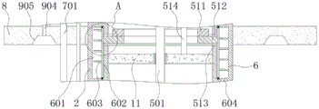
FIG. 1 is a front sectional view of an overall structure of a heat dissipating device for a general electric apparatus according to the present invention;
FIG. 2 is a partial cross-sectional side view of the overall structure of a heat sink for general electric equipment according to the present invention;
FIG. 3 is a front view of a water-cooling assembly of a heat dissipation device for general electric equipment according to the present invention;
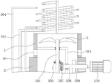
FIG. 4 is a partial front sectional view of the overall structure of a heat dissipating device for a general electrical apparatus according to the present invention;
FIG. 5 is a partial front sectional view of an inner cooling tube structure of a heat sink for a universal electrical device according to the present invention;
FIG. 6 is an enlarged view of the structure at the position A in FIG. 5 of the heat dissipating device for a general electrical apparatus according to the present invention;
fig. 7 is a front sectional view of an external cooling tube structure of a heat sink for general electrical equipment according to the present invention.
In the figure: 1. an outer cooling tube; 2. an inner cooling tube; 3. outer cooling fan blades; 4. an internal cooling assembly; 401. an extraction fan blade; 402. a transmission rod; 403. inner cooling fan blades; 5. a drive assembly; 501. a drive rod; 502. a connecting frame; 503. a first cone-shaped tooth column; 504. an inner gear ring; 505. a universal joint; 506. a first bevel gear; 507. a second bevel gear; 508. a drive gear; 509. a drive shaft; 510. a drive motor; 511. an outer ring gear; 512. rotating the ring; 513. a movable groove; 514. a fixed mount; 515. a second truncated cone-shaped tooth column; 6. a water-cooled circulation component; 601. a circulation tank; 602. rotating the tube; 603. a helical blade; 604. a first communication hole; 605. a circulation chamber; 606. a seal ring; 607. a sealing groove; 7. a water-cooled cooling assembly; 701. a water-cooled circulation pipe; 702. a spiral tube; 703. a heat sink; 8. mounting a plate; 9. an inner air heat dissipation cycle assembly; 901. a second communication hole; 902. an air outlet; 903. a communicating cavity; 904. an air circulation pipe; 905. an air inlet groove; 10. an air inlet hole; 11. and (7) sealing the plate.
Detailed Description
The technical solutions in the embodiments of the present invention will be clearly and completely described below with reference to the drawings in the embodiments of the present invention, and it is obvious that the described embodiments are only a part of the embodiments of the present invention, and not all of the embodiments. All other embodiments, which can be derived by a person skilled in the art from the embodiments given herein without making any creative effort, shall fall within the protection scope of the present invention.
Referring to fig. 1-7, the present invention provides a technical solution: the method comprises the following steps:
the cooling device comprises an outer cooling pipe 1 and an inner cooling pipe 2, wherein the outer cooling pipe 1 is fixedly arranged at the top of the inner cooling pipe 2, outer cooling fan blades 3 are rotatably arranged inside the outer cooling pipe 1, and a mounting plate 8 is fixedly arranged on the surface of the inner cooling pipe 2;
the inner cooling component 4 is arranged inside the inner cooling pipe 2 and is used for driving air in the electrical equipment to flow, the inner cooling component 4 comprises an exhaust fan blade 401, a transmission rod 402 and inner cooling fan blades 403, and the inner cooling fan blades 403 are fixedly arranged on the surface of the transmission rod 402;
the water-cooling circulation component 6 is arranged inside the side wall of the outer cooling fan blade 3 and is used for driving cooling liquid to circulate, the water-cooling circulation component 6 comprises a circulation groove 601, the inner wall of the circulation groove 601 is rotatably connected with a rotating pipe 602, and the surface of the rotating pipe 602 is fixedly provided with a helical blade 603;
the driving assembly 5 is arranged inside the inner cooling pipe 2 and is used for driving the rotating pipe 602, the outer cooling fan blades 3, the exhaust fan blades 401 and the inner cooling fan blades 403 to rotate and driving the inner cooling fan blades 403 to revolve;
the water-cooling component 7 is arranged at the bottom of the outer cooling fan blade 3 and is used for carrying out heat exchange between cooling liquid and air in the electrical equipment, and the inside of the water-cooling component 7 is communicated with the inside of the water-cooling circulation component 6;
and the inner air heat dissipation circulation assembly 9 is arranged inside the outer cooling fan blades 3 and is used for carrying out heat exchange between the air in the electrical equipment and the outside air.
Drive assembly 5 includes actuating lever 501, and actuating lever 501's surface is connected with closing plate 11 through sealed bearing rotation, and the inner wall of cooling tube 2 including closing plate 11 fixed mounting, outer cooling flabellum 3 and exhaust fan leaf 401 fixed mounting respectively in the top and the bottom of actuating lever 501, and the bottom fixed mounting of actuating lever 501 has universal joint 505, and universal joint 505 fixed mounting is at the top of transfer line 402, and a plurality of fresh air inlets 10 have been seted up to the bottom on outer cooling tube 1 surface.
The surface of the driving rod 501 is rotatably connected with a connecting frame 502 through a bearing, the surface of the connecting frame 502 is rotatably connected with a first circular truncated cone-shaped tooth column 503, the inner wall of the inner cooling pipe 2 corresponding to the position of the first circular truncated cone-shaped tooth column 503 is fixedly provided with an inner gear ring 504, the cross section of the inner wall of the inner gear ring 504 is of a trapezoidal structure, the inner wall of the inner gear ring 504 is meshed with the surface of the first circular truncated cone-shaped tooth column 503, the surface of the first circular truncated cone-shaped tooth column 503 is meshed with a second circular truncated cone-shaped tooth column 515, the second circular truncated cone-shaped tooth column 515 is fixedly arranged on the surface of the driving rod 501, the connecting frame 502 is of an L-shaped structure, and the driving rod 402 is rotatably connected to the bottom of the connecting frame 502 through a bearing.
A first bevel gear 506 is fixedly mounted on the surface of the driving rod 501, a second bevel gear 507 is meshed with the surface of the first bevel gear 506, a driving gear 508 is fixedly mounted at one end, far away from the first bevel gear 506, of the second bevel gear 507, a driving shaft 509 is fixedly mounted on the surface of the driving gear 508, an outer gear ring 511 is movably mounted on the surface of the driving shaft 509, a tooth socket is formed at one end, corresponding to the driving shaft 509, of the outer gear ring 511, the inner wall of the tooth socket is meshed with the surface of the outer gear ring 511, a rotating ring 512 is fixedly mounted at the bottom of the outer gear ring 511, the rotating ring 512 is fixedly mounted on the inner wall of the rotating pipe 602, a movable groove 513 is formed in the inner wall, corresponding to the rotating ring 512, of the inner cooling pipe 2, the inner wall of the movable groove 513 is movably connected with the surface of the rotating ring 512, the interior of the movable groove 513 is communicated with the interior of the circulating groove 601, and the driving gear 508 movably penetrates through a bearing and extends to the exterior of the inner cooling pipe 2, one end fixed mounting that interior cooling tube 2 position was kept away from to drive gear 508 has driving motor 510, and driving motor 510 fixed mounting is at the top of mounting panel 8, and the inner wall fixed mounting of outer cooling tube 1 has mount 514, and mount 514 fixed mounting is at the top of closing plate 11, and mount 514 is L type structure, and actuating lever 501 and drive gear 508 equally divide and do not rotate the middle part of connecting at mount 514 through the bearing.
The water-cooling circulation assembly 6 further comprises a first communicating hole 604 and a circulation cavity 605, the side wall of the inner cooling pipe 2 is formed by the first communicating hole 604 and the circulation cavity 605, the inside of the first communicating hole 604 is communicated with the inside of the circulation groove 601 and the inside of the circulation cavity 605 respectively, the circulation cavity 605 is of a spiral structure, the upper end and the lower end of the rotating pipe 602 are equally provided with a sealing ring 606 respectively, a sealing groove 607 is formed in the inside of the corresponding sealing ring 606 of the inner cooling pipe 2, the inner wall of the sealing groove 607 is rotatably connected with the surface of the sealing ring 606, and the inside of the sealing groove 607 is communicated with the inside of the circulation groove 601.
The water-cooling component 7 comprises a water-cooling circulating pipe 701, two ends of the water-cooling circulating pipe 701 are respectively and fixedly arranged with the top and the bottom of the side wall of the outer cooling fan blade 3, the inside of one end of the water-cooling circulating pipe 701 is communicated with the inside of the circulating cavity 605, and one end of the water-cooling circulation pipe 701 is positioned at the bottom of the circulation cavity 605, the inside of the other end of the water-cooling circulation pipe 701 is communicated with the inside of the circulation tank 601, the other end of the water-cooling circulating pipe 701 is positioned at the top of the circulating groove 601, the middle part of the water-cooling circulating pipe 701 is fixedly provided with a spiral pipe 702, the middle part of the spiral pipe 702 is fixedly provided with a radiating fin 703, the radiating fin 703 is of an internal hollow structure, and the inside of the cooling fin 703 is provided with a spiral water flow channel, the inside of the spiral pipe 702 is communicated with the inside of the cooling fin 703, the water-cooling circulating pipe 701 is fixedly penetrated and extends to the upper end and the lower end of the mounting plate 8, and the shape of the cooling fin 703 can be correspondingly changed according to the internal condition of the electrical equipment.
The inside of interior cooling tube 2's lateral wall still is equipped with interior air heat dissipation circulation subassembly 9, interior air heat dissipation circulation subassembly 9 includes second intercommunicating pore 901, venthole 902 and intercommunication chamber 903, the inside of second intercommunicating pore 901 is linked together with the inside of venthole 902 and intercommunication chamber 903 respectively, the inside of venthole 902 is linked together with the inside of outer cooling flabellum 3, and venthole 902 and circulation chamber 605 crisscross setting, the fixed surface of interior cooling tube 2 installs air circulation pipe 904, the inside of air circulation pipe 904 one end is linked together with the inside of intercommunication chamber 903.
The air circulation pipe 904 and the water-cooling circulation pipe 701 are fixedly penetrated and extend to two ends of the mounting plate 8, an air inlet groove 905 is formed in the bottom of the mounting plate 8, one end, away from the outer cooling fan blade 3, of the air circulation pipe 904 is communicated with the inside of the air inlet groove 905, the positions, corresponding to the outer cooling pipe 1, of the air circulation pipe 904 and the water-cooling circulation pipe 701 are both in spiral structures, and the spiral structures of the air circulation pipe 904 are located outside the spiral structures of the water-cooling circulation pipe 701.
The working principle is as follows: when the device is used, the driving motor 510 works to drive the driving gear 508 to rotate, the driving gear 508 drives the driving shaft 509 and the second bevel gear 507 to rotate respectively, when the second bevel gear 507 rotates, the second bevel gear 507 drives the driving rod 501 to rotate through the first bevel gear 506, when the driving rod 501 rotates, the driving rod 501 drives the outer cooling fan blades 3 and the exhaust fan blades 401 to rotate, meanwhile, the driving rod 501 drives the inner cooling fan blades 403 to rotate through the universal joint 505 and the driving rod 402, and when the first circular truncated cone-shaped column 503 rotates, the driving rod 501 drives the second circular truncated cone-shaped column 515 to rotate, so that the second circular truncated cone-shaped column 515 is meshed with the first circular truncated cone-shaped column 503, and the first circular truncated cone-shaped column 503 is meshed with the second circular truncated cone-shaped column 515 and revolves around the inner wall of the inner gear 504 while being matched with the inner gear 504, so that the first circular truncated cone-shaped tooth column 503 drives the transmission rod 402 to revolve around the driving rod 501 as a rotating shaft through the connecting frame 502, and the inner cooling fan blades 403 revolve while rotating; when the driving shaft 509 rotates, the outer gear ring 511 rotates, so that the outer gear ring 511 drives the rotating ring 512 to rotate, and when the rotating ring 512 rotates, the rotating pipe 602 rotates, so that the rotating pipe 602 drives the helical blade 603 to rotate on the inner wall of the circulating groove 601, because the helical blade 603 is of a helical structure, when the helical blade 603 rotates, the liquid on the top of the circulating groove 601 is conveyed to the bottom of the circulating groove 601, the cooling liquid in the circulating groove 601 is injected into the circulating cavity 605 through the first communication hole 604, and the cooling liquid flows around the side wall of the inner cooling pipe 2 in the circulating cavity 605, because the inside of one end of the water-cooling circulating pipe 701 is communicated with the inside of the circulating cavity 605, and one end of the water-cooling circulating pipe 701 is located at the bottom of the circulating cavity 605, the inside of the other end of the water-cooling circulating pipe 701 is communicated with the inside of the circulating groove 601, and the other end of the water-cooling circulating pipe 701 is located at the top of the circulating groove 601, when the fan blade 401 rotates, the fan blade 401 can generate negative pressure inside the inner cooling pipe 2, and the air inside the electrical equipment enters the air circulation pipe 904 through the air inlet slot 905, and the air inside the electrical equipment flows to the inside of the communication cavity 903 inside the air circulation pipe 904 through the air outlet hole 902 and the second communication hole 901, and because the air inside the electrical equipment passes through the spiral position in the middle of the air circulation pipe 904, the air in the spiral position of the air circulation pipe 904 can be radiated by the external cooling fan blade 3, the air in the electrical equipment can exchange heat with the cooling liquid circulated in the circulation cavity 605 through the air outlet 902 and the second communication hole 901, so that the air entering the internal cooling pipe 2 from the rotating pipe 602 is radiated, the air in the internal cooling pipe 2 is blown into the electrical equipment through the rotation of the exhaust fan blade 401 and the internal cooling fan blade 403, the air in the electrical equipment can be driven to flow due to the rotation and revolution of the internal cooling fan blade 403, so that the air temperature of the electrical equipment is more uniform, and the air exchanges heat with the spiral pipe 702 and the radiating fins 703 to achieve the purpose of radiating, the cooling liquid in the internal water cooling circulation pipe 701 passes through the spiral position of the water cooling circulation pipe 701 after completing the heat exchange with the air in the electrical equipment through the spiral pipe 702 and the radiating fins 703, and outside air is sucked by the outer cooling fan blades 3 to dissipate heat of air at the spiral position of the water-cooling circulating pipe 701, so that the purpose of dissipating heat of air in the electrical equipment is achieved, the air in the electrical equipment is not exchanged with the outside air, and the purpose of achieving dust-free under the condition of not affecting heat dissipation can be achieved.
It is noted that, herein, relational terms such as first and second, and the like may be used solely to distinguish one entity or action from another entity or action without necessarily requiring or implying any actual such relationship or order between such entities or actions. Also, the terms "comprises," "comprising," or any other variation thereof, are intended to cover a non-exclusive inclusion, such that a process, method, article, or apparatus that comprises a list of elements does not include only those elements but may include other elements not expressly listed or inherent to such process, method, article, or apparatus.
Although embodiments of the present invention have been shown and described, it will be appreciated by those skilled in the art that changes, modifications, substitutions and alterations can be made in these embodiments without departing from the principles and spirit of the invention, the scope of which is defined in the appended claims and their equivalents.
Claims (8)
1. A heat sink for general electric equipment, characterized in that: the method comprises the following steps:
the cooling device comprises an outer cooling pipe (1) and an inner cooling pipe (2), wherein the outer cooling pipe (1) is fixedly connected to the top of the inner cooling pipe (2), outer cooling fan blades (3) are rotatably arranged inside the outer cooling pipe (1), and a mounting plate (8) is fixedly connected to the surface of the inner cooling pipe (2);
the inner cooling component (4) is arranged inside the inner cooling pipe (2) and used for driving air in the electrical equipment to flow, the inner cooling component (4) comprises an exhaust fan blade (401), a transmission rod (402) and inner cooling fan blades (403), and the inner cooling fan blades (403) are fixedly connected to the surface of the transmission rod (402);
the water-cooling circulation assembly (6) is arranged inside the side wall of the outer cooling fan blade (3) and used for driving cooling liquid to circulate, the water-cooling circulation assembly (6) comprises a circulation groove (601), the inner wall of the circulation groove (601) is rotatably connected with a rotating pipe (602), and the surface of the rotating pipe (602) is fixedly connected with a helical blade (603);
the driving assembly (5) is arranged in the inner cooling pipe (2) and is used for driving the rotating pipe (602), the outer cooling fan blades (3), the exhaust fan blades (401) and the inner cooling fan blades (403) to rotate and driving the inner cooling fan blades (403) to revolve;
the water-cooling assembly (7) is arranged at the bottom of the outer cooling fan blade (3) and is used for carrying out heat exchange between cooling liquid and air in the electrical equipment, and the inside of the water-cooling assembly (7) is communicated with the inside of the water-cooling circulation assembly (6);
the internal air heat dissipation circulation assembly (9) is arranged inside the external cooling fan blades (3) and is used for carrying out heat exchange between the air in the electrical equipment and the external air.
2. The heat dissipating device for a general electric appliance according to claim 1, wherein: drive assembly (5) are including actuating lever (501), the surface of actuating lever (501) is connected with closing plate (11) through sealed bearing rotation, and the inner wall of cooling tube (2) including closing plate (11) fixed connection, outer cooling flabellum (3) and exhaust fan leaf (401) fixed connection are respectively in the top and the bottom of actuating lever (501), the bottom fixedly connected with universal joint (505) of actuating lever (501), and universal joint (505) fixed connection is at the top of transfer line (402), a plurality of fresh air inlets (10) have been seted up to the bottom on outer cooling tube (1) surface.
3. The heat dissipating apparatus for a general electric device as set forth in claim 2, wherein: the surface of the driving rod (501) is rotatably connected with a connecting frame (502) through a bearing, the surface of the connecting frame (502) is rotatably connected with a first circular truncated cone-shaped tooth column (503), the inner wall of the inner cooling pipe (2) corresponding to the first circular truncated cone-shaped tooth column (503) is fixedly connected with an inner gear ring (504), the cross section of the inner wall of the inner gear ring (504) is of a trapezoidal structure, the inner wall of the inner gear ring (504) is meshed with the surface of the first circular truncated cone-shaped tooth column (503), the surface of the first circular truncated cone-shaped tooth column (503) is meshed with a second circular truncated cone-shaped tooth column (515), the second circular truncated cone-shaped tooth column (515) is fixedly connected to the surface of the driving rod (501), the connecting frame (502) is of an L-shaped structure, and the driving rod (402) is rotatably connected to the bottom of the connecting frame (502) through a bearing.
4. A heat sink for a general electric appliance according to claim 3, wherein: the surface of the driving rod (501) is fixedly connected with a first bevel gear (506), the surface of the first bevel gear (506) is meshed with a second bevel gear (507), one end, far away from the first bevel gear (506), of the second bevel gear (507) is fixedly connected with a driving gear (508), the surface of the driving gear (508) is fixedly connected with a driving shaft (509), an outer gear ring (511) is arranged on the surface of the driving shaft (509) in a movable mode, a tooth groove is formed in one end, corresponding to the driving shaft (509), of the outer gear ring (511), the inner wall of the tooth groove is meshed with the surface of the outer gear ring (511), a rotating ring (512) is fixedly connected to the bottom of the outer gear ring (511), the rotating ring (512) is fixedly connected to the inner wall of the rotating pipe (602), and a movable groove (513) is formed in the inner wall, corresponding to the rotating ring (512), of the inner cooling pipe (2), and the inner wall of activity groove (513) and the surperficial swing joint who rotates circle (512), the inside of activity groove (513) is linked together with the inside of circulation groove (601), drive gear (508) run through and extend to the outside of interior cooling tube (2) through the bearing activity, one end fixedly connected with driving motor (510) of interior cooling tube (2) position are kept away from in drive gear (508), and driving motor (510) fixed connection is at the top of mounting panel (8), the inner wall fixedly connected with mount (514) of outer cooling tube (1), and mount (514) fixed connection is at the top of closing plate (11), mount (514) are L type structure, and actuating lever (501) and drive gear (508) equally divide and do not rotate the middle part of connecting at mount (514) through the bearing.
5. The heat dissipating device for a general electric appliance according to claim 1, wherein: the water-cooling circulation subassembly (6) still includes first communicating hole (604) and circulation chamber (605), the lateral wall of cooling tube (2) including first communicating hole (604) and circulation chamber (605) are all seted up, the inside of first communicating hole (604) is linked together with the inside of circulation groove (601) and circulation chamber (605) respectively, circulation chamber (605) are helical structure, do not fixedly connected with sealing washer (606) are equallyd divide to the upper and lower both ends of rotating tube (602), seal groove (607) have been seted up to the inside of the corresponding sealing washer (606) position of interior cooling tube (2), and the inner wall of seal groove (607) is connected with the surface rotation of sealing washer (606), the inside of seal groove (607) is linked together with the inside of circulation groove (601).
6. The heat dissipating device for a general electric appliance according to claim 1, wherein: the water-cooling component (7) comprises a water-cooling circulating pipe (701), the two ends of the water-cooling circulating pipe (701) are fixedly connected with the top and the bottom of the side wall of the outer cooling fan blade (3), the inside of one end of the water-cooling circulating pipe (701) is communicated with the inside of the circulating cavity (605), one end of the water-cooling circulating pipe (701) is positioned at the bottom of the circulating cavity (605), the inside of the other end of the water-cooling circulating pipe (701) is communicated with the inside of the circulating groove (601), the other end of the water-cooling circulating pipe (701) is positioned at the top of the circulating groove (601), the middle of the water-cooling circulating pipe (701) is fixedly connected with a spiral pipe (702), the middle of the spiral pipe (702) is fixedly connected with a cooling fin (703), the cooling fin (703) is of an inner hollow structure, a spiral water flow channel is arranged inside the cooling fin (703), and the inside of the spiral pipe (702) is communicated with the inside of the cooling fin (703), the water-cooling circulating pipe (701) is fixedly penetrated and extends to the upper end and the lower end of the mounting plate (8).
7. The heat dissipating apparatus for a general electric device as set forth in claim 8, wherein: the inside of the side wall of the inner cooling pipe (2) is also provided with an inner air heat dissipation circulation component (9), the inner air heat dissipation circulation component (9) comprises a second communicating hole (901), an air outlet hole (902) and a communicating cavity (903), the inside of the second communicating hole (901) is respectively communicated with the inside of the air outlet hole (902) and the communicating cavity (903), the inside of the air outlet hole (902) is communicated with the inside of the outer cooling fan blade (3), the air outlet hole (902) and the circulating cavity (605) are arranged in a staggered mode, the surface of the inner cooling pipe (2) is fixedly connected with an air circulation pipe (904), and the inside of one end of the air circulation pipe (904) is communicated with the inside of the communicating cavity (903).
8. The heat dissipating device for a general electric appliance according to claim 9, wherein: air circulation pipe (904) and water-cooling circulation pipe (701) are all fixed and are run through and extend to the both ends of mounting panel (8), air intake duct (905) have been seted up to the bottom of mounting panel (8), and air circulation pipe (904) are kept away from the one end of outer cooling flabellum (3) position and are linked together with the inside of air intake duct (905), air circulation pipe (904) and water-cooling circulation pipe (701) correspond outer cooling pipe (1) position and all are helical structure, and air circulation pipe (904) helical structure is located water-cooling circulation pipe (701) helical structure's outside.
Priority Applications (1)
| Application Number | Priority Date | Filing Date | Title |
|---|---|---|---|
| CN202110752241.1A CN113260236A (en) | 2021-07-02 | 2021-07-02 | Heat dissipation device for general electrical equipment |
Applications Claiming Priority (1)
| Application Number | Priority Date | Filing Date | Title |
|---|---|---|---|
| CN202110752241.1A CN113260236A (en) | 2021-07-02 | 2021-07-02 | Heat dissipation device for general electrical equipment |
Publications (1)
| Publication Number | Publication Date |
|---|---|
| CN113260236A true CN113260236A (en) | 2021-08-13 |
Family
ID=77190542
Family Applications (1)
| Application Number | Title | Priority Date | Filing Date |
|---|---|---|---|
| CN202110752241.1A Withdrawn CN113260236A (en) | 2021-07-02 | 2021-07-02 | Heat dissipation device for general electrical equipment |
Country Status (1)
| Country | Link |
|---|---|
| CN (1) | CN113260236A (en) |
Cited By (1)
| Publication number | Priority date | Publication date | Assignee | Title |
|---|---|---|---|---|
| CN116799668A (en) * | 2023-06-21 | 2023-09-22 | 国网山东省电力公司巨野县供电公司 | Efficient heat dissipation power distribution cabinet |
Citations (7)
| Publication number | Priority date | Publication date | Assignee | Title |
|---|---|---|---|---|
| EP3177125A2 (en) * | 2015-12-01 | 2017-06-07 | Aselsan Elektronik Sanayi ve Ticaret Anonim Sirketi | A hybrid cooling device |
| US20190094295A1 (en) * | 2017-09-28 | 2019-03-28 | Advantest Corporation | Device testing with heat pipe cooling assembly |
| CN210579864U (en) * | 2019-09-12 | 2020-05-19 | 海南益嘉网络科技有限公司 | Cooling device for electronic product |
| CN210605619U (en) * | 2019-10-10 | 2020-05-22 | 淮北师范大学 | High temperature reminding device based on computer mainframe |
| CN211184706U (en) * | 2019-07-24 | 2020-08-04 | 广州市文尔软件科技有限公司 | Intelligent hardware heat dissipation equipment |
| CN212114496U (en) * | 2020-06-09 | 2020-12-08 | 安徽旭阳电力科技有限公司 | Switchgear that radiating effect is good |
| CN112072522A (en) * | 2020-09-17 | 2020-12-11 | 湘潭市岳塘区通用电气设备厂 | Heat dissipation device for general electrical equipment |
-
2021
- 2021-07-02 CN CN202110752241.1A patent/CN113260236A/en not_active Withdrawn
Patent Citations (7)
| Publication number | Priority date | Publication date | Assignee | Title |
|---|---|---|---|---|
| EP3177125A2 (en) * | 2015-12-01 | 2017-06-07 | Aselsan Elektronik Sanayi ve Ticaret Anonim Sirketi | A hybrid cooling device |
| US20190094295A1 (en) * | 2017-09-28 | 2019-03-28 | Advantest Corporation | Device testing with heat pipe cooling assembly |
| CN211184706U (en) * | 2019-07-24 | 2020-08-04 | 广州市文尔软件科技有限公司 | Intelligent hardware heat dissipation equipment |
| CN210579864U (en) * | 2019-09-12 | 2020-05-19 | 海南益嘉网络科技有限公司 | Cooling device for electronic product |
| CN210605619U (en) * | 2019-10-10 | 2020-05-22 | 淮北师范大学 | High temperature reminding device based on computer mainframe |
| CN212114496U (en) * | 2020-06-09 | 2020-12-08 | 安徽旭阳电力科技有限公司 | Switchgear that radiating effect is good |
| CN112072522A (en) * | 2020-09-17 | 2020-12-11 | 湘潭市岳塘区通用电气设备厂 | Heat dissipation device for general electrical equipment |
Cited By (2)
| Publication number | Priority date | Publication date | Assignee | Title |
|---|---|---|---|---|
| CN116799668A (en) * | 2023-06-21 | 2023-09-22 | 国网山东省电力公司巨野县供电公司 | Efficient heat dissipation power distribution cabinet |
| CN116799668B (en) * | 2023-06-21 | 2024-02-13 | 国网山东省电力公司巨野县供电公司 | Efficient heat dissipation power distribution cabinet |
Similar Documents
| Publication | Publication Date | Title |
|---|---|---|
| CN211481812U (en) | Novel constant temperature solar inverter box | |
| CN218733598U (en) | Quick radiating motor casing | |
| CN113260236A (en) | Heat dissipation device for general electrical equipment | |
| CN111293614A (en) | High-efficient heat dissipation type distribution automation monitoring device | |
| CN114340352A (en) | Heat dissipation cabinet for Internet of things | |
| CN211321882U (en) | Environment-friendly metal cabinet capable of quickly dissipating heat | |
| CN215637624U (en) | Radiating device of air conditioner condenser of well-drilling vfd outdoor unit | |
| CN215267330U (en) | Power distribution control equipment with heat radiation structure | |
| CN216282867U (en) | Effectual glass steel cooling tower of high-efficient cooling | |
| CN212344339U (en) | Heat dissipation structure of high-power electronic component | |
| CN211428734U (en) | High-efficient heat dissipation type low-voltage switchgear | |
| CN213147508U (en) | Novel radiator | |
| CN212676748U (en) | Self-heat-dissipation power distribution control cabinet | |
| CN219718274U (en) | High-efficient radiating thing networking switch | |
| CN215221510U (en) | Heat radiation structure of intelligent switch | |
| CN219041078U (en) | Heat abstractor for be used for high low voltage electrical equipment complete sets | |
| CN213520122U (en) | Box type lithium battery heat dissipation device | |
| CN218514756U (en) | Low-voltage complete energy-saving control cabinet | |
| CN116505419B (en) | Power distribution power cabinet and heat dissipation method thereof | |
| CN220822645U (en) | Charger for power supply module | |
| CN219679110U (en) | Multifunctional heat dissipation type network cabinet | |
| CN214124403U (en) | Thing networking intelligent power distribution cabinet body | |
| CN218472926U (en) | Heat dissipation protection structure for motor of thermal power plant | |
| CN212183985U (en) | Novel cooling device suitable for electrical cabinet | |
| CN214337320U (en) | Power cabinet cooling device for electric power |
Legal Events
| Date | Code | Title | Description |
|---|---|---|---|
| PB01 | Publication | ||
| PB01 | Publication | ||
| SE01 | Entry into force of request for substantive examination | ||
| SE01 | Entry into force of request for substantive examination | ||
| WW01 | Invention patent application withdrawn after publication | ||
| WW01 | Invention patent application withdrawn after publication |
Application publication date: 20210813 |