CN113236159B - Double-pipe double-gradient drilling pressure regulation and control simulation experiment device and test method - Google Patents
Double-pipe double-gradient drilling pressure regulation and control simulation experiment device and test method Download PDFInfo
- Publication number
- CN113236159B CN113236159B CN202110489030.3A CN202110489030A CN113236159B CN 113236159 B CN113236159 B CN 113236159B CN 202110489030 A CN202110489030 A CN 202110489030A CN 113236159 B CN113236159 B CN 113236159B
- Authority
- CN
- China
- Prior art keywords
- cavity
- pressure
- drilling fluid
- pipe
- double
- Prior art date
- Legal status (The legal status is an assumption and is not a legal conclusion. Google has not performed a legal analysis and makes no representation as to the accuracy of the status listed.)
- Active
Links
Images


Classifications
-
- E—FIXED CONSTRUCTIONS
- E21—EARTH OR ROCK DRILLING; MINING
- E21B—EARTH OR ROCK DRILLING; OBTAINING OIL, GAS, WATER, SOLUBLE OR MELTABLE MATERIALS OR A SLURRY OF MINERALS FROM WELLS
- E21B21/00—Methods or apparatus for flushing boreholes, e.g. by use of exhaust air from motor
- E21B21/08—Controlling or monitoring pressure or flow of drilling fluid, e.g. automatic filling of boreholes, automatic control of bottom pressure
-
- E—FIXED CONSTRUCTIONS
- E21—EARTH OR ROCK DRILLING; MINING
- E21B—EARTH OR ROCK DRILLING; OBTAINING OIL, GAS, WATER, SOLUBLE OR MELTABLE MATERIALS OR A SLURRY OF MINERALS FROM WELLS
- E21B47/00—Survey of boreholes or wells
-
- E—FIXED CONSTRUCTIONS
- E21—EARTH OR ROCK DRILLING; MINING
- E21B—EARTH OR ROCK DRILLING; OBTAINING OIL, GAS, WATER, SOLUBLE OR MELTABLE MATERIALS OR A SLURRY OF MINERALS FROM WELLS
- E21B47/00—Survey of boreholes or wells
- E21B47/06—Measuring temperature or pressure
Landscapes
- Engineering & Computer Science (AREA)
- Life Sciences & Earth Sciences (AREA)
- Geology (AREA)
- Mining & Mineral Resources (AREA)
- Physics & Mathematics (AREA)
- Environmental & Geological Engineering (AREA)
- Fluid Mechanics (AREA)
- General Life Sciences & Earth Sciences (AREA)
- Geochemistry & Mineralogy (AREA)
- Geophysics (AREA)
- Mechanical Engineering (AREA)
- Earth Drilling (AREA)
Abstract
本发明公开了一种双层管双梯度钻井压力调控模拟实验装置及测试方法,其中,该实验装置包括:井筒主体,井筒主体包括纵向设置的内管、外管和透明管,外管套设于内管上并形成第一空腔;透明管密封套设于外管上并形成与第一空腔、内管内腔相连通的第二空腔;透明管的表面设有标尺且其底部设有压力检测单元;钻井液供应控制系统,用于向井筒主体循环供应钻井液并控制钻井液的输入输出参数;隔离液供应装置,用于向第二空腔注入隔离液;上层流体供应装置,用于向第二空腔注入上层流体;双层管驱动装置,用于驱动内管与外管共同转动。该实验装置可测试不同的钻井液输入/输出参数对井底压力的调控效果的影响。
The invention discloses a double-layer pipe double-gradient drilling pressure control simulation experiment device and a test method, wherein the experimental device includes: a wellbore main body, the wellbore main body includes an inner pipe, an outer pipe and a transparent pipe arranged vertically, and the outer pipe is sleeved The first cavity is formed on the inner tube; the transparent tube is sealed and sleeved on the outer tube to form a second cavity communicating with the first cavity and the inner cavity of the inner tube; the surface of the transparent tube is provided with a scale and its bottom is provided with a There is a pressure detection unit; a drilling fluid supply control system, which is used to circulate drilling fluid to the main body of the wellbore and control the input and output parameters of the drilling fluid; a spacer fluid supply device, which is used to inject spacer fluid into the second cavity; an upper layer fluid supply device, It is used to inject the upper layer fluid into the second cavity; the double-layer tube driving device is used to drive the inner tube and the outer tube to rotate together. The experimental device can test the influence of different drilling fluid input/output parameters on the control effect of the bottom hole pressure.
Description
技术领域technical field
本发明属于石油与天然气工程技术领域,具体涉及一种双层管双梯度钻井压力调控模拟实验装置及测试方法。The invention belongs to the technical field of petroleum and natural gas engineering, and in particular relates to a simulation experiment device and a test method for regulating and controlling double-layer pipe double-gradient drilling pressure.
背景技术Background technique
随着我国经济社会的高速发展,油气的需求逐年增加,供需矛盾也日益突出,因此寻找新的油气资源是国家重要战略需求,除页岩气等非常规资源外,开发深水油气资源是保障国家能源安全的迫切需要,也是缓解目前供需矛盾的重大举措。With the rapid development of my country's economy and society, the demand for oil and gas has increased year by year, and the contradiction between supply and demand has become increasingly prominent. Therefore, finding new oil and gas resources is an important strategic demand of the country. The urgent need for energy security is also a major measure to alleviate the current contradiction between supply and demand.
在深水油气开采领域,如何解决深水钻井中所存在的安全密度窗口狭窄、井控难度大等问题,一直是本领域技术人员的研究课题,例如,针对深水油气开发安全钻井的窄密度窗口和高风险问题,相关技术人员提出了一种基于双层管的双梯度钻井方案:采用双层管,增加井下举升泵将钻井液从双层管内举升至水面,泥线上下环空形成双梯度静液柱,基于泥线井口隔离液压力变化,通过调控泵入钻井液和井下举升泵泵出钻井液的流量以及井下举升泵扬程和排量,实现泥线环空井底压力的调控,以降低地层漏失。其中,井底压力的调控是保证此类钻井系统(即双层管双梯度钻井系统)钻井安全的关键因素,而泵入钻井液和井下举升泵泵出钻井液的流量的调控优化对井底压力的调控效果起到了至为重要的作用,但是现场开展大规模试验来优化钻井液的输入/输出参数是不现实的,因此开展双层管双梯度钻井压力调控的物理模拟试验就显得尤为重要了。In the field of deepwater oil and gas exploitation, how to solve the problems of narrow safe density window and difficult well control in deepwater drilling has always been a research topic for those skilled in the art. For example, how to solve the narrow density window and high Due to risk issues, relevant technicians proposed a dual-gradient drilling scheme based on double-layer pipes: double-layer pipes are used, and a downhole lift pump is added to lift the drilling fluid from the double-layer pipes to the water surface. The hydrostatic column, based on the pressure change of the wellhead spacer at the mudline, controls the bottomhole pressure of the mudline annulus by regulating the flow rate of the drilling fluid pumped in and the drilling fluid pumped out by the downhole lift pump, as well as the head and displacement of the downhole lift pump. to reduce formation loss. Among them, the control of the bottom hole pressure is the key factor to ensure the drilling safety of this type of drilling system (that is, the double-tube dual-gradient drilling system). The control effect of bottom pressure plays a very important role, but it is unrealistic to conduct large-scale field tests to optimize the input/output parameters of drilling fluid. important.
然而,现有技术中缺少相关研究所需的试验设备,研究的开展受到限制。However, there is a lack of experimental equipment required for relevant research in the prior art, and the development of research is limited.
发明内容Contents of the invention
为了克服现有技术的上述缺点,本发明的目的在于提供一种双层管双梯度钻井压力调控模拟实验装置,旨在为开展双层管双梯度钻井压力调控的物理模拟试验提供设备支撑,以测试不同的钻井液输入/输出参数对井底压力的调控效果的影响。In order to overcome the above-mentioned shortcomings of the prior art, the object of the present invention is to provide a double-tube dual-gradient drilling pressure regulation simulation experiment device, which aims to provide equipment support for the physical simulation test of double-layer pipe dual-gradient drilling pressure regulation. The influence of different drilling fluid input/output parameters on the control effect of bottomhole pressure was tested.
本发明为达到其目的,所采用的技术方案如下:The present invention is to achieve its purpose, and the technical scheme adopted is as follows:
一种双层管双梯度钻井压力调控模拟实验装置,该双层管双梯度钻井压力调控模拟实验装置包括:A double-tube dual-gradient drilling pressure control simulation experiment device, the double-tube dual-gradient drilling pressure control simulation test device includes:
井筒主体,所述井筒主体包括纵向设置的内管、外管以及纵向固定设置的透明管,所述外管套设于所述内管上,且所述外管的内壁与所述内管的外壁之间存在间隔并形成第一空腔;所述透明管密封套设于所述外管上,且所述透明管的内壁与所述外管的外壁之间存在间隔并形成第二空腔,所述第二空腔分别与所述第一空腔、所述内管的内腔相连通;所述透明管的外周表面上设有纵向布置的刻度线或标尺;Wellbore main body, the wellbore main body includes a longitudinally arranged inner pipe, an outer pipe and a vertically fixed transparent pipe, the outer pipe is sheathed on the inner pipe, and the inner wall of the outer pipe and the inner pipe There is a gap between the outer walls and a first cavity is formed; the transparent tube is sealed and sleeved on the outer tube, and there is a gap between the inner wall of the transparent tube and the outer wall of the outer tube to form a second cavity , the second cavity communicates with the first cavity and the inner cavity of the inner tube respectively; the outer peripheral surface of the transparent tube is provided with vertically arranged scale lines or scales;
钻井液供应控制系统,所述钻井液供应控制系统包括钻井液泵送控制装置、泵送压力与流量检测模块、钻井液回流控制装置、回流压力与流量检测模块以及可用于存储钻井液的浆液池;其中,所述浆液池分别与所述第一空腔、所述内管的内腔相连通,所述钻井液泵送控制装置和所述泵送压力与流量检测模块串联连接在所述浆液池与所述第一空腔之间的通路上,所述钻井液回流控制装置和所述回流压力与流量检测模块串联连接在所述浆液池与所述内管的内腔之间的通路上;Drilling fluid supply control system, the drilling fluid supply control system includes a drilling fluid pumping control device, a pumping pressure and flow detection module, a drilling fluid return control device, a return pressure and flow detection module, and a slurry pool that can be used to store drilling fluid ; Wherein, the slurry pool communicates with the first cavity and the inner cavity of the inner pipe respectively, and the drilling fluid pumping control device and the pumping pressure and flow detection module are connected in series in the slurry On the passage between the slurry pool and the first cavity, the drilling fluid return control device and the return pressure and flow detection module are connected in series on the passage between the slurry pool and the inner cavity of the inner pipe ;
隔离液供应装置,所述隔离液供应装置与所述第二空腔相连通,用于向所述第二空腔注入隔离液;Spacer liquid supply device, the spacer liquid supply device communicates with the second cavity, and is used to inject spacer liquid into the second cavity;
上层流体供应装置,所述上层流体供应装置与所述第二空腔相连通,用于向所述第二空腔注入上层流体;其中,所述上层流体的密度小于所述隔离液的密度,所述隔离液的密度小于所述钻井液的密度;An upper-layer fluid supply device, the upper-layer fluid supply device communicates with the second cavity, and is used to inject an upper-layer fluid into the second cavity; wherein, the density of the upper-layer fluid is lower than the density of the spacer fluid, The spacer fluid has a density less than that of the drilling fluid;
双层管驱动装置,所述双层管驱动装置与所述内管的下端或者所述外管的下端相连接,用于驱动所述内管与所述外管共同转动;A double-layer pipe driving device, the double-layer pipe driving device is connected to the lower end of the inner pipe or the lower end of the outer pipe, and is used to drive the inner pipe and the outer pipe to rotate together;
压力检测单元,所述压力检测单元设置于所述透明管的底部上,用于检测所述第二空腔的底部压力。A pressure detection unit, the pressure detection unit is arranged on the bottom of the transparent tube, and is used to detect the bottom pressure of the second cavity.
进一步地,所述钻井液泵送控制装置包括钻井泵、涡轮电机和第一流量阀,所述泵送压力与流量检测模块包括第一压力表和第一流量计,所述钻井液回流控制装置包括举升泵和第二流量阀,所述回流压力与流量检测模块包括第二压力表和第二流量计;Further, the drilling fluid pumping control device includes a drilling pump, a turbine motor and a first flow valve, the pumping pressure and flow detection module includes a first pressure gauge and a first flow meter, and the drilling fluid return control device It includes a lift pump and a second flow valve, and the return pressure and flow detection module includes a second pressure gauge and a second flow meter;
所述钻井泵与所述第一流量阀相并联,且所述浆液池分别通过所述钻井泵、所述第一流量阀与所述涡轮电机的进液口相连通,所述涡轮电机的出液口依次经过所述第一流量计、所述第一压力表后与所述第一空腔的顶部相连通,所述涡轮电机的输出轴与所述举升泵的输入轴相连接;The drilling pump is connected in parallel with the first flow valve, and the slurry pool communicates with the liquid inlet of the turbine motor through the drilling pump and the first flow valve respectively, and the outlet of the turbine motor The liquid port is connected to the top of the first cavity after passing through the first flow meter and the first pressure gauge in sequence, and the output shaft of the turbine motor is connected to the input shaft of the lift pump;
所述内管的内腔顶部依次经过所述第二压力表、所述举升泵、所述第二流量阀、所述第二流量计后与所述浆液池相连通。The top of the inner cavity of the inner pipe passes through the second pressure gauge, the lift pump, the second flow valve, and the second flow meter in sequence, and then communicates with the slurry pool.
进一步地,所述隔离液供应装置包括第一压力泵和存储有所述隔离液的第一存储箱,所述第一压力泵的进液口与所述第一存储箱相连通,所述第一压力泵的出液口与所述第二空腔的顶部相连通。Further, the spacer fluid supply device includes a first pressure pump and a first storage tank storing the spacer fluid, the liquid inlet of the first pressure pump communicates with the first storage tank, and the first A liquid outlet of a pressure pump communicates with the top of the second cavity.
进一步地,所述上层流体供应装置包括第二压力泵和存储有所述上层流体的第二存储箱,所述第二压力泵的入口与所述第二存储箱相连通,所述第二压力泵的出口与所述第二空腔的顶部相连通。Further, the upper-layer fluid supply device includes a second pressure pump and a second storage tank storing the upper-layer fluid, the inlet of the second pressure pump communicates with the second storage tank, and the second pressure The outlet of the pump communicates with the top of the second cavity.
进一步地,所述双层管驱动装置包括驱动电机、联轴器,以及与所述内管同轴设置的传动轴和管道接头;所述驱动电机的输出轴通过所述联轴器与所述传动轴的一端相连接,所述传动轴的另一端穿过所述透明管的下端后与所述管道接头的一端相连接,所述管道接头的另一端与所述内管的下端相连接,且所述管道接头的内腔与所述内管的内腔相连通;所述管道接头的外周表面上开设有若干个开孔,所述第二空腔通过若干个所述开孔与所述管道接头的内腔相连通。Further, the double-layer pipe driving device includes a driving motor, a coupling, and a transmission shaft and a pipe joint arranged coaxially with the inner pipe; the output shaft of the driving motor is connected to the One end of the transmission shaft is connected, the other end of the transmission shaft passes through the lower end of the transparent tube and is connected to one end of the pipe joint, and the other end of the pipe joint is connected to the lower end of the inner pipe, And the inner cavity of the pipe joint communicates with the inner cavity of the inner pipe; several openings are provided on the outer peripheral surface of the pipe joint, and the second cavity communicates with the said second cavity through the several openings. The inner cavities of the pipe joints are connected.
进一步地,所述双层管双梯度钻井压力调控模拟实验装置还包括:Further, the simulation experiment device for regulating and controlling drilling pressure with double-layer pipes and double-gradients also includes:
隔离液位置监测系统,所述隔离液位置监测系统朝向所述透明管的外周表面设置,用于当所述第二空腔内注入有隔离液时,监测所述隔离液的位置变化。A spacer fluid position monitoring system, the spacer fluid position monitoring system is set towards the outer peripheral surface of the transparent tube, and is used to monitor the position change of the spacer fluid when spacer fluid is injected into the second cavity.
进一步地,所述隔离液位置监测系统包括摄像机和升降机构,所述摄像机安装于所述升降机构上并朝向所述透明管的外周表面设置;所述升降机构用于对所述摄像机进行升降,以监测所述隔离液的位置变化。Further, the spacer fluid position monitoring system includes a camera and a lifting mechanism, the camera is installed on the lifting mechanism and set towards the outer peripheral surface of the transparent tube; the lifting mechanism is used to lift the camera, to monitor the position change of the spacer fluid.
进一步地,所述升降机构包括齿轮齿条升降装置、滚珠丝杆升降装置中的任意一种;其中,Further, the lifting mechanism includes any one of a rack and pinion lifting device and a ball screw lifting device; wherein,
所述齿轮齿条升降装置包括纵向设置的第一导轨、滑动配合于所述第一导轨上的第一滑块、安装于所述第一滑块上的第一电机以及套设于所述第一电机的输出轴上的齿轮,所述第一导轨背向所述第一滑块的一侧上固定有纵向设置的齿条,所述齿条与所述齿轮相啮合,所述摄像机安装于所述第一滑块上,且所述摄像机与所述第一电机信号连接;The rack and pinion lifting device includes a first guide rail arranged longitudinally, a first slider slidingly fitted on the first guide rail, a first motor mounted on the first slider, and a first motor sleeved on the first guide rail. A gear on the output shaft of a motor, the side of the first guide rail facing away from the first slider is fixed with a longitudinally arranged rack, the rack is meshed with the gear, and the camera is installed on on the first slider, and the camera is signally connected to the first motor;
所述滚珠丝杆升降装置包括第二电机、纵向设置的丝杆、纵向设置的第二导轨以及螺纹套设于所述丝杆上的第二滑块,所述第二滑块与所述第二导轨滑动配合,所述摄像机安装于所述第二滑块上,且所述摄像机与所述第二电机信号连接。The ball screw lifting device includes a second motor, a longitudinally arranged screw rod, a longitudinally arranged second guide rail, and a second slider threaded on the screw rod, the second slider and the first The two guide rails are slidably matched, the camera is installed on the second slider, and the camera is signally connected to the second motor.
进一步地,所述井筒主体还包括与所述内管同轴设置的内外管接头,所述内外管接头的上端与所述外管的下端相配合,所述内外管接头的下端套设于所述内管上,且所述内外管接头的内腔与所述第一空腔相连通,所述内外管接头的表面上开设有若干个通孔,所述第二空腔通过若干个所述通孔与所述内外管接头的内腔相连通。Further, the wellbore main body also includes an inner and outer pipe joint coaxially arranged with the inner pipe, the upper end of the inner and outer pipe joint matches the lower end of the outer pipe, and the lower end of the inner and outer pipe joint is sleeved on the inner and outer pipe joints. on the inner pipe, and the inner cavity of the inner and outer pipe joints communicates with the first cavity, and several through holes are opened on the surface of the inner and outer pipe joints, and the second cavity passes through several of the The through hole communicates with the inner cavity of the inner and outer pipe joints.
进一步地,所述井筒主体还包括与所述内管同轴设置的内外管端盖,所述内外管端盖具有同轴设置的第一管道部和第二管道部,所述第一管道部套设于所述内管的上端且所述第一管道部的内腔与所述内管的内腔相连通,所述第二管道部套设于所述外管的上端且所述第二管道部的内腔与所述第一空腔相连通,所述第二管道部的外周表面上设置有第一接头,所述第一接头的一端与所述第二管道部的内腔相连通,所述第一接头的另一端与所述浆液池相连通,所述第一管道部的内腔与所述浆液池相连通。Further, the wellbore main body also includes an inner and outer pipe end cover coaxially arranged with the inner pipe, and the inner and outer pipe end cover has a first pipe part and a second pipe part coaxially arranged, and the first pipe part Sleeved on the upper end of the inner tube and the inner cavity of the first pipe part communicates with the inner cavity of the inner tube, the second pipe part is sleeved on the upper end of the outer tube and the second The inner cavity of the pipeline part communicates with the first cavity, the outer peripheral surface of the second pipeline part is provided with a first joint, and one end of the first joint communicates with the inner cavity of the second pipeline part , the other end of the first joint communicates with the slurry tank, and the inner cavity of the first pipe part communicates with the slurry tank.
进一步地,所述双层管双梯度钻井压力调控模拟实验装置还包括支架,所述支架具有由上至下依次间隔设置的第一支撑台、第二支撑台、第三支撑台和第四支撑台,所述双层管驱动装置至少部分安装于所述第四支撑台上,所述透明管的下端放置于所述第三支撑台上,所述透明管的上端穿过所述第二支撑台并与所述第二支撑台相固定,所述外管的上端穿过所述第一支撑台并与所述第一支撑台转动配合,所述隔离液供应装置、所述上层流体供应装置均位于所述第二支撑台上,所述隔离液位置监测系统位于所述第二支撑台与所述第三支撑台之间。Further, the double-layer tube dual-gradient drilling pressure control simulation experiment device also includes a bracket, and the bracket has a first support platform, a second support platform, a third support platform and a fourth support platform arranged at intervals from top to bottom. platform, the double-layer tube driving device is at least partly installed on the fourth support platform, the lower end of the transparent tube is placed on the third support platform, and the upper end of the transparent tube passes through the second support platform. platform and is fixed with the second support platform, the upper end of the outer tube passes through the first support platform and rotates with the first support platform, the spacer liquid supply device, the upper fluid supply device are all located on the second support platform, and the spacer fluid position monitoring system is located between the second support platform and the third support platform.
进一步地,所述双层管双梯度钻井压力调控模拟实验装置还包括:Further, the simulation experiment device for regulating and controlling drilling pressure with double-layer pipes and double-gradients also includes:
井漏工况模拟系统,所述井漏工况模拟系统包括第三压力表、第一溢流阀以及可用于收容所述钻井液的井漏罐,所述第二空腔的底部依次经过所述第三压力表、所述第一溢流阀后与所述井漏罐相连通。Lost circulation condition simulation system, the lost circulation condition simulation system includes a third pressure gauge, a first overflow valve and a lost circulation tank that can be used to accommodate the drilling fluid, the bottom of the second cavity passes through the lost circulation tank in sequence After the third pressure gauge and the first overflow valve, it is connected with the leakage tank.
进一步地,所述双层管双梯度钻井压力调控模拟实验装置还包括:Further, the simulation experiment device for regulating and controlling drilling pressure with double-layer pipes and double-gradients also includes:
溢流工况模拟系统,所述溢流工况模拟系统包括单向阀、第二溢流阀、溢流泵以及可用于存储所述钻井液的溢流罐,所述第二溢流阀与所述溢流泵相并联,且所述溢流罐分别通过所述第二溢流阀、所述溢流泵与所述单向阀的进液口相连通,所述单向阀的出液口与所述第二空腔的底部相连通。An overflow condition simulation system, the overflow condition simulation system includes a check valve, a second overflow valve, an overflow pump and an overflow tank that can be used to store the drilling fluid, the second overflow valve and The overflow pumps are connected in parallel, and the overflow tank communicates with the liquid inlet of the one-way valve through the second overflow valve and the overflow pump respectively, and the liquid outlet of the one-way valve The mouth communicates with the bottom of the second cavity.
对应地,本发明还提出一种前述的双层管双梯度钻井压力调控模拟实验装置的测试方法,该测试方法包括以下步骤:Correspondingly, the present invention also proposes a test method for the aforementioned double-tube dual-gradient drilling pressure regulation simulation experiment device, the test method comprising the following steps:
通过所述钻井液泵送控制装置将所述浆液池中的钻井液泵送至所述第一空腔中,直至所述第一空腔、所述第二空腔和所述内管的内腔均充满所述钻井液时,关闭所述钻井液泵送控制装置;The drilling fluid in the slurry pool is pumped into the first cavity through the drilling fluid pumping control device until the first cavity, the second cavity and the inner tube of the inner pipe When the cavity is filled with the drilling fluid, close the drilling fluid pumping control device;
通过所述隔离液供应装置向填充有所述钻井液的所述第二空腔中注入定量的隔离液,注入完成后,关闭所述隔离液供应装置;Injecting a certain amount of spacer fluid into the second cavity filled with the drilling fluid through the spacer fluid supply device, and closing the spacer fluid supply device after the injection is completed;
通过所述上层流体供应装置向填充有所述钻井液和所述隔离液的所述第二空腔中注入定量的上层流体,直至将所述隔离液的位置调节到指定位置时,关闭所述上层流体供应装置,其中,所述隔离液位置监测系统朝向所述隔离液设置;Inject a certain amount of upper layer fluid into the second cavity filled with the drilling fluid and the spacer fluid through the upper layer fluid supply device, until the position of the spacer fluid is adjusted to a specified position, close the The upper fluid supply device, wherein the spacer fluid position monitoring system is set towards the spacer fluid;
分别开启所述钻井液泵送控制装置、所述钻井液回流控制装置和所述双层管驱动装置;Respectively open the drilling fluid pumping control device, the drilling fluid return control device and the double-layer pipe driving device;
调节所述钻井液泵送控制装置和/或所述钻井液回流控制装置,以改变泵送至所述井筒主体内的所述钻井液的泵送流量和/或回流至所述浆液池的所述钻井液的回流流量;Adjusting the drilling fluid pumping control device and/or the drilling fluid return control device to vary the pumping flow rate of the drilling fluid pumped into the wellbore body and/or the pumping rate of the drilling fluid returned to the slurry pool The return flow rate of drilling fluid;
在所述泵送流量和/或所述回流流量发生改变的状况下,通过所述隔离液位置监测系统监测并记录所述隔离液的位置偏移量、通过所述泵送压力与流量检测模块记录所述钻井液的泵送压力和所述泵送流量,以及通过所述回流压力与流量检测模块记录所述钻井液的回流压力和所述回流流量。When the pumping flow rate and/or the return flow rate change, the position offset of the spacer fluid is monitored and recorded by the spacer fluid position monitoring system, and the pumping pressure and flow rate detection module Record the pumping pressure and the pumping flow rate of the drilling fluid, and record the return pressure and the return flow rate of the drilling fluid through the return pressure and flow detection module.
与现有技术相比,本发明的有益效果是:Compared with prior art, the beneficial effect of the present invention is:
本发明提出的双层管双梯度钻井压力调控模拟实验装置,通过设置钻井液供应控制系统用以向井筒主体循环供应钻井液、设置隔离液供应装置用以向井筒主体提供实验所需的隔离液、设置上层液体供应装置用以向井筒主体提供实验所需的上层流体以及设置双层管驱动装置用以驱动双层管旋转,如此,可以真实地模拟双层管双梯度钻井系统的钻井过程;同时在进行模拟实验的过程中,可以根据实验需求,通过改变钻井液泵送控制装置的泵入压力、泵入流量等钻井液输入参数,和/或改变钻井液回流控制装置的回流压力和回流流量等钻井液输出参数,来实现对隔离液位置和井底压力的调控,而且在对隔离液位置和井底压力进行调控的过程中,可通过泵送压力与流量检测模块获取钻井液的泵入压力、泵入流量等输入参数,通过回流压力与流量检测模块获取钻井液的回流压力、回流流量等输出参数,通过位于透明管底部的压力检测单元获取调控后的井底压力,以及通过透明管上的刻度线或标尺获取隔离液的位置变化,从而可测试出不同的钻井液输入/输出参数对井底压力的调控效果的影响,以及钻井液输入/输出参数、井底压力和隔离液位置变化这三方面之间的对应关系。如此,不仅可为开展双层管双梯度钻井压力调控的物理模拟试验提供设备支撑,而且可为实际的双层管双梯度钻井压力调控现场提供科学的实验数据,提高钻井的安全性。The double-tube dual-gradient drilling pressure control simulation experiment device proposed by the present invention is provided with a drilling fluid supply control system to circulate drilling fluid to the wellbore main body, and an isolation fluid supply device to provide the isolation fluid required for the experiment to the wellbore main body , setting the upper layer liquid supply device to provide the upper layer fluid required for the experiment to the wellbore main body and setting the double pipe driving device to drive the double pipe rotation, so that the drilling process of the double pipe double gradient drilling system can be truly simulated; At the same time, during the simulation experiment, according to the experimental requirements, the drilling fluid input parameters such as the pumping pressure and the pumping flow rate of the drilling fluid pumping control device can be changed, and/or the return pressure and return flow of the drilling fluid return control device can be changed. Drilling fluid output parameters such as flow rate to realize the regulation of the spacer fluid position and bottom hole pressure, and in the process of regulating the spacer fluid position and bottom hole pressure, the pumping pressure and flow rate detection module can be used to obtain the drilling fluid pump The input parameters such as inlet pressure and pump flow rate are obtained, and output parameters such as drilling fluid return pressure and return flow rate are obtained through the return pressure and flow detection module. The scale line or scale on the pipe can be used to obtain the position change of the spacer fluid, so that the influence of different drilling fluid input/output parameters on the control effect of the bottom hole pressure can be tested, as well as the drilling fluid input/output parameters, bottom hole pressure and spacer fluid Correspondence between these three aspects of position change. In this way, it can not only provide equipment support for the physical simulation test of double-tube dual-gradient drilling pressure regulation, but also provide scientific experimental data for the actual double-tube dual-gradient drilling pressure regulation site to improve drilling safety.
附图说明Description of drawings
为了更清楚地说明本发明实施例或现有技术中的技术方案,下面将对实施例或现有技术描述中所需要使用的附图作简单地介绍,显而易见地,下面描述中的附图仅仅是本发明的一些实施例,对于本领域普通技术人员来讲,在不付出创造性劳动的前提下,还可以根据这些附图示出的结构获得其他的附图。In order to more clearly illustrate the technical solutions in the embodiments of the present invention or the prior art, the following will briefly introduce the drawings that need to be used in the description of the embodiments or the prior art. Obviously, the accompanying drawings in the following description are only These are some embodiments of the present invention. For those skilled in the art, other drawings can also be obtained according to the structures shown in these drawings without creative effort.
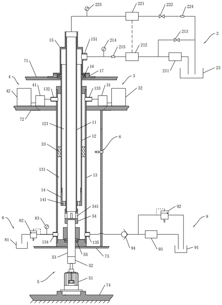
图1为本发明一实施例中双层管双梯度钻井压力调控模拟实验装置的结构示意图;Fig. 1 is a structural schematic diagram of a simulation experiment device for regulating and controlling the drilling pressure with double-layer pipes and double-gradients in an embodiment of the present invention;
图2为本发明一实施例中隔离液位置监测系统的结构原理图;Fig. 2 is a structural principle diagram of the spacer fluid position monitoring system in an embodiment of the present invention;
图3为本发明另一实施例中隔离液位置监测系统的结构原理图。Fig. 3 is a structural principle diagram of a spacer fluid position monitoring system in another embodiment of the present invention.
附图标记说明:Explanation of reference signs:
11-内管,12-外管,121-第一空腔,13-透明管,131-第二空腔,132-第二接头,133-第三接头,134-第四接头,135-第五接头,14-内外管接头,141-通孔,15-内外管端盖,151-第一接头,16-第一轴承,17-第一轴承端盖;11-inner tube, 12-outer tube, 121-first cavity, 13-transparent tube, 131-second cavity, 132-second joint, 133-third joint, 134-fourth joint, 135-the first Five joints, 14-inner and outer pipe joints, 141-through holes, 15-inner and outer pipe end caps, 151-first joints, 16-first bearings, 17-first bearing end caps;
2-钻井液供应控制系统,211-钻井泵,212-涡轮电机,213-第一流量阀,214-第一压力表,215-第一流量计,221-举升泵,222-第二流量阀,223-第二压力表,224-第二流量计,23-浆液池;2-drilling fluid supply control system, 211-drilling pump, 212-turbine motor, 213-first flow valve, 214-first pressure gauge, 215-first flow meter, 221-lift pump, 222-second flow Valve, 223-the second pressure gauge, 224-the second flow meter, 23-the slurry pool;
3-隔离液供应装置,31-第一压力泵,32-第一存储箱,33-隔离液;3-isolating fluid supply device, 31-first pressure pump, 32-first storage tank, 33-isolating fluid;
4-上层流体供应装置,41-第二压力泵,42-第二存储箱;4-upper fluid supply device, 41-second pressure pump, 42-second storage tank;
5-双层管驱动装置,51-驱动电机,52-联轴器,53-传动轴,54-管道接头,541-开孔,55-第二轴承;5-Double pipe driving device, 51-Drive motor, 52-Coupling, 53-Drive shaft, 54-Pipe joint, 541-Open hole, 55-Second bearing;
6-隔离液位置监测系统,61-摄像机,621-第一导轨,622-第一滑块,623-第一电机,624-齿轮,625-齿条;626-第二电机,627-丝杆,628-第二滑块,629-第二导轨;6-Spacing fluid position monitoring system, 61-camera, 621-first guide rail, 622-first slider, 623-first motor, 624-gear, 625-rack; 626-second motor, 627-screw , 628-the second slider, 629-the second guide rail;
71-第一支撑台,72-第二支撑台,73-第三支撑台,74-第四支撑台;71-the first support platform, 72-the second support platform, 73-the third support platform, 74-the fourth support platform;
8-井漏工况模拟系统,81-井漏罐,82-第一溢流阀,83-第三压力表;8- Well leakage condition simulation system, 81- Well leakage tank, 82- The first overflow valve, 83- The third pressure gauge;
9-溢流工况模拟系统,91-溢流罐,92-第二溢流阀,93-溢流泵,94-单向阀。9-overflow condition simulation system, 91-overflow tank, 92-second overflow valve, 93-overflow pump, 94-one-way valve.
本发明目的的实现、功能特点及优点将结合实施例,参照附图做进一步说明。The realization of the purpose of the present invention, functional characteristics and advantages will be further described in conjunction with the embodiments and with reference to the accompanying drawings.
具体实施方式detailed description
下面将结合本发明实施例中的附图,对本发明实施例中的技术方案进行清楚、完整地描述,显然,所描述的实施例仅仅是本发明的一部分实施例,而不是全部的实施例。基于本发明中的实施例,本领域普通技术人员在没有作出创造性劳动前提下所获得的所有其他实施例,都属于本发明保护的范围。The following will clearly and completely describe the technical solutions in the embodiments of the present invention with reference to the accompanying drawings in the embodiments of the present invention. Obviously, the described embodiments are only part of the embodiments of the present invention, not all of them. Based on the embodiments of the present invention, all other embodiments obtained by persons of ordinary skill in the art without creative efforts fall within the protection scope of the present invention.
参照图1,本发明一实施例提供一种双层管双梯度钻井压力调控模拟实验装置,该双层管双梯度钻井压力调控模拟实验装置包括:Referring to Fig. 1, an embodiment of the present invention provides a double-tube dual-gradient drilling pressure control simulation experiment device, the double-tube dual-gradient drilling pressure control simulation test device includes:
井筒主体,井筒主体包括纵向设置的内管11、外管12以及纵向固定设置的透明管13,外管12套设于内管11上,且外管12的内壁与内管11的外壁之间存在间隔并形成第一空腔121;透明管13密封套设于外管12上(具体地,透明管13的上下两端可通过“端盖+环形密封圈”的方式实现密封,其中,透明管13上端处的端盖与外管12之间可通过环形密封圈等方式进行密封),且透明管13的内壁与外管12的外壁之间存在间隔并形成第二空腔131,第二空腔131分别与第一空腔121、内管11的内腔相连通;透明管13的外周表面上设有纵向布置的刻度线或标尺;The wellbore main body, the wellbore main body includes a longitudinally arranged
钻井液供应控制系统2,钻井液供应控制系统2包括钻井液泵送控制装置、泵送压力与流量检测模块、钻井液回流控制装置、回流压力与流量检测模块以及可用于存储钻井液的浆液池23;其中,浆液池23分别与第一空腔121、内管11的内腔相连通,钻井液泵送控制装置和泵送压力与流量检测模块串联连接在浆液池23与第一空腔121之间的通路上,钻井液回流控制装置和回流压力与流量检测模块串联连接在浆液池23与内管11的内腔之间的通路上;Drilling fluid supply control system 2, the drilling fluid supply control system 2 includes a drilling fluid pumping control device, a pumping pressure and flow detection module, a drilling fluid return control device, a return pressure and flow detection module, and a slurry pool that can be used to store
隔离液供应装置33,隔离液供应装置33与第二空腔131相连通,用于向第二空腔131注入隔离液33;The spacer
上层流体供应装置4,上层流体供应装置4与第二空腔131相连通,用于向第二空腔131注入上层流体;其中,上层流体的密度小于隔离液33的密度,隔离液33的密度小于钻井液的密度;The upper layer fluid supply device 4, the upper layer fluid supply device 4 communicates with the
双层管驱动装置5,双层管驱动装置5与内管11的下端或者外管12的下端相连接,用于驱动内管11与外管12共同转动;The double-layer
压力检测单元,压力检测单元设置于透明管13的底部上,用于检测第二空腔131的底部压力(相当于实际钻井现场的井底压力)。A pressure detection unit, the pressure detection unit is arranged on the bottom of the
在本实施例中,需要说明的是,浆液池23与第一空腔121之间以及浆液池23与内管11的内腔之间可通过管道等方式实现连通,上述隔离液33为石油领域通用的材料,其具体组分已为本领域所公知,此处不再赘述。此外,上述上层流体可以是空气、水等流体,只要密度比隔离液33低即可,本实施例对此不作具体的限定。In this embodiment, it should be noted that the communication between the
本实施例的双层管双梯度钻井压力调控模拟实验装置在进行模拟实验时,可通过纯人工操作的方式进行,也可以通过搭配计算机系统来实现半自动化或全自动化控制的方式进行,本实施例对此不作具体的限定,为方便理解和说明,本实施例以纯人工操作的方式进行模拟实验为例阐述该实验装置的使用原理,具体如下:The double-tube dual-gradient drilling pressure control simulation experiment device of this embodiment can be carried out by purely manual operation, or by a computer system to realize semi-automatic or fully automatic control. This implementation This example does not specifically limit this, for the convenience of understanding and illustration, this embodiment uses the purely manual mode to carry out the simulation experiment as an example to illustrate the use principle of the experimental device, as follows:
模拟实验正式开始前,启动井液泵送控制装置,将浆液池23中的钻井液泵送到井筒主体中,当第二空腔131中的钻井液高度达到所需高度(例如处于透明管13的中部位置)时,关闭井液泵送控制装置;接着通过隔离液供应装置33向填充有部分钻井液的第二空腔131中注入定量(具体的量可根据实验需求灵活选定)的隔离液33,注入完成后关闭隔离液供应装置33;紧接着通过上层流体供应装置4向填充有隔离液33的第二空腔131中注入上层流体,直至隔离液33上方充满上层流体后关闭上层流体供应装置4;然后再次启动井液泵送控制装置,直至钻井液充满第一空腔121、第二空腔131和内管11的内腔均充满钻井液时,关闭井液泵送控制装置;此时,可通过透明管13上的刻度线或标尺记录隔离液33的初始位置。Before the formal start of the simulation experiment, start the well fluid pumping control device to pump the drilling fluid in the
前期准备工作完成后,正式开始模拟实验:After the preparatory work is completed, the simulation experiment is officially started:
(1)分别启动井液泵送控制装置、井液回流控制装置和双层管驱动装置5,使得一边向井筒主体内泵入钻井液,一边从井筒主体内抽出钻井液,同时驱动内管11和外管12同时旋转,如此,可以真实地模拟双层管双梯度钻井系统的钻井过程,此时,可记录下隔离液33的当前液位位置、压力检测单元所检测到的井底压力参数、泵送压力与流量检测模块所检测到的泵入到井筒内的钻井液的泵入压力和泵入流量,以及回流压力与流量检测模块所检测到的从井筒内抽出的钻井液的回流压力和回流流量。(1) Start the well fluid pumping control device, the well fluid return control device and the double-layer
(2)保持钻井液的回流压力和回流流量不变,同时对井液泵送控制装置进行调节,以改变钻井液的泵入压力和泵入流量(具体地,可将钻井液的泵入压力和泵入流量调大或调小至所需数值),然后再次记录下隔离液33的当前液位位置、压力检测单元所检测到的井底压力参数、泵送压力与流量检测模块所检测到的泵入到井筒内的钻井液的泵入压力和泵入流量,以及回流压力与流量检测模块所检测到的从井筒内抽出的钻井液的回流压力和回流流量。(2) Keep the return pressure and flow rate of the drilling fluid constant, and at the same time adjust the well fluid pumping control device to change the pumping pressure and flow rate of the drilling fluid (specifically, the pumping pressure of the drilling fluid can be adjusted to and the pumping flow rate are adjusted up or down to the required value), and then record the current liquid level position of the
(3)保持钻井液的泵入压力和泵入流量不变,同时对井液回流控制装置进行调节,以改变钻井液的回流压力和回流流量(具体地,可将钻井液的回流压力和回流流量调大或调小至所需数值),然后再次记录下隔离液33的当前液位位置、压力检测单元所检测到的井底压力参数、泵送压力与流量检测模块所检测到的泵入到井筒内的钻井液的泵入压力和泵入流量,以及回流压力与流量检测模块所检测到的从井筒内抽出的钻井液的回流压力和回流流量。(3) Keep the pumping pressure and flow rate of the drilling fluid constant, and at the same time adjust the well fluid return control device to change the return pressure and return flow rate of the drilling fluid (specifically, the return pressure and return flow rate of the drilling fluid can be adjusted to increase or decrease the flow rate to the required value), and then record the current liquid level position of the
(4)同时对井液泵送控制装置和井液回流控制装置进行调节,以改变(调大或调小)钻井液的泵入压力、泵入流量、回流压力和回流流量,然后再次记录下隔离液33的当前液位位置、压力检测单元所检测到的井底压力参数、泵送压力与流量检测模块所检测到的泵入到井筒内的钻井液的泵入压力和泵入流量,以及回流压力与流量检测模块所检测到的从井筒内抽出的钻井液的回流压力和回流流量。(4) Adjust the well fluid pumping control device and the well fluid return control device at the same time to change (increase or decrease) the pumping pressure, pumping flow rate, return pressure and return flow rate of the drilling fluid, and then record again The current liquid level position of the
由此可见,本实施例提供的双层管双梯度钻井压力调控模拟实验装置,通过设置钻井液供应控制系统2用以向井筒主体循环供应钻井液、设置隔离液供应装置33用以向井筒主体提供实验所需的隔离液33、设置上层液体供应装置用以向井筒主体提供实验所需的上层流体以及设置双层管驱动装置5用以驱动双层管旋转,如此,可以真实地模拟双层管双梯度钻井系统的钻井过程;同时在进行模拟实验的过程中,可以根据实验需求,通过改变钻井液泵送控制装置的泵入压力、泵入流量等钻井液输入参数,和/或改变钻井液回流控制装置的回流压力和回流流量等钻井液输出参数,来实现对隔离液33位置和井底压力的调控,而且在对隔离液33位置和井底压力进行调控的过程中,可通过泵送压力与流量检测模块获取钻井液的泵入压力、泵入流量等输入参数,通过回流压力与流量检测模块获取钻井液的回流压力、回流流量等输出参数,通过位于透明管13底部的压力检测单元获取调控后的井底压力,以及通过透明管13上的刻度线或标尺获取隔离液33的位置变化,从而可测试出不同的钻井液输入/输出参数对井底压力的调控效果的影响,以及钻井液输入/输出参数、井底压力和隔离液33位置变化这三方面之间的对应关系。如此,不仅可为开展双层管双梯度钻井压力调控的物理模拟试验提供设备支撑,而且可为实际的双层管双梯度钻井压力调控现场提供科学的实验数据,提高钻井的安全性。It can be seen that the double-tube dual-gradient drilling pressure control simulation experiment device provided in this embodiment is provided with a drilling fluid supply control system 2 to circulate and supply drilling fluid to the wellbore body, and a spacer
进一步地,参照图1,在一个示例性的实施例中,钻井液泵送控制装置包括钻井泵211、涡轮电机212和第一流量阀213(用以同步调节钻井液的泵入压力和泵入流量),泵送压力与流量检测模块包括第一压力表214(用以测量钻井液的泵入压力)和第一流量计215(用以测量钻井液的泵入流量),钻井液回流控制装置包括举升泵221和第二流量阀222(用以同步调节钻井液的回流压力和回流流量),回流压力与流量检测模块包括第二压力表223(用以测量钻井液的回流压力)和第二流量计224(用以测量钻井液的回流流量);钻井泵211与第一流量阀213相并联,且浆液池23分别通过钻井泵211、第一流量阀213与涡轮电机212的进液口相连通,涡轮电机212的出液口依次经过第一流量计215、第一压力表214后与第一空腔121的顶部相连通,涡轮电机212的输出轴与举升泵221的输入轴相连接;内管11的内腔顶部依次经过第二压力表223、举升泵221、第二流量阀222、第二流量计224后与浆液池23相连通。Further, referring to Fig. 1, in an exemplary embodiment, the drilling fluid pumping control device includes a
在本实施例中,该钻井液供应控制系统2的工作原理如下:In this embodiment, the working principle of the drilling fluid supply control system 2 is as follows:
钻井泵211启动后,钻井泵211将钻井液从浆液池23中泵入到涡轮电机212中,其中,利用第一流量阀213可旁路调节泵入涡轮电机212中的钻井液流量;涡轮电机212在泵入流量的驱动下转动,进而同步驱动举升泵221转动,其中,利用第二流量阀222可调节回流至浆液池23的钻井液流量;如此,使得钻井泵211、涡轮电机212和举升泵221可实现同步运转,最终使得一方面浆液池23中的钻井液可先后经过钻井泵211、涡轮电机212、第一流量计215和第一压力表214后被泵入到第一空腔121中,另一方面内管11内腔中的钻井液可先后经过第二压力表223、举升泵221、第二流量阀222和第二流量计224后被抽回浆液池23中,从而实现钻井液的循环供应。After the
由此可见,本实施例的钻井液供应控制系统2基于上述结构设计,不仅可控制钻井液的循环供应,而且钻井泵211、涡轮电机212和举升泵221可实现同步运转,从而有利于提高了设备操作的便利性以及钻井液循环供应的连续性。It can be seen that the drilling fluid supply control system 2 of this embodiment is based on the above-mentioned structural design, not only can control the circulation supply of drilling fluid, but also the
进一步地,参照图1,在一个示例性的实施例中,隔离液供应装置33包括第一压力泵31和存储有隔离液33的第一存储箱32,第一压力泵31的进液口与第一存储箱32相连通(如通过管道进行连通),第一压力泵31的出液口与第二空腔131的顶部相连通(如通过管道进行连通)。图示性地,透明管13的顶部设有与第二空腔131相连通的第二接头132,如此,可便于通过管道的方式将第一压力泵31的出液口与第二空腔131的顶部进行连通。Further, referring to FIG. 1 , in an exemplary embodiment, the spacer
在本实施例中,基于上述结构设计,使得在进行实验的前期准备工作时,不仅可通过第一压力泵31将存储在第一存储箱32中的隔离液33注入到第二空腔131中,而且在一些使用场景中,即便第二空腔131中充满了钻井液,也可以通过第一压力泵31的压力作用将隔离液33注入到第二空腔131中(此时,位于内管11内腔顶部的部分钻井液会被挤出来),如此在后续往第二空腔131中注入上层流体时可便于调节隔离液33在第二空腔131中的初始位置。此处需要说明的是,在一些具体的应用场景中,还可以在第一压力泵31的出液口与第二空腔131的顶部之间的通路上增设流量计用以实现隔离液33的定量注入;此外,在另一些使用场景中,亦可去掉第一压力泵31而改用开关阀来控制隔离液33的注入(即,在第一压力泵31的出液口与第二空腔131的顶部之间的通路上设置开关阀,打开开关阀后,通过重力作用将第一存储箱32中的隔离液33注入到填充有部分钻井液的第二空腔131中),此处不再赘述。In this embodiment, based on the above-mentioned structural design, when performing the preparatory work for the experiment, not only the
进一步地,参照图1,在一个示例性的实施例中,上层流体供应装置4包括第二压力泵41和存储有上层流体的第二存储箱42,第二压力泵41的入口与第二存储箱42相连通(如通过管道进行连通),第二压力泵41的出口与第二空腔131的顶部相连通(如通过管道进行连通)。图示性地,透明管13的顶部设有与第二空腔131相连通的第三接头133,如此,可便于通过管道的方式将第二压力泵41的出液口与第二空腔131的顶部进行连通。Further, referring to FIG. 1 , in an exemplary embodiment, the upper fluid supply device 4 includes a second pressure pump 41 and a
在本实施例中,基于上述结构设计,使得在进行实验的前期准备工作时,不仅可通过第二压力泵41将存储在第二存储箱42中的上层流体(例如水)注入到第二空腔131中,而且在一些使用场景中,即便第二空腔131中充满了钻井液,也可以通过第二压力泵41的压力作用将上层流体注入到第二空腔131中(此时,位于内管11内腔顶部的部分钻井液会被挤出来),如此可便于调节隔离液33在第二空腔131中的初始位置(例如将隔离液33调节至透明管13的中部位置)。此处需要说明的是,在一些具体的应用场景中,还可以在第二压力泵41的出液口与第二空腔131的顶部之间的通路上增设流量计用以实现上层流体的定量注入;此外,在另一些使用场景中,亦可去掉第二压力泵41而改用开关阀来控制上层流体的注入(即,在第二压力泵41的出液口与第二空腔131的顶部之间的通路上设置开关阀,打开开关阀后,通过重力作用将第二存储箱42中的上层流体注入到填充有部分钻井液和隔离液33的第二空腔131中),此处不再赘述。In this embodiment, based on the above-mentioned structural design, when carrying out the preparatory work of the experiment, not only the upper layer fluid (such as water) stored in the
进一步地,参照图1,在一个示例性的实施例中,双层管驱动装置5包括驱动电机51、联轴器52,以及与内管11同轴设置的传动轴53和管道接头54;驱动电机51的输出轴通过联轴器52与传动轴53的一端相连接,传动轴53的另一端穿过透明管13的下端后与管道接头54的一端相连接(具体地,管道接头54的一端与传动轴53的另一端之间可通过螺纹配合等方式实现连接),管道接头54的另一端与内管11的下端相连接(具体地,管道接头54的另一端与内管11的下端之间可通过螺纹配合等方式实现连接),且管道接头54的内腔与内管11的内腔相连通;管道接头54的外周表面上开设有若干个开孔541,第二空腔131通过若干个开孔541与管道接头54的内腔相连通。Further, referring to FIG. 1 , in an exemplary embodiment, the double-layer
在本实施例中,基于上述结构设计,不仅可通过电机驱动内管11和外管12同时转动,用以模拟实际现场中钻头钻井的过程,而且通过设计专门的管道接头54,不仅可起到部件之间的连接作用,而且可巧妙地将第二空腔131与内管11的内腔进行导通,使得在举升泵221的作用下,第二空腔131中的钻井液可流进内管11的内腔中,以实现钻井液的回流。其中,在具体实施时,为提高传动的稳定性,可在传动轴53上套设第二轴承55,图示性地,第二轴承55安装于透明管13下端处的端盖(图中未标示出)上并通过第二轴承55端盖(图中未标示出)进行遮盖。In this embodiment, based on the above structural design, not only can the motor drive the
进一步地,参照图1,在一个示例性的实施例中,双层管双梯度钻井压力调控模拟实验装置还包括:隔离液位置监测系统6,隔离液位置监测系统6朝向透明管13的外周表面设置,用于当第二空腔131内注入有隔离液33时,监测隔离液33的位置变化。Further, referring to FIG. 1 , in an exemplary embodiment, the double-layer tube dual-gradient drilling pressure regulation simulation experiment device further includes: a spacer fluid
在本实施例中,基于上述结构设计,通过设置隔离液位置监测系统6用以实时监测并记录实验过程中隔离液33的液位变化,可替代人工观察和记录的方式,从而可有效提高实验操作的便利性和时效性。In this embodiment, based on the above-mentioned structural design, by setting the spacer fluid
进一步地,参照图1,在一个示例性的实施例中,隔离液位置监测系统6包括摄像机61和升降机构,摄像机61安装于升降机构上并朝向透明管13的外周表面设置;升降机构用于对摄像机61进行升降,以监测隔离液33的位置变化。Further, referring to FIG. 1 , in an exemplary embodiment, the spacer fluid
在本实施例中,具体地,在进行实验的前期准备工作时,可将摄像机61朝向隔离液33的所在位置设置,在进行模拟实验的过程中,当井底压力升高(或降低)某个压力值时,隔离液33在压力作用下会向上(或向下)移动一定的距离,当摄像机61监测到隔离液33的位置发生移动时,升降机构驱动摄像机61同步上升,从而实现对隔离液33的位置跟踪,此外,在摄像机61对隔离液33的位置进行同步追踪的过程中,摄像机61通过实时对隔离液33的位置进行拍照和/或录像(在一些具体的应用场景中,摄像机61所采集到的图像信息和/或视频信息可上传至计算机系统中进行展示和/或保存),从而可记录实验过程中隔离液33的液位变化,如此,通过一边对隔离液33的位置进行跟踪,一边对隔离液33的位置进行记录,从而实现对隔离液33的位置变化的实时监测,有效提高了实验操作的便利性和时效性。此处需要说明的是,在一些应用场景中,升降机构的控制可通过计算机系统来实现,在另一些应用场景中,也可以通过摄像机61中的控制芯片来实现(具体地,当摄像机61监测到隔离液33的位置发生移动时,摄像机61中的控制芯片会向升降机构发送相应的控制信号,以使升降机构驱动摄像机61上升或下降),本实施例对此不作具体的限制。此处需要说明的是,在本实施例中,摄像机61实现移动追踪功能需要搭配软件来实现,由于摄像机61软件层面的移动跟踪技术已是本领域非常成熟的技术,因此此处不作赘述。In this embodiment, specifically, during the preparatory work of the experiment, the
进一步地,参照图1和图2,在一个示例性的实施例中,升降机构包括齿轮624齿条625升降装置,该齿轮624齿条625升降装置包括纵向设置的第一导轨621、滑动配合于第一导轨621上的第一滑块622、安装于第一滑块622上的第一电机623以及套设于第一电机623的输出轴上的齿轮624,第一导轨621背向第一滑块622的一侧上固定有纵向设置的齿条625,齿条625与齿轮624相啮合,摄像机61安装于第一滑块622上,且摄像机61与第一电机623信号连接(具体地,摄像机61与第一电机623之间可通过有线(如导线等)或无线(如蓝牙等)的方式实现信号连接)。Further, with reference to Fig. 1 and Fig. 2, in an exemplary embodiment, the elevating mechanism comprises a
在本实施例中,具体地,在一些应用场景中,当第一电机623接收到摄像机61发送的控制信号时,第一电机623驱动齿轮624进行转动,使得齿轮624与齿条625之间可发生相互作用,而由于齿条625是固定设置的,因此齿轮624施加于齿条625上的驱动力会反作用于齿轮624上,最终使得第一滑块622可沿着第一导轨621向上或向下滑动,进而使得安装于第一滑块622上的摄像机61可向上或向下移动,从而实现对隔离液33的位置追踪。In this embodiment, specifically, in some application scenarios, when the
进一步地,参照图1和图3,在另一个示例性的实施例中,升降机构包括滚珠丝杆627升降装置,该滚珠丝杆627升降装置包括第二电机626、纵向设置的丝杆627、纵向设置的第二导轨629以及螺纹套设于丝杆627上的第二滑块628,第二滑块628的表面与第二导轨629滑动配合,摄像机61安装于第二滑块628上,且摄像机61与第二电机626信号连接(具体地,摄像机61与第二电机626之间可通过有线(如导线等)或无线(如蓝牙等)的方式实现信号连接)。Further, referring to Fig. 1 and Fig. 3, in another exemplary embodiment, the lifting mechanism includes a
在本实施例中,具体地,在一些应用场景中,当第二电机626接收到摄像机61发送的控制信号时,第二电机626驱动丝杆627进行旋转,由于第二滑块628是通过螺纹配合的方式套设于丝杆627上的,因此在丝杆627进行旋转的过程中,丝杆627可驱动第二滑块628沿着第二导轨629向上或向下滑动,进而使得安装于第二滑块628上的摄像机61可向上或向下移动,从而实现对隔离液33的位置追踪。In this embodiment, specifically, in some application scenarios, when the
进一步地,参照图1,在一个示例性的实施例中,井筒主体还包括与内管11同轴设置的内外管接头14,内外管接头14的上端与外管12的下端相配合(具体地,内外管接头14的上端与外管12的下端螺纹配合),内外管接头14的下端套设于内管11上(具体地,内外管接头14的下端通过螺纹配合的方式套设于内管11上),且内外管接头14的内腔与第一空腔121相连通,内外管接头14的表面上开设有若干个通孔141,第二空腔131通过若干个通孔141与内外管接头14的内腔相连通。Further, referring to FIG. 1 , in an exemplary embodiment, the wellbore body further includes an inner and outer pipe joint 14 coaxially arranged with the
在本实施例中,基于上述结构设计,通过设置设计专门的内外管接头14,不仅可便于内管11与外管12之间的连接,而且可便于第一空腔121与第二空腔131之间的连通。In this embodiment, based on the above structural design, by setting a specially designed inner and outer pipe joint 14, not only the connection between the
进一步地,参照图1,在一个示例性的实施例中,井筒主体还包括与内管11同轴设置的内外管端盖15,内外管端盖15具有同轴设置的第一管道部和第二管道部,第一管道部套设于内管11的上端且第一管道部的内腔与内管11的内腔相连通,第二管道部套设于外管12的上端且第二管道部的内腔与第一空腔121相连通,第二管道部的外周表面上设置有第一接头151,第一接头151的一端与第二管道部的内腔相连通,第一接头151的另一端与浆液池23相连通(具体地,第一接头151的另一端与浆液池23之间可通过管道等方式进行连通),第一管道部的内腔与浆液池23相连通。Further, referring to FIG. 1 , in an exemplary embodiment, the wellbore body further includes an inner and outer
在本实施例中,基于上述结构设计,通过设置设计专门的内外管端盖15,可便于同时将浆液池23与第一空腔121、内管11的内腔进行连通。In this embodiment, based on the above-mentioned structural design, the
进一步地,参照图1,在一个示例性的实施例中,双层管双梯度钻井压力调控模拟实验装置还包括支架,支架具有由上至下依次间隔设置的第一支撑台71、第二支撑台72、第三支撑台73和第四支撑台74,双层管驱动装置5至少部分安装于第四支撑台74上(具体地,驱动电机51安装于第四支撑台74上),透明管13的下端放置于第三支撑台73上,透明管13的上端穿过第二支撑台72并与第二支撑台72相固定,外管12的上端穿过第一支撑台71并与第一支撑台71转动配合(具体地,外管12的顶部设置有环形轴肩(图中未标示出)以及套设有第一轴承16,第一支撑台71上设置有可容纳第一轴承16的凹槽,其中,第一轴承16位于凹槽与环形轴肩之间,内外管端盖15与环形轴肩之间安装有用于对环形轴肩和第一轴承16进行遮盖的第一轴承端盖17),隔离液供应装置33、上层流体供应装置4均位于第二支撑台72上,隔离液位置监测系统6位于第二支撑台72与第三支撑台73之间。Further, referring to FIG. 1 , in an exemplary embodiment, the double-layer pipe double-gradient drilling pressure control simulation experiment device also includes a bracket, and the bracket has a first support platform 71 and a second support platform arranged at intervals from top to bottom.
在本实施例中,基于上述结构设计,通过设置具有多个支撑台的支架,可为相关零部件的安装提供支撑载体,有利于提高零部件组装的便利性。In this embodiment, based on the above structural design, by providing a bracket with a plurality of support platforms, a support carrier can be provided for the installation of related components, which is beneficial to improve the convenience of component assembly.
进一步地,参照图1,在一个示例性的实施例中,双层管双梯度钻井压力调控模拟实验装置还包括:井漏工况模拟系统8,井漏工况模拟系统8包括第三压力表83、第一溢流阀82以及可用于收容钻井液的井漏罐81,第二空腔131的底部依次经过第三压力表83、第一溢流阀82后与井漏罐81相连通。其中,在具体实施时,第三压力表83可作为上述压力检测单元,用以检测第二空腔131的底部压力;透明管13的底部上设置有第四接头134,以便于通过管道的方式将第二空腔131的底部与井漏罐81之间进行连通。Further, referring to FIG. 1 , in an exemplary embodiment, the double-tube dual-gradient drilling pressure control simulation experiment device further includes: a lost circulation condition simulation system 8, and the lost circulation condition simulation system 8 includes a
在本实施例中,具体地,当井底压力超出第一溢流阀82的预定压力阀值,第一溢流阀82打开,透明管13底部的钻井液流出至井漏罐81中,从而可模拟井漏工况对隔离液33波动及井底压力的影响,进而通过调节钻井液的输入/输出参数,并记录调节后的井底压力值和隔离液33的位置变化,如此,可研究出在井漏工况下钻井液的输入/输出参数对井底压力和隔离液33位置的调控能力,即,通过实验可获取消除井漏现象的相关调节参数(相关调节参数包括钻井液的泵入压力、泵入流量、回流压力和回流流量),从而可为实际的现场作业提供科学的数据指导,以便现场发生井漏现象时,可及时对井底压力进行调控,避免安全事故的发生。In this embodiment, specifically, when the bottomhole pressure exceeds the predetermined pressure threshold of the first relief valve 82, the first relief valve 82 is opened, and the drilling fluid at the bottom of the
进一步地,参照图1,在一个示例性的实施例中,双层管双梯度钻井压力调控模拟实验装置还包括:溢流工况模拟系统9,溢流工况模拟系统9包括单向阀94、第二溢流阀92、溢流泵93以及可用于存储钻井液的溢流罐91,第二溢流阀92与溢流泵93相并联,且溢流罐91分别通过第二溢流阀92、溢流泵93与单向阀94的进液口相连通,单向阀94的出液口与第二空腔131的底部相连通。透明管13的底部上还设置有第五接头135,以便于通过管道的方式将第二空腔131的底部与溢流罐91之间进行连通。Further, referring to FIG. 1 , in an exemplary embodiment, the double-tube dual-gradient drilling pressure control simulation experiment device further includes: an overflow condition simulation system 9, and the overflow condition simulation system 9 includes a one-
在本实施例中,具体地,当井底压力低于第二溢流阀92的预定压力阀值,第二溢流阀92关闭,单向阀94打开,溢流泵93将溢流罐91中的钻井液泵入第二空腔131中,从而可模拟溢流工况对隔离液33波动及井底压力的影响,进而通过调节钻井液的输入/输出参数,并记录调节后的井底压力值和隔离液33的位置变化,如此,可研究出在溢流工况下钻井液的输入/输出参数对井底压力和隔离液33位置的调控能力,即,通过实验可获取消除溢流现象的相关调节参数(相关调节参数包括钻井液的泵入压力、泵入流量、回流压力和回流流量),从而可为实际的现场作业提供科学的数据指导,以便现场发生溢流现象时,可及时对井底压力进行调控,避免安全事故的发生。In this embodiment, specifically, when the bottom hole pressure is lower than the predetermined pressure threshold value of the
对应地,本发明实施例还提供一种应用于上述任一实施例中的双层管双梯度钻井压力调控模拟实验装置的测试方法,该测试方法可应用于计算机系统中,计算机系统通过有线(如导线等)或无线(如蓝牙、WiFi等)的方式与相关电子元器件信号连接,具体地,该测试方法包括以下步骤:Correspondingly, the embodiment of the present invention also provides a test method applied to the simulation experiment device for regulating and controlling the double-tube dual-gradient drilling pressure in any of the above-mentioned embodiments. Such as wires, etc.) or wireless (such as Bluetooth, WiFi, etc.) and related electronic components, specifically, the test method includes the following steps:
步骤S1,通过钻井液泵送控制装置将浆液池23中的钻井液泵送至第一空腔121中,直至第一空腔121、第二空腔131和内管11的内腔均充满钻井液时,关闭钻井液泵送控制装置;Step S1, pump the drilling fluid in the
步骤S2,通过隔离液供应装置33向填充有钻井液的第二空腔131中注入定量的隔离液33,注入完成后,关闭隔离液供应装置33;Step S2, inject a certain amount of
步骤S3,通过上层流体供应装置4向填充有钻井液和隔离液33的第二空腔131中注入定量的上层流体,直至将隔离液33的位置调节到指定位置时,关闭上层流体供应装置4,其中,隔离液位置监测系统6朝向隔离液33设置;Step S3, inject a certain amount of upper layer fluid into the
步骤S4,分别开启钻井液泵送控制装置、钻井液回流控制装置和双层管驱动装置5;Step S4, respectively turning on the drilling fluid pumping control device, the drilling fluid return control device and the double-layer
步骤S5,调节钻井液泵送控制装置和/或钻井液回流控制装置,以改变泵送至井筒主体内的钻井液的泵送流量和/或回流至浆液池23的钻井液的回流流量;Step S5, adjusting the drilling fluid pumping control device and/or the drilling fluid return control device to change the pumping flow rate of the drilling fluid pumped into the wellbore body and/or the return flow rate of the drilling fluid returned to the
步骤S6,在泵送流量和/或回流流量发生改变的状况下,通过隔离液位置监测系统6监测并记录隔离液33的位置偏移量、通过泵送压力与流量检测模块记录钻井液的泵送压力和泵送流量,以及通过回流压力与流量检测模块记录钻井液的回流压力和回流流量。Step S6, when the pumping flow rate and/or return flow rate change, monitor and record the position offset of the
在上述步骤S1中,具体地,控制钻井泵211开启,直至第二空腔131、第一空腔121和内管11的内腔先后充满钻井液后,控制钻井泵211关闭。In the above step S1, specifically, the
在上述步骤S2中,具体地,控制第一压力泵31开启,直至将第一存储箱32中的隔离液33泵入第二空腔131后(隔离液33泵入的量可根据需要而定,具体可通过设置流量计来控制隔离液33的泵入量),控制第一压力泵31关闭,此时,隔离液33位于第二空腔131的顶部上。In the above step S2, specifically, the
在上述步骤S3中,具体地,控制第二压力泵41开启,将第二存储箱42中的上层流体泵入第二空腔131中,并通过控制上层流体的泵入量(上层流体的泵入量可根据需要而定,具体可通过设置流量计来控制上层流体的泵入量)来调节隔离液33的位置,直至隔离液33的位置到达所需位置时(例如透明管13的中部位置),控制第二压力泵41关闭,此时摄像机61朝向隔离液33的所在位置设置。In the above step S3, specifically, the second pressure pump 41 is controlled to be turned on, and the upper layer fluid in the
在上述步骤S4中,具体地,分别控制钻井泵211、驱动电机51开启,开始进行模拟实验;此时钻井泵211、涡轮电机212、举升泵221和驱动电机51均处于运转状态,从而可以真实地模拟双层管双梯度钻井系统的钻井过程。In the above-mentioned step S4, specifically, the
在上述步骤S5中,具体地,通过调节第一流量阀213,可改变泵送至井筒主体内的钻井液的泵送流量和泵送压力;通过调节第二流量阀222,可改变回流至浆液池23的钻井液的回流流量和回流压力。In the above step S5, specifically, by adjusting the
在上述步骤S6中,具体调控情况包括以下三个方面:In the above step S6, the specific control situation includes the following three aspects:
(1)保持钻井液的回流压力和回流流量不变,同时改变钻井液的泵入压力和泵入流量(具体地,可将钻井液的泵入压力和泵入流量调大或调小至所需数值),然后计算机系统获取在此状态下,摄像机61所记录下的隔离液33的位置变化信息、第三压力表83的压力数值变化、第一压力的压力数值变化、第一流量计215的流量数值变化、第二压力的压力数值变化、第二流量计224的流量数值变化。(1) Keep the return pressure and flow rate of the drilling fluid unchanged, and change the pumping pressure and flow rate of the drilling fluid at the same time (specifically, the pumping pressure and flow rate of the drilling fluid can be adjusted up or down to the desired value; value), and then the computer system acquires the position change information of the
(2)保持钻井液的泵入压力和泵入流量不变,同时改变钻井液的回流压力和回流流量(具体地,可将钻井液的回流压力和回流流量调大或调小至所需数值),然后计算机系统获取在此状态下,摄像机61所记录下的隔离液33的位置变化信息、第三压力表83的压力数值变化、第一压力的压力数值变化、第一流量计215的流量数值变化、第二压力的压力数值变化、第二流量计224的流量数值变化。(2) Keep the pumping pressure and flow rate of the drilling fluid constant, and change the return pressure and flow rate of the drilling fluid at the same time (specifically, the return pressure and flow rate of the drilling fluid can be adjusted up or down to the required value ), and then the computer system acquires in this state, the position change information of the
(3)同时改变钻井液的泵入压力、泵入流量、回流压力和回流流量,然后计算机系统获取在此状态下,摄像机61所记录下的隔离液33的位置变化信息、第三压力表83的压力数值变化、第一压力的压力数值变化、第一流量计215的流量数值变化、第二压力的压力数值变化、第二流量计224的流量数值变化。(3) Change the pumping pressure, pumping flow rate, return pressure and return flow rate of the drilling fluid at the same time, and then the computer system obtains the position change information of the
在本实施例中,基于上述步骤,不仅可实现与上述双层管双梯度钻井压力调控模拟实验装置相同的技术效果,而且提高了实验装置的智能化,使得实验人员更加方便快捷地进行模拟实验,与纯人工操作的方式相比,可大大提高实验的效率。In this embodiment, based on the above steps, not only can achieve the same technical effect as the above-mentioned double-tube dual-gradient drilling pressure control simulation experimental device, but also improve the intelligence of the experimental device, so that the experimenters can conduct simulation experiments more conveniently and quickly , compared with purely manual operation, the efficiency of the experiment can be greatly improved.
需要说明的是,本发明公开的双层管双梯度钻井压力调控模拟实验装置及测试方法的其它内容可参见现有技术,在此不再赘述。It should be noted that other contents of the double-tube dual-gradient drilling pressure control simulation experiment device and test method disclosed in the present invention can be referred to the prior art, and will not be repeated here.
另外,需要说明的是,若本发明实施例中有涉及方向性指示(诸如上、下、左、右、前、后……),则该方向性指示仅用于解释在某一特定姿态(如附图所示)下各部件之间的相对位置关系、运动情况等,如果该特定姿态发生改变时,则该方向性指示也相应地随之改变。In addition, it should be noted that if there are directional indications (such as up, down, left, right, front, back...) in the embodiment of the present invention, the directional indications are only used to explain the direction in a certain posture ( As shown in the accompanying drawings), if the specific posture changes, the directional indication will also change accordingly.
另外,还需要说明的是,在本发明中涉及“第一”、“第二”等的描述仅用于描述目的,而不能理解为指示或暗示其相对重要性或者隐含指明所指示的技术特征的数量。由此,限定有“第一”、“第二”的特征可以明示或者隐含地包括至少一个该特征。另外,各个实施例之间的技术方案可以相互结合,但是必须是以本领域普通技术人员能够实现为基础,当技术方案的结合出现相互矛盾或无法实现时应当认为这种技术方案的结合不存在,也不在本发明要求的保护范围之内。In addition, it should also be noted that the descriptions involving "first", "second" and so on in the present invention are only for descriptive purposes, and cannot be understood as indicating or implying their relative importance or implicitly indicating the indicated technology number of features. Thus, the features defined as "first" and "second" may explicitly or implicitly include at least one of these features. In addition, the technical solutions of the various embodiments can be combined with each other, but it must be based on the realization of those skilled in the art. When the combination of technical solutions is contradictory or cannot be realized, it should be considered that the combination of technical solutions does not exist , nor within the scope of protection required by the present invention.
以上所述仅为本发明的可选实施例,并非因此限制本发明的专利范围,凡是在本发明的构思下,利用本发明说明书及附图内容所作的等效结构变换,或直接/间接运用在其他相关的技术领域均包括在本发明的专利保护范围内。The above descriptions are only optional embodiments of the present invention, and do not limit the patent scope of the present invention. Under the conception of the present invention, the equivalent structural transformation made by using the description of the present invention and the contents of the accompanying drawings, or direct/indirect use All other relevant technical fields are included in the patent protection scope of the present invention.
Claims (9)
Priority Applications (1)
| Application Number | Priority Date | Filing Date | Title |
|---|---|---|---|
| CN202110489030.3A CN113236159B (en) | 2021-04-30 | 2021-04-30 | Double-pipe double-gradient drilling pressure regulation and control simulation experiment device and test method |
Applications Claiming Priority (1)
| Application Number | Priority Date | Filing Date | Title |
|---|---|---|---|
| CN202110489030.3A CN113236159B (en) | 2021-04-30 | 2021-04-30 | Double-pipe double-gradient drilling pressure regulation and control simulation experiment device and test method |
Publications (2)
| Publication Number | Publication Date |
|---|---|
| CN113236159A CN113236159A (en) | 2021-08-10 |
| CN113236159B true CN113236159B (en) | 2022-12-06 |
Family
ID=77131937
Family Applications (1)
| Application Number | Title | Priority Date | Filing Date |
|---|---|---|---|
| CN202110489030.3A Active CN113236159B (en) | 2021-04-30 | 2021-04-30 | Double-pipe double-gradient drilling pressure regulation and control simulation experiment device and test method |
Country Status (1)
| Country | Link |
|---|---|
| CN (1) | CN113236159B (en) |
Families Citing this family (1)
| Publication number | Priority date | Publication date | Assignee | Title |
|---|---|---|---|---|
| CN117868717B (en) * | 2024-03-12 | 2024-05-17 | 宝迈圣本测控技术(天津)有限公司 | A hollow oil and gas well monitoring wellbore for high temperature electric pump oil production |
Family Cites Families (5)
| Publication number | Priority date | Publication date | Assignee | Title |
|---|---|---|---|---|
| US9328575B2 (en) * | 2012-01-31 | 2016-05-03 | Weatherford Technology Holdings, Llc | Dual gradient managed pressure drilling |
| CN205211283U (en) * | 2015-11-17 | 2016-05-04 | 西南石油大学 | Experimental device for two gradient well drillings of efflux under simulation well |
| CN205330658U (en) * | 2016-01-05 | 2016-06-22 | 西南石油大学 | Visual experimental apparatus of simulation gas drilling detritus migration |
| CN108457642A (en) * | 2018-01-25 | 2018-08-28 | 中国石油大学(北京) | A kind of more gradient pressure test devices of pit shaft |
| CN111622697B (en) * | 2020-06-01 | 2021-12-07 | 西南石油大学 | Deep-sea double-layer pipe well bottom three-channel pressure control system and control method |
-
2021
- 2021-04-30 CN CN202110489030.3A patent/CN113236159B/en active Active
Also Published As
| Publication number | Publication date |
|---|---|
| CN113236159A (en) | 2021-08-10 |
Similar Documents
| Publication | Publication Date | Title |
|---|---|---|
| CN104234708B (en) | A kind of multi-functional pit shaft oil gas water multiphase analogue experiment installation | |
| CN103531076B (en) | A set of drilling condition simulation system and workflow thereof | |
| CN109209337B (en) | Horizontal well drilling lubricity experiment device and method considering rock debris bed | |
| CN111827910B (en) | An experimental device and experimental method for exploring the formation of cuttings bed in horizontal well drilling | |
| CN104847287B (en) | A kind of balanced pressure drilling pressure control method | |
| CN114526025A (en) | Remote intelligent active drilling pressure control system and method | |
| CN102852498B (en) | Thick oil well bore lifting viscosity reduction analogue means and method | |
| CN204113282U (en) | A kind of multi-functional pit shaft oil gas water multiphase analogue experiment installation | |
| CN105041280A (en) | Method and device for realizing carbon dioxide miscible-phase displacement laboratory experiment | |
| CN104373105A (en) | Shaft-simulating multifunctional flowing test system | |
| CN104821129A (en) | Drilling well control simulation teaching experimental device | |
| CN203756087U (en) | Pressure-balanced drilling pressure controller | |
| CN104948149B (en) | A kind of multimedium dispensing system suitable in mining site complexity oil reservoir | |
| CN102418509B (en) | Indoor test system and method for managed pressure drilling technology | |
| CN110388231A (en) | Cavity construction device and method for salt cavern gas storage | |
| CN105952438A (en) | Visualized two-dimensional physical simulation experiment device for thermal thickened-oil extraction | |
| CN113236159B (en) | Double-pipe double-gradient drilling pressure regulation and control simulation experiment device and test method | |
| CN115219321A (en) | Experimental device and method for testing wellbore pressure under jetting and leakage coexisting working conditions | |
| CN113062733B (en) | Segmented horizontal well water control three-dimensional simulation experiment device and experiment method thereof | |
| CN110306976A (en) | Inert gas injection control annular pressure test device and its test method | |
| CN104018824A (en) | Zonation testing method used for downhole intelligent well shutdown | |
| CN205786538U (en) | Hypertonic stress drill in fluid protective capability field evaluation device | |
| CN212750165U (en) | Device for simulating phase state switching of oil-in-water/oil-in-water drilling fluid in shaft | |
| CN106596346A (en) | Device and method for controlling displacement amount in reservoir rock wettability determination | |
| CN114034565B (en) | Online evaluation device and evaluation method for sand fixation effect of chemical sand fixation agent |
Legal Events
| Date | Code | Title | Description |
|---|---|---|---|
| PB01 | Publication | ||
| PB01 | Publication | ||
| SE01 | Entry into force of request for substantive examination | ||
| SE01 | Entry into force of request for substantive examination | ||
| GR01 | Patent grant | ||
| GR01 | Patent grant |