CN113202186B - Steel construction antidetonation frame construction and steel construction assembled earthquake-resistant building - Google Patents
Steel construction antidetonation frame construction and steel construction assembled earthquake-resistant building Download PDFInfo
- Publication number
- CN113202186B CN113202186B CN202110489508.2A CN202110489508A CN113202186B CN 113202186 B CN113202186 B CN 113202186B CN 202110489508 A CN202110489508 A CN 202110489508A CN 113202186 B CN113202186 B CN 113202186B
- Authority
- CN
- China
- Prior art keywords
- steel
- support plate
- plate
- supporting
- blocks
- Prior art date
- Legal status (The legal status is an assumption and is not a legal conclusion. Google has not performed a legal analysis and makes no representation as to the accuracy of the status listed.)
- Active
Links
Images


Classifications
-
- E—FIXED CONSTRUCTIONS
- E04—BUILDING
- E04B—GENERAL BUILDING CONSTRUCTIONS; WALLS, e.g. PARTITIONS; ROOFS; FLOORS; CEILINGS; INSULATION OR OTHER PROTECTION OF BUILDINGS
- E04B1/00—Constructions in general; Structures which are not restricted either to walls, e.g. partitions, or floors or ceilings or roofs
- E04B1/18—Structures comprising elongated load-supporting parts, e.g. columns, girders, skeletons
- E04B1/24—Structures comprising elongated load-supporting parts, e.g. columns, girders, skeletons the supporting parts consisting of metal
- E04B1/2403—Connection details of the elongated load-supporting parts
-
- E—FIXED CONSTRUCTIONS
- E04—BUILDING
- E04B—GENERAL BUILDING CONSTRUCTIONS; WALLS, e.g. PARTITIONS; ROOFS; FLOORS; CEILINGS; INSULATION OR OTHER PROTECTION OF BUILDINGS
- E04B1/00—Constructions in general; Structures which are not restricted either to walls, e.g. partitions, or floors or ceilings or roofs
- E04B1/62—Insulation or other protection; Elements or use of specified material therefor
- E04B1/92—Protection against other undesired influences or dangers
- E04B1/98—Protection against other undesired influences or dangers against vibrations or shocks; against mechanical destruction, e.g. by air-raids
-
- E—FIXED CONSTRUCTIONS
- E04—BUILDING
- E04C—STRUCTURAL ELEMENTS; BUILDING MATERIALS
- E04C3/00—Structural elongated elements designed for load-supporting
- E04C3/02—Joists; Girders, trusses, or trusslike structures, e.g. prefabricated; Lintels; Transoms; Braces
- E04C3/04—Joists; Girders, trusses, or trusslike structures, e.g. prefabricated; Lintels; Transoms; Braces of metal
-
- E—FIXED CONSTRUCTIONS
- E04—BUILDING
- E04H—BUILDINGS OR LIKE STRUCTURES FOR PARTICULAR PURPOSES; SWIMMING OR SPLASH BATHS OR POOLS; MASTS; FENCING; TENTS OR CANOPIES, IN GENERAL
- E04H9/00—Buildings, groups of buildings or shelters adapted to withstand or provide protection against abnormal external influences, e.g. war-like action, earthquake or extreme climate
- E04H9/02—Buildings, groups of buildings or shelters adapted to withstand or provide protection against abnormal external influences, e.g. war-like action, earthquake or extreme climate withstanding earthquake or sinking of ground
- E04H9/021—Bearing, supporting or connecting constructions specially adapted for such buildings
-
- E—FIXED CONSTRUCTIONS
- E04—BUILDING
- E04H—BUILDINGS OR LIKE STRUCTURES FOR PARTICULAR PURPOSES; SWIMMING OR SPLASH BATHS OR POOLS; MASTS; FENCING; TENTS OR CANOPIES, IN GENERAL
- E04H9/00—Buildings, groups of buildings or shelters adapted to withstand or provide protection against abnormal external influences, e.g. war-like action, earthquake or extreme climate
- E04H9/02—Buildings, groups of buildings or shelters adapted to withstand or provide protection against abnormal external influences, e.g. war-like action, earthquake or extreme climate withstanding earthquake or sinking of ground
- E04H9/024—Structures with steel columns and beams
-
- E—FIXED CONSTRUCTIONS
- E04—BUILDING
- E04B—GENERAL BUILDING CONSTRUCTIONS; WALLS, e.g. PARTITIONS; ROOFS; FLOORS; CEILINGS; INSULATION OR OTHER PROTECTION OF BUILDINGS
- E04B1/00—Constructions in general; Structures which are not restricted either to walls, e.g. partitions, or floors or ceilings or roofs
- E04B1/18—Structures comprising elongated load-supporting parts, e.g. columns, girders, skeletons
- E04B1/24—Structures comprising elongated load-supporting parts, e.g. columns, girders, skeletons the supporting parts consisting of metal
- E04B1/2403—Connection details of the elongated load-supporting parts
- E04B2001/2406—Connection nodes
Landscapes
- Engineering & Computer Science (AREA)
- Architecture (AREA)
- Civil Engineering (AREA)
- Structural Engineering (AREA)
- Environmental & Geological Engineering (AREA)
- Business, Economics & Management (AREA)
- Emergency Management (AREA)
- Physics & Mathematics (AREA)
- Electromagnetism (AREA)
- Buildings Adapted To Withstand Abnormal External Influences (AREA)
Abstract
The invention discloses a steel structure anti-seismic frame structure and a steel structure fabricated anti-seismic building, which comprise a plurality of groups of support columns vertically arranged on a horizontal substrate, wherein the adjacent support columns are connected through steel beams to form a frame structure; the steel beam comprises an upper support plate and a lower support plate which are parallel to each other, and the upper support plate and the lower support plate are vertically connected through a connecting plate in the middle to form an I-shaped structure; a plurality of groups of positioning grooves for accommodating the supporting blocks are formed in the horizontal planes corresponding to the upper supporting plate and the lower supporting plate at equal intervals; the positions of the steel beams far away from the two ends are provided with damping steel beams capable of moving upwards; the two ends of the steel beam are movably sleeved with adjusting blocks through the arranged sliding grooves, and the other ends of the adjusting blocks are connected with connecting blocks. According to the invention, the scissor type truss structure formed by the connecting rods and the supporting blocks is arranged on the two sides of the I-shaped steel beam, so that when the truss structure is in a compression state, good support can be provided to the radial direction through the supporting blocks.
Description
Technical Field
The invention relates to the technical field of anti-seismic steel structure equipment, in particular to a steel structure anti-seismic frame structure and a steel structure assembled anti-seismic building.
Background
The steel structure assembly type building is a residential structure which is assembled on site together with a cast-in-place floor slab by taking a steel member prefabricated in a factory as a basic structural member, and attaching an inner wall slab and an outer hanging wall slab. The steel structure prefabricated house has the obvious advantages of high strength, light weight, short construction period, good anti-seismic performance, high industrialization degree and the like, and the prefabricated building adopting the prefabricated steel structure is superior to the existing reinforced concrete house in terms of function, cost performance, comfort and safety. The steel structure assembly type building is an ideal development trend of the assembly type building in the future. Chinese patent publication No.: CN107842242A discloses a steel structure anti-seismic frame structure, which can effectively strengthen radial load and buffer axial load by arranging a wave structure formed by bending elastic steel bars on a box girder, and has a certain anti-seismic effect, but the wave structure formed by bending the elastic steel bars is already in a compression stress state when being installed so as to generate the supporting and anti-seismic effects, and the elasticity of the wave structure is greatly reduced after long-term use, so that the supporting and anti-seismic effects are greatly weakened; what is more, the wave-shaped structure formed by bending the elastic steel bars has poor radial support and axial shock absorption, and the anti-seismic effect is not obvious.
Disclosure of Invention
The invention aims to provide a steel structure anti-seismic frame structure and a steel structure assembled anti-seismic building, and aims to solve the problems in the background art.
In order to achieve the purpose, the invention provides the following technical scheme:
a steel structure anti-seismic frame structure comprises a plurality of groups of support columns vertically arranged on a horizontal base plate, wherein adjacent support columns are connected through steel beams to form a frame structure;
the steel beam comprises an upper support plate and a lower support plate which are parallel to each other, and the upper support plate and the lower support plate are vertically connected through a connecting plate in the middle to form an I-shaped structure;
a plurality of groups of positioning grooves for containing supporting blocks are equidistantly formed in the horizontal planes corresponding to the upper supporting plate and the lower supporting plate, connecting lugs are arranged on the supporting blocks, the connecting lugs at the upper and lower adjacent positions of the upper supporting plate and the lower supporting plate are connected through connecting rods, and springs which are in the original length under the normal state are connected between the supporting blocks at the upper and lower opposite positions of the upper supporting plate and the lower supporting plate;
the damping steel beam comprises a T-shaped structure formed by a horizontal support plate and a vertical support plate, the horizontal support plate and the vertical support plate respectively correspond to the upper support plate and the connecting plate, a plurality of groups of connecting shafts are arranged at the lower part of the vertical support plate at equal intervals, and a plurality of groups of connecting holes corresponding to the connecting shafts are formed in the connecting plate;
the adjustable steel beam is characterized in that adjusting blocks are movably sleeved at two ends of the steel beam through the arranged sliding grooves, the other ends of the adjusting blocks are connected with the connecting blocks, adjusting screw rods used for adjusting the positions of the connecting blocks at two ends of the steel beam are arranged between the adjusting blocks and the connecting blocks, and connecting support columns can be detached at the other ends of the connecting blocks.
Preferably, a plurality of groups of connecting holes are formed in the adjusting block, and a plurality of groups of connecting columns corresponding to the connecting holes are arranged on the connecting blocks.
Preferably, an upper clamping block is arranged at the other end of the connecting block, and a lower clamping block corresponding to the upper clamping block is arranged on the supporting column.
Preferably, the link is an elastic member.
Preferably, the sliding groove is formed in the upper support plate and the lower support plate and located on two sides of the connecting plate.
Preferably, the other end of the adjusting block is connected with a connecting lug located on the outermost side of the steel beam.
The application still provides a steel construction assembled earthquake-resistant building, including the aforesaid a steel construction earthquake-resistant frame construction.
Compared with the prior art, the invention has the beneficial effects that:
according to the invention, the scissor type truss structure consisting of the connecting rods and the supporting blocks is arranged on the two sides of the I-shaped steel beam, so that when the truss structure is in a compressed state, good support can be provided to the radial direction through the supporting blocks; more importantly, when the whole steel beam is subjected to transverse inward load, the truss structure can drive the damping steel beam to move upwards, the transverse inward load is buffered through the gravity of the damping steel beam, and the transverse inward load is further buffered through the extension spring after the damping steel beam exceeds the movement distance; when a transverse outward load is applied, the length of the truss structure is extended, the upper and lower corresponding supporting blocks are close to each other, and then the spring is compressed, so that the transverse outward load is buffered, and the transverse outward load has good radial supporting and transverse buffering anti-seismic functions; meanwhile, the spring is not subjected to external force in a normal state and is in an original long state, so that the elasticity of the spring is slowly weakened, and a long-term effective buffering effect can be guaranteed.
Drawings
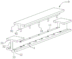
FIG. 1 is a schematic structural view of the present invention;
FIG. 2 is an enlarged schematic view of region A in FIG. 1;
FIG. 3 is a schematic view of the structure of the steel beam and the shock-absorbing steel beam of the present invention;
FIG. 4 is a schematic view of the adjusting block structure of the present invention;
fig. 5 is a schematic view of the connecting block structure of the invention.
In the figure: the damping device comprises a base plate 1, a supporting column 2, a steel beam 3, an upper supporting plate 31, a connecting plate 32, a lower supporting plate 33, a positioning groove 4, a supporting block 5, a connecting lug 6, a connecting rod 7, a spring 8, a damping steel beam 9, a horizontal supporting plate 91, a vertical supporting plate 92, a connecting shaft 10, a connecting hole 11, a sliding groove 12, an adjusting block 13, a connecting hole 14, a connecting block 15, a connecting column 151, an upper clamping block 152, a lower clamping block 16 and an adjusting screw 17.
Detailed Description
The technical solutions in the embodiments of the present invention will be clearly and completely described below with reference to the drawings in the embodiments of the present invention, and it is obvious that the described embodiments are only a part of the embodiments of the present invention, and not all of the embodiments. All other embodiments, which can be derived by a person skilled in the art from the embodiments given herein without making any creative effort, shall fall within the protection scope of the present invention.
Referring to fig. 1-5, the present invention provides a technical solution:
a steel structure anti-seismic frame structure comprises a plurality of groups of supporting columns 2 vertically arranged on a horizontal base plate 1, wherein the horizontal base plate 1 is of a concrete structure and forms the lower part of the whole device to be stably connected, and the arrangement number and the arrangement positions of the supporting columns 2 can be set according to actual spatial arrangement and overall stress configuration; the adjacent supporting columns 2 are connected through the steel beams 3 to form a frame structure, and the frame structure can enhance the structural strength of the whole device and avoid the defect of overlarge weight caused by integral pouring;
the steel beam 3 comprises an upper support plate 31 and a lower support plate 33 which are parallel to each other, and the upper support plate 31 and the lower support plate 33 are vertically connected through a connecting plate 32 at the middle part to form an I-shaped structure;
a plurality of groups of positioning grooves 4 for containing the supporting blocks 5 are equidistantly formed in the horizontal planes corresponding to the upper supporting plate 31 and the lower supporting plate 33, the supporting blocks 5 are arranged in the positioning grooves 4, the positioning grooves 4 can limit the supporting blocks 5, so that the positions of the supporting blocks 5 cannot change when the steel beam 3 is subjected to corresponding loads, the stress points of the upper supporting plate 31 and the lower supporting plate 33 cannot change, the supporting and buffering stability is enhanced, a left connecting lug and a right connecting lug 6 are arranged on each group of supporting blocks 5, the connecting lugs 6 at the vertically adjacent positions of the upper supporting plate 31 and the lower supporting plate 33 are connected through a connecting rod 7, a shear type truss structure is further formed, the connecting rod 7 is an elastic member, and the buffering effect can be further improved through the deformation of the elastic member when the steel beam 3 is subjected to transverse loads; the shear type truss structure is shortened when the truss structure is in a compressed state, so that the upper and lower corresponding supporting blocks 5 have a movement trend of being far away from each other in the vertical direction, and can provide good support for the upper supporting plate 31 and the lower supporting plate 33 in the radial direction; the springs 8 which are normally in the original length are connected between the supporting blocks 5 at the upper and lower opposite positions of the upper support plate 31 and the lower support plate 33, when the steel beam 3 is transversely loaded outwards, the length of the whole truss is lengthened, so that the supporting blocks 5 which correspond up and down have a vertical approaching movement trend to further compress the springs 8, the transverse outward load is buffered, and a good transverse buffering and anti-seismic effect is achieved; meanwhile, the spring 8 is not subjected to external force in a normal state and is in an original long state, so that the elasticity is slowly weakened, and a long-term effective buffering effect can be ensured;
the damping steel beam 9 capable of moving upwards is arranged at the position, far away from the two ends, of the steel beam 3, the damping steel beam 9 comprises a T-shaped structure formed by a horizontal support plate 91 and a vertical support plate 92, the horizontal support plate 91 and the vertical support plate 92 correspond to the upper support plate 31 and the connecting plate 32 respectively, a plurality of groups of connecting shafts 10 are arranged on the lower portion of the vertical support plate 92 at equal intervals, a plurality of groups of connecting holes 11 corresponding to the connecting shafts 10 are formed in the connecting plate 32, the damping steel beam 9 is arranged on the steel beam 3 through the connecting shafts 10 and the connecting holes 11, when the truss structure is in a compression state, the supporting block 5 has a vertical upward movement state, good supporting on the horizontal support plate 91 is achieved, when the load is too large, the damping steel beam 9 is jacked up, buffering is achieved through the gravity of the damping steel beam 9, and when the upward movement distance of the damping steel beam 9 is exceeded, buffering is further achieved through the tension spring 8 under the action of elastic force;
adjusting blocks 13 are movably sleeved at two ends of the steel beam 3 through a sliding groove 12, the other end of each adjusting block 13 is connected with a connecting lug 6 located on the outermost side of the steel beam 3, the sliding grooves 12 are formed in an upper supporting plate 31 and a lower supporting plate 33 and located on two sides of a connecting plate 32, the other end of each adjusting block 13 is connected with a connecting block 15, a plurality of groups of connecting holes 14 are formed in each adjusting block 13, a plurality of groups of connecting columns 151 corresponding to the connecting holes 14 are arranged on each connecting block 15, and adjusting screws 17 used for adjusting the positions of the connecting blocks 15 at the two ends of the steel beam 3 are arranged between the adjusting blocks 13 and the connecting blocks 15; the positions of the adjusting blocks 13 at the two ends are adjusted by rotating the screw rod 17, so that the length of the whole truss is adjusted, and further the radial supporting force is adjusted; the other end of the connecting block 15 is detachably connected with the supporting column 2, the upper clamping block 152 is arranged at the other end of the connecting block 15, the lower clamping block 16 corresponding to the upper clamping block 152 is arranged on the supporting column 2, and the upper clamping block 152 and the lower clamping block 16 which can be clamped with each other are arranged, so that the whole frame structure can be quickly assembled, and the assembly and disassembly efficiency is improved.
The application still provides a steel construction assembled earthquake-resistant building, including the aforesaid a steel construction antidetonation frame construction.
Although embodiments of the present invention have been shown and described, it will be appreciated by those skilled in the art that changes, modifications, substitutions and alterations can be made in these embodiments without departing from the principles and spirit of the invention, the scope of which is defined in the appended claims and their equivalents.
Claims (7)
1. The utility model provides a steel construction antidetonation frame construction which characterized in that: the device comprises a plurality of groups of supporting columns (2) which are vertically arranged on a horizontal substrate (1), wherein the adjacent supporting columns (2) are connected through steel beams (3) to form a frame structure;
the steel beam (3) comprises an upper support plate (31) and a lower support plate (33) which are parallel to each other, and the upper support plate (31) and the lower support plate (33) are vertically connected through a connecting plate (32) in the middle to form an I-shaped structure;
a plurality of groups of positioning grooves (4) for containing the supporting blocks (5) are formed in the horizontal planes corresponding to the upper supporting plate (31) and the lower supporting plate (33) at equal intervals, connecting lugs (6) are arranged on the supporting blocks (5), the connecting lugs (6) at the upper and lower adjacent positions of the upper supporting plate (31) and the lower supporting plate (33) are connected through connecting rods (7) to form a shear-type truss structure, and springs (8) which are in the original length in the normal state are connected between the supporting blocks (5) at the upper and lower opposite positions of the upper supporting plate (31) and the lower supporting plate (33);
the shock absorption steel beam (9) capable of moving upwards is arranged at a position, far away from two ends, of the steel beam (3), the shock absorption steel beam (9) comprises a T-shaped structure formed by a horizontal support plate (91) and a vertical support plate (92), the horizontal support plate (91) and the vertical support plate (92) respectively correspond to the upper support plate (31) and the connecting plate (32), a plurality of groups of connecting shafts (10) are arranged at the lower part of the vertical support plate (92) at equal intervals, and a plurality of groups of connecting holes (11) corresponding to the connecting shafts (10) are formed in the connecting plate (32);
adjusting blocks (13) are movably sleeved at two ends of the steel beam (3) through the arranged sliding grooves (12), the other end of each adjusting block (13) is connected with a connecting block (15), adjusting screws (17) used for adjusting the positions, located at two ends of the steel beam (3), of the connecting blocks (15) are arranged between the adjusting blocks (13) and the connecting blocks (15), and the other ends of the connecting blocks (15) are detachably connected with the supporting columns (2).
2. A steel structure earthquake-proof frame structure according to claim 1, wherein: a plurality of groups of connecting holes (14) are formed in the adjusting block (13), and a plurality of groups of connecting columns (151) corresponding to the connecting holes (14) are arranged on the connecting block (15).
3. A steel structural seismic frame structure according to claim 2, wherein: an upper clamping block (152) is arranged at the other end of the connecting block (15), and a lower clamping block (16) corresponding to the upper clamping block (152) is arranged on the supporting column (2).
4. A steel structural seismic frame structure according to claim 1, wherein: the connecting rod (7) is an elastic component.
5. A steel structure earthquake-proof frame structure according to claim 1, wherein: the sliding grooves (12) are formed in the upper support plate (31) and the lower support plate (33) and are located on two sides of the connecting plate (32).
6. A steel structural seismic frame structure according to claim 1, wherein: the other end of the adjusting block (13) is connected with a connecting lug (6) positioned on the outermost side of the steel beam (3).
7. The utility model provides a steel construction assembled earthquake-resistant building which characterized in that: a steel structural seismic frame structure comprising any of claims 1-6.
Priority Applications (1)
| Application Number | Priority Date | Filing Date | Title |
|---|---|---|---|
| CN202110489508.2A CN113202186B (en) | 2021-04-30 | 2021-04-30 | Steel construction antidetonation frame construction and steel construction assembled earthquake-resistant building |
Applications Claiming Priority (1)
| Application Number | Priority Date | Filing Date | Title |
|---|---|---|---|
| CN202110489508.2A CN113202186B (en) | 2021-04-30 | 2021-04-30 | Steel construction antidetonation frame construction and steel construction assembled earthquake-resistant building |
Publications (2)
| Publication Number | Publication Date |
|---|---|
| CN113202186A CN113202186A (en) | 2021-08-03 |
| CN113202186B true CN113202186B (en) | 2023-02-14 |
Family
ID=77028561
Family Applications (1)
| Application Number | Title | Priority Date | Filing Date |
|---|---|---|---|
| CN202110489508.2A Active CN113202186B (en) | 2021-04-30 | 2021-04-30 | Steel construction antidetonation frame construction and steel construction assembled earthquake-resistant building |
Country Status (1)
| Country | Link |
|---|---|
| CN (1) | CN113202186B (en) |
Families Citing this family (3)
| Publication number | Priority date | Publication date | Assignee | Title |
|---|---|---|---|---|
| CN109440959B (en) * | 2018-12-22 | 2023-07-07 | 中国地震局工程力学研究所 | Diamond steel truss energy-consumption fuse capable of repairing after earthquake |
| CN114961005A (en) * | 2022-01-11 | 2022-08-30 | 滁州职业技术学院 | Steel frame structure supporting device based on anti-seismic performance |
| CN114592632B (en) * | 2022-01-20 | 2024-06-11 | 山东神亿源环境科技有限公司 | Hollow floor system supported by steel net-shaped body combination |
Citations (6)
| Publication number | Priority date | Publication date | Assignee | Title |
|---|---|---|---|---|
| CN207211900U (en) * | 2017-08-24 | 2018-04-10 | 上海昂创建筑减震科技有限公司 | A kind of earthquake-resistant building structure |
| CN108442510A (en) * | 2018-03-13 | 2018-08-24 | 盐城工业职业技术学院 | A kind of steel structure earthquake-resistant frame structure and building |
| KR20180114678A (en) * | 2017-04-11 | 2018-10-19 | 최원옥 | earth-quake-resistant construction between the slabs and Wall in Buildings |
| CN210067033U (en) * | 2019-05-14 | 2020-02-14 | 青海青成建设工程有限公司 | High-earthquake-resistance-level building steel structure |
| CN211472872U (en) * | 2019-09-18 | 2020-09-11 | 辽宁海博建设集团有限公司 | Shockproof steel structure connecting device |
| CN211849954U (en) * | 2020-03-07 | 2020-11-03 | 成都思纳誉联建筑设计有限公司 | Low-rise light steel structure house |
-
2021
- 2021-04-30 CN CN202110489508.2A patent/CN113202186B/en active Active
Patent Citations (6)
| Publication number | Priority date | Publication date | Assignee | Title |
|---|---|---|---|---|
| KR20180114678A (en) * | 2017-04-11 | 2018-10-19 | 최원옥 | earth-quake-resistant construction between the slabs and Wall in Buildings |
| CN207211900U (en) * | 2017-08-24 | 2018-04-10 | 上海昂创建筑减震科技有限公司 | A kind of earthquake-resistant building structure |
| CN108442510A (en) * | 2018-03-13 | 2018-08-24 | 盐城工业职业技术学院 | A kind of steel structure earthquake-resistant frame structure and building |
| CN210067033U (en) * | 2019-05-14 | 2020-02-14 | 青海青成建设工程有限公司 | High-earthquake-resistance-level building steel structure |
| CN211472872U (en) * | 2019-09-18 | 2020-09-11 | 辽宁海博建设集团有限公司 | Shockproof steel structure connecting device |
| CN211849954U (en) * | 2020-03-07 | 2020-11-03 | 成都思纳誉联建筑设计有限公司 | Low-rise light steel structure house |
Also Published As
| Publication number | Publication date |
|---|---|
| CN113202186A (en) | 2021-08-03 |
Similar Documents
| Publication | Publication Date | Title |
|---|---|---|
| CN113202186B (en) | Steel construction antidetonation frame construction and steel construction assembled earthquake-resistant building | |
| CN211548032U (en) | Anti-seismic fabricated building frame structure | |
| CN111852054B (en) | Masonry wall antidetonation is strengthened device | |
| CN109356292B (en) | Assembled prestressing force large-span beam structure | |
| CN114775410A (en) | Limiting self-resetting railway swinging hollow pier with built-in corrugated web damper | |
| CN113123454B (en) | Column-connected double-energy-consumption assembled concrete frame system and construction method | |
| CN113356668A (en) | Novel replaceable shear wall damping support | |
| CN111236287B (en) | Integral foundation bearing platform for rapid construction | |
| CN108678481B (en) | Anti-seismic steel structure residential building | |
| CN110043097B (en) | Damping ground connection shaped steel supports tuned damping support of filling quality | |
| CN218508720U (en) | Shockproof structure of factory building | |
| CN215483781U (en) | Assembled antidetonation shear force wall | |
| CN112459584B (en) | Wallboard concatenation and ground absorbing assembled frame construction | |
| CN210482044U (en) | Self-anchored suspension bridge tower shock absorption structure | |
| CN211596377U (en) | Take subtract isolation bearing of cable | |
| CN213709878U (en) | Truss door type steel structure | |
| CN220644701U (en) | Shock insulation support with limit structure | |
| CN111395845A (en) | Spring fixing device for shock-proof safety bin and mounting method thereof | |
| CN221219144U (en) | Adjustable damping support framework of steel structure assembly plant | |
| CN220538390U (en) | Multidirectional shock mount for bridge construction | |
| CN217461012U (en) | Three-dimensional shock insulation system | |
| CN220848127U (en) | Assembled building truss | |
| CN210797244U (en) | Anti-seismic structure of bridge | |
| CN221682084U (en) | Building frame for building engineering | |
| CN212895912U (en) | Energy-consuming and shock-absorbing bridge tower structure |
Legal Events
| Date | Code | Title | Description |
|---|---|---|---|
| PB01 | Publication | ||
| PB01 | Publication | ||
| SE01 | Entry into force of request for substantive examination | ||
| SE01 | Entry into force of request for substantive examination | ||
| GR01 | Patent grant | ||
| GR01 | Patent grant |