CN113175117A - Truss type replaceable energy dissipation connecting beam with buckling restrained brace - Google Patents
Truss type replaceable energy dissipation connecting beam with buckling restrained brace Download PDFInfo
- Publication number
- CN113175117A CN113175117A CN202110512453.2A CN202110512453A CN113175117A CN 113175117 A CN113175117 A CN 113175117A CN 202110512453 A CN202110512453 A CN 202110512453A CN 113175117 A CN113175117 A CN 113175117A
- Authority
- CN
- China
- Prior art keywords
- buckling restrained
- restrained brace
- connecting piece
- truss type
- square steel
- Prior art date
- Legal status (The legal status is an assumption and is not a legal conclusion. Google has not performed a legal analysis and makes no representation as to the accuracy of the status listed.)
- Pending
Links
Images


Classifications
-
- E—FIXED CONSTRUCTIONS
- E04—BUILDING
- E04B—GENERAL BUILDING CONSTRUCTIONS; WALLS, e.g. PARTITIONS; ROOFS; FLOORS; CEILINGS; INSULATION OR OTHER PROTECTION OF BUILDINGS
- E04B1/00—Constructions in general; Structures which are not restricted either to walls, e.g. partitions, or floors or ceilings or roofs
- E04B1/62—Insulation or other protection; Elements or use of specified material therefor
- E04B1/92—Protection against other undesired influences or dangers
- E04B1/98—Protection against other undesired influences or dangers against vibrations or shocks; against mechanical destruction, e.g. by air-raids
-
- E—FIXED CONSTRUCTIONS
- E04—BUILDING
- E04C—STRUCTURAL ELEMENTS; BUILDING MATERIALS
- E04C3/00—Structural elongated elements designed for load-supporting
- E04C3/02—Joists; Girders, trusses, or trusslike structures, e.g. prefabricated; Lintels; Transoms; Braces
- E04C3/04—Joists; Girders, trusses, or trusslike structures, e.g. prefabricated; Lintels; Transoms; Braces of metal
-
- E—FIXED CONSTRUCTIONS
- E04—BUILDING
- E04H—BUILDINGS OR LIKE STRUCTURES FOR PARTICULAR PURPOSES; SWIMMING OR SPLASH BATHS OR POOLS; MASTS; FENCING; TENTS OR CANOPIES, IN GENERAL
- E04H9/00—Buildings, groups of buildings or shelters adapted to withstand or provide protection against abnormal external influences, e.g. war-like action, earthquake or extreme climate
- E04H9/02—Buildings, groups of buildings or shelters adapted to withstand or provide protection against abnormal external influences, e.g. war-like action, earthquake or extreme climate withstanding earthquake or sinking of ground
- E04H9/021—Bearing, supporting or connecting constructions specially adapted for such buildings
-
- E—FIXED CONSTRUCTIONS
- E04—BUILDING
- E04H—BUILDINGS OR LIKE STRUCTURES FOR PARTICULAR PURPOSES; SWIMMING OR SPLASH BATHS OR POOLS; MASTS; FENCING; TENTS OR CANOPIES, IN GENERAL
- E04H9/00—Buildings, groups of buildings or shelters adapted to withstand or provide protection against abnormal external influences, e.g. war-like action, earthquake or extreme climate
- E04H9/02—Buildings, groups of buildings or shelters adapted to withstand or provide protection against abnormal external influences, e.g. war-like action, earthquake or extreme climate withstanding earthquake or sinking of ground
- E04H9/024—Structures with steel columns and beams
-
- E—FIXED CONSTRUCTIONS
- E04—BUILDING
- E04C—STRUCTURAL ELEMENTS; BUILDING MATERIALS
- E04C3/00—Structural elongated elements designed for load-supporting
- E04C3/02—Joists; Girders, trusses, or trusslike structures, e.g. prefabricated; Lintels; Transoms; Braces
- E04C3/04—Joists; Girders, trusses, or trusslike structures, e.g. prefabricated; Lintels; Transoms; Braces of metal
- E04C2003/0404—Joists; Girders, trusses, or trusslike structures, e.g. prefabricated; Lintels; Transoms; Braces of metal beams, girders, or joists characterised by cross-sectional aspects
Abstract
The invention discloses a truss type replaceable energy dissipation connecting beam with a buckling restrained brace, which comprises the truss type connecting beam, a connecting beam end part component and an embedded connecting steel plate; the truss type connecting beam comprises a square steel pipe upper chord member, a square steel pipe lower chord member, a hinged connecting piece and a buckling restrained brace; the hinge connecting piece is fixedly connected to two ends of the upper chord member and the lower chord member of the square steel pipe, and the two buckling restrained braces are connected with the hinge connecting piece through the pins to form the oblique web members in the truss type connecting beam in a cross shape without contact. The embedded connecting steel plate is arranged in the wall body, the end part component of the connecting beam is welded at the two ends of the upper chord member and the lower chord member of the square steel pipe, and the truss type connecting beam and the embedded connecting steel plate can be hinged through the end part component of the connecting beam. According to the invention, the shear deformation of a common connecting beam is converted into the axial deformation of the buckling restrained brace, so that the buckling restrained brace is a first anti-seismic defense line, and after the buckling restrained brace is damaged, the upper chord of the square steel pipe and the lower chord of the square steel pipe form a new connecting beam which is a second defense line.
Description
Technical Field
The invention belongs to the field of civil engineering, and relates to a truss type replaceable energy dissipation connecting beam with a buckling restrained brace for reducing earthquake response of an engineering structure.
Background
In recent years, natural disasters such as earthquakes, typhoons, tsunamis and the like frequently occur around the world, huge damage is caused to cities and buildings, and a series of secondary disasters are generated to cause huge economic loss and casualties. The earthquake disaster is one of serious disasters, a building structure system is subjected to the action of a horizontal earthquake and the action of a vertical earthquake in the earthquake, the structure is subjected to the action of reciprocating loads under the action of the horizontal earthquake, lateral deformation of a lateral force resisting component of the structure occurs, and the structure which is not reasonably designed is seriously damaged or even collapsed under the action of the larger earthquake. The traditional anti-seismic structure adopts the structure rigidity enhanced to resist the earthquake action, for example, a shear wall system is a structure with excellent lateral force resistance, and is widely applied to civil high-rise building structures such as houses, office buildings and the like. However, such structures are still damaged seriously under the action of a large earthquake, and internal non-structural components, decorative parts and articles are also damaged seriously, so that the maintenance cost is high or even the maintenance is impossible after the earthquake. Accordingly, the concept of energy dissipation and shock absorption proposed by researchers: the energy consumption device is arranged in the structure to absorb earthquake energy and reduce the damage degree of the main structure, for example, the energy consumption connecting beam is arranged in the shear wall structure building to absorb and dissipate earthquake wave energy and effectively reduce the earthquake response of the structure, thereby avoiding the serious damage and even collapse of the main structure part of the building. The connecting beam is an important component of a shear wall structure, serves as a first defense line of a shear wall earthquake-resistant system, and is firstly yielded in wall limbs and dissipates part of earthquake energy through plastic deformation to reduce the damage of the shear wall body when a building suffers from an earthquake.
The conventional coupling beam has the following problems: (1) the coupling beam is subjected to large restrained bending moment and large shearing force, so that the coupling beam generates large shearing deformation, cross cracks are easily generated to cause shearing damage, the ductility is poor, and the energy consumption capability is general; (2) the connecting beam is not easy to repair or replace after the earthquake.
Further, adopt removable power consumption even roof beam, as patent application number: CN201721404422.0, the steel coupling beam is divided into three sections, and the middle replaceable section adopts an energy consumption damper, so that the defects that the traditional coupling beam is insufficient in energy consumption capability and is not easy to repair and replace after an earthquake are overcome, but when the middle replaceable section is damaged, the coupling beam is withdrawn from working, and the energy consumption damper only plays an energy consumption role and does not help a shear wall earthquake-resistant system to form a new earthquake-resistant defense line.
Disclosure of Invention
The invention provides a truss type replaceable energy dissipation connecting beam with buckling restrained braces, which aims to solve the problems that the energy dissipation capability of the traditional connecting beam is insufficient, the connecting beam is not easy to repair and replace after an earthquake, and an energy dissipation damper in the replaceable energy dissipation connecting beam does not form a new energy dissipation defense line.
The technical scheme adopted by the invention is as follows: the utility model provides a take removable energy dissipation of bucking restraint brace of truss type even roof beam, links roof beam end component and pre-buried connecting steel plate including the truss type:
the truss type connecting beam comprises a square steel pipe upper chord, a square steel pipe lower chord, a hinged connecting piece A, a hinged connecting piece B, a hinged connecting piece C, a hinged connecting piece D, a buckling restrained brace A and a buckling restrained brace B; the upper chord member and the lower chord member of the square steel pipe are respectively used as the upper chord member and the lower chord member of the truss type connecting beam, the hinged connecting piece A and the hinged connecting piece B are respectively and fixedly connected to two ends of the lower surface of the upper chord member of the square steel pipe, and the hinged connecting piece C and the hinged connecting piece D are respectively and fixedly connected to two ends of the upper surface of the lower chord member of the square steel pipe, so that the connecting lines of the hinged connecting piece A and the hinged connecting piece D, the connecting lines of the hinged connecting piece B and the hinged connecting piece C are in a straight line with different surfaces in space; the buckling restrained brace A comprises an energy-consuming inner core A, an outer restrained sleeve A, a first pin hole A and a second pin hole A, the outer restrained sleeve A is sleeved outside the energy-consuming inner core A to prevent the energy-consuming inner core A from buckling during working, the first pin hole A and the second pin hole A are respectively aligned with the circle centers of circular holes in the hinged connecting piece A and the hinged connecting piece D, the circular holes are identical in diameter and are connected through pins, and the buckling restrained brace A becomes an oblique web member in a truss type connecting beam; the buckling restrained brace B comprises an energy-consuming inner core B, an outer restrained sleeve B, a first pin hole B and a second pin hole B, the outer restrained sleeve B is sleeved outside the energy-consuming inner core B to prevent the energy-consuming inner core B from buckling during working, the first pin hole B and the second pin hole B are respectively aligned with the circle centers of circular holes in the hinged connecting piece B and the hinged connecting piece C, the circular holes are identical in diameter and connected through pins, so that the buckling restrained brace B becomes another diagonal web member in the truss type connecting beam, the buckling restrained brace is crossed and has no contact, and the axes of the buckling restrained brace B are mutually different-surface straight lines in space;
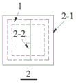
the connecting beam end part components comprise end plates and hinged connecting pieces E, the number of the connecting beam end part components is four, the four connecting beam end part components are respectively connected with two ends of the upper chord member of the square steel pipe and two ends of the lower chord member of the square steel pipe, the centers of the four end plates are respectively aligned with the centers of the sections of the two ends of the upper chord member of the square steel pipe and the sections of the two ends of the lower chord member of the square steel pipe and are fixedly welded on the sections of the two ends of the upper chord member of the square steel pipe and the sections of the two ends of the lower chord member of the square steel pipe, and the hinged connecting pieces E are fixedly welded on the centers of the plate surfaces of the end plates;
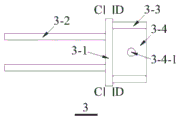
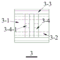
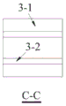
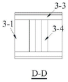
the embedded connecting steel plate comprises a connecting main plate, two embedded steel plates, two transverse stiffening ribs and two vertical stiffening ribs, wherein the two embedded steel plates are symmetrically and fixedly connected to one surface of the connecting main plate to form an embedded part in the embedded connecting steel plates together, the embedded part is embedded into the shear walls on two sides of a truss type connecting beam in advance, the other surface of the connecting main plate is exposed out of the shear walls, the two transverse stiffening ribs and the two vertical stiffening ribs are symmetrically and fixedly connected to the other surface of the connecting main plate, the two vertical stiffening ribs are arranged between the two transverse stiffening ribs, the clear distance between the two transverse stiffening ribs is slightly larger than the height of a hinged connecting piece in an end part component of the connecting beam, the clear distance between the two vertical stiffening ribs is slightly larger than the thickness of the hinged connecting piece E in the end part component of the connecting beam so that the hinged connecting piece E can be inserted into a space surrounded by the two transverse stiffening ribs and the two vertical stiffening ribs, the vertical stiffening ribs are internally provided with a pin hole, the pin hole is the same as the round hole on the hinged connecting piece in size and the circle center of the pin hole is aligned, and the connecting beam end part component is hinged on the embedded connecting steel plate by adopting a pin, so that the whole truss type connecting beam is hinged on the shear walls on two sides.
Preferably, the upper chord member of the square steel pipe, the lower chord member of the square steel pipe, the hinged connecting piece A, the hinged connecting piece B, the hinged connecting piece C and the hinged connecting piece D in the truss type connecting beam under the action of the earthquake, the end part member of the connecting beam and the embedded connecting steel plate are kept in an elastic state, and only the buckling restrained brace A and the buckling restrained brace B enter a plastic state.
The seismic wave energy dissipation method mainly dissipates seismic wave energy by means of plastic deformation of the energy dissipation inner core A and the energy dissipation inner core B, when the truss type connecting beam works normally, the upper chord of the square steel pipe, the lower chord of the square steel pipe and the four hinged connecting pieces in the truss type connecting beam keep elastic states, only the energy dissipation inner core enters a plastic stage, energy dissipation and damage are concentrated on the buckling restrained brace A and the buckling restrained brace B, and replacement after an earthquake is facilitated.
Preferably, the embedded length of the embedded steel plates in the embedded connecting steel plates is required to meet the condition that the adhesive force generated by the contact between the embedded steel plates and concrete is 1.2 times greater than the horizontal pulling force applied to the connecting steel plates, and sufficient safety redundancy is guaranteed.
When the truss type coupling beam normally works, the axial force can be generated at the end part of the coupling beam along the length direction of the coupling beam, so that the embedded steel plate in the embedded shear wall is subjected to outward horizontal tension, the embedded length of the embedded steel plate in the embedded connecting steel plate can meet the condition that the bonding force generated by the contact of the embedded steel plate and concrete is 1.2 times greater than the horizontal tension received by the connecting steel plate, and the truss type coupling beam is ensured to have enough safety redundancy.
Preferably, when the width of the shear wall on two sides of the truss type coupling beam cannot be larger than the pre-buried length of two pre-buried steel plates in the pre-buried connecting steel plates in the shear wall, the pre-buried steel plates with hooks are adopted as the pre-buried steel plates.
In order to ensure enough safety redundancy, the embedding length of the embedded steel plates in the embedded connecting steel plates is required to be 1.2 times that the adhesive force generated by the contact of the embedded steel plates and concrete is larger than the horizontal tensile force applied to the connecting steel plates, when the width of the shear walls on the two sides of the truss type connecting beam cannot meet the embedding length of the two embedded steel plates in the embedded connecting steel plates in the shear wall, the embedded steel plates can adopt the embedded steel plates with hooks, the adhesive force between the embedded steel plates and the concrete is increased, and therefore the requirement is met.
Preferably, the included angles between the buckling restrained brace A and the buckling restrained brace B in the truss type connecting beam and the upper chord member and the lower chord member of the square steel tube are determined according to the main stress trace of the concrete connecting beam with the same size corresponding to the truss type connecting beam under the action of the earthquake.
The angle between the two web members and the upper chord member and the angle between the two web members and the lower chord member in the truss type coupling beam are determined through the main stress trace of the concrete coupling beam under the action of an earthquake, so that the two buckling restrained braces generate the maximum tension and compression deformation when the coupling beam works, and the self energy consumption capability is fully exerted.
Preferably, the energy dissipation cores a and B in the buckling restrained brace a and the buckling restrained brace B are in cylindrical, prismatic, bamboo joint or other applicable forms.
A variety of different buckling-restrained braces may be used in the truss-type coupling beam, including but not limited to round bar energy-dissipating bars as in patent application No. CN201710056141.9, fabricated pure steel type buckling-restrained energy-dissipating braces as in patent application No. CN201320578067.4, and the like.
Preferably, the energy dissipation inner core A and the energy dissipation inner core B in the buckling restrained brace A and the buckling restrained brace B are made of SMA materials.
The energy-consuming inner core of the buckling restrained brace is made of an SMA material, the SMA material has good superelasticity and shape memory capacity, almost no residual deformation exists in the SMA material subjected to proper pretreatment in cyclic loading, and the SMA material can be directly restored to the original position after external stress is unloaded after the proper pretreatment.
Preferably, the upper chord member and the lower chord member of the square steel tube are hollow square steel tubes, hollow round steel tubes, I-shaped steel or steel tube concrete.
The upper chord member and the lower chord member of the square steel tube can adopt various forms including hollow square steel tubes, hollow round steel tubes, I-shaped steel or steel tube concrete, so as to meet the actual bearing capacity requirement.
Preferably, the number of the buckling restrained braces connected between the upper chord member and the lower chord member of the square steel pipe is multiple, and the number is determined according to actual energy consumption requirements.
The buckling restrained brace of suitable quantity is installed according to upper and lower chord length size in fact, can provide different power consumption ability to the structural system of equidimension not to adapt to actual antidetonation and user demand.
Preferably, the buckling restrained brace A and the buckling restrained brace B are a first anti-seismic defense line, and axial deformation occurs firstly in an earthquake; after the shear wall is damaged, the upper chord of the square steel pipe and the lower chord of the square steel pipe form two new small connecting beams between the shear walls, and the two new small connecting beams can continuously bear load and serve as a second defense line.
The buckling restrained brace is arranged to convert the shearing deformation of the common energy-consuming connecting beam into the axial deformation of the buckling restrained brace, so that energy consumption is provided, and the energy consumption is a first anti-seismic defense line; after the buckling restrained brace is damaged, the upper chord and the lower chord become new connecting beams, and the seismic energy can be continuously dissipated, so that the second anti-seismic defense line is formed.
The invention has the following beneficial effects:
1. all components in the truss type replaceable energy dissipation coupling beam with the buckling restrained brace are steel components with conventional sizes, and the steel components are convenient to process, simple to assemble and convenient to produce in quantity.
2. Each part of the truss type replaceable energy dissipation connecting beam with the buckling restrained brace is hinged, and the buckling restrained brace is installed, so that damage under the earthquake action is concentrated on the buckling restrained brace, the energy consumption capability is enhanced, and the truss type replaceable energy dissipation connecting beam is more convenient to maintain and replace after earthquake.
3. The buckling restrained brace in the truss type replaceable energy dissipation coupling beam with the buckling restrained brace weakens the energy of seismic waves through the plastic deformation of the energy dissipation core, the upper chord of the square steel pipe and the lower chord of the square steel pipe in the coupling beam are firstly damaged in an earthquake, the upper chord of the rear steel pipe and the lower chord of the square steel pipe are damaged to form two small coupling beams between shear walls, the two small coupling beams can still bear load, energy dissipation is provided, and an anti-seismic defense line is added.
4. The angle of the buckling restrained brace in the truss type replaceable energy dissipation connecting beam with the buckling restrained brace is determined according to a main stress trace of the concrete connecting beam under the action of an earthquake, so that the buckling restrained brace can be deformed fully, and the energy consumption capability of the connecting beam is optimized.
5. The truss type replaceable energy dissipation connecting beam with the buckling restrained brace can adopt various different buckling restrained braces, and the energy dissipation core can adopt SMA material so as to realize the self-resetting function; the number of the buckling restrained braces can be determined according to the size of the connecting beam and actual requirements, so that the connecting beam can adapt to different conditions, and the anti-seismic property of the connecting beam is improved.
6. The upper chord member and the lower chord member of the square steel tube in the truss type replaceable energy dissipation coupling beam with the buckling restrained brace are not limited to hollow square steel tubes, hollow round steel tubes, I-shaped steel and steel tube concrete can be adopted according to different rigidity requirements of the coupling beam, the practical situation can be adapted, and the shock resistance of the whole structure is improved.
Drawings
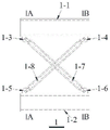
Figure 1 is a plan view of a truss type replaceable energy dissipating coupling beam with buckling restrained braces according to example 1 of the present invention;
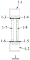
fig. 2 is a plan view of a truss-type coupling beam in the truss-type replaceable energy-dissipating coupling beam with buckling-restrained braces according to example 1 of the present invention;
figure 3 is a side view of a truss-type coupling beam in a truss-type replaceable energy-dissipating coupling beam with buckling-restrained braces according to example 1 of the present invention;
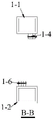
fig. 4 is a sectional view a-a of a truss-type coupling beam in the truss-type replaceable energy-dissipating coupling beam with buckling-restrained braces according to example 1 of the present invention;
figure 5 is a B-B sectional view of the truss type coupling beam in the truss type replaceable energy dissipation coupling beam with buckling restrained braces according to example 1 of the present invention;
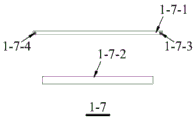
figure 6 is an exploded view of a buckling restrained brace a in a truss type replaceable energy dissipation coupling beam with buckling restrained braces according to embodiment 1 of the invention;
figure 7 is a plan view of a buckling restrained brace B in a truss type replaceable energy dissipating coupling beam with buckling restrained braces according to example 1 of the present invention;
figure 8 is a plan view of an end member of an attachment beam in a truss-type replaceable energy-dissipating attachment beam with buckling-restrained braces according to example 1 of the present invention;
figure 9 is a side view of an end member of an attachment beam in a truss-type replaceable energy-dissipating attachment beam with buckling-restrained braces according to example 1 of the present invention;
fig. 10 is a plan view of a connecting steel plate embedded in a truss-type replaceable energy dissipation coupling beam with buckling restrained braces according to embodiment 1 of the present invention;
figure 11 is a side view of a connecting steel plate embedded in a truss type replaceable energy dissipation connecting beam with buckling restrained braces according to embodiment 1 of the invention;
figure 12 is a C-C sectional view of a connecting steel plate embedded in a truss-type replaceable energy dissipation connecting beam with buckling restrained braces according to embodiment 1 of the present invention;
figure 13 is a D-D cross section of a connecting steel plate embedded in a truss-type replaceable energy dissipation coupling beam with buckling restrained braces according to embodiment 1 of the present invention;
figure 14 is a side view of the truss-type coupling beam in the truss-type replaceable energy-dissipating coupling beam with buckling-restrained braces according to example 2 of the present invention;
figure 15 is a cross-sectional view a-a of a truss-type coupling beam in a truss-type replaceable energy-dissipating coupling beam with buckling-restrained braces according to example 2 of the present invention;
figure 16 is a B-B section view of the truss type coupling beam in the truss type replaceable energy dissipation coupling beam with buckling restrained brace of the embodiment 2 of the invention.
Fig. 17 is a schematic diagram of the principal stress trace of the concrete coupling beam with the same size corresponding to the truss-type coupling beam in the embodiments 1 and 2 of the invention under the action of earthquake.
Detailed Description
The invention is further described with reference to the following figures and detailed description.
Example 1
As shown in FIGS. 1 to 13: the utility model provides a take removable energy dissipation of truss type of bucking restraint support even roof beam, includes that the truss type links roof beam 1, links roof beam end component 2 and pre-buried connecting steel plate 3:
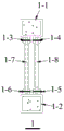
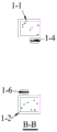
the truss type connecting beam 1 comprises square steel pipe upper chords 1-1, square steel pipe lower chords 1-2, hinged connectors A1-3, hinged connectors B1-4, hinged connectors C1-5, hinged connectors D1-6, buckling restrained braces A1-7 and buckling restrained braces B1-8; the upper chord 1-1 and the lower chord 1-2 of the square steel pipe are respectively used as the upper chord and the lower chord of the truss-type connecting beam 1, the hinged connecting piece A1-3 and the hinged connecting piece B1-4 are respectively and fixedly connected with two ends of the lower surface of the upper chord 1-1 of the square steel pipe, the hinged connecting piece 1-5C and the hinged connecting piece D1-6 are respectively and fixedly connected with two ends of the upper surface of the lower chord 1-2 of the square steel pipe, so that the connecting line of the hinged connecting piece A1-3 and the hinged connecting piece D1-6, the connecting line of the hinged connecting piece B1-4 and the hinged connecting piece C1-5 are in a spatial non-coplanar straight line; the buckling restrained brace A1-7 comprises an energy-consuming inner core A1-7-1, an outer restrained sleeve A1-7-2, a first pin hole A1-7-3 and a second pin hole A1-7-4, wherein the outer restrained sleeve A1-7-2 is sleeved outside the energy-consuming inner core A1-7-1 to prevent the energy-consuming inner core A1-7-1 from buckling in work, the circle centers of round holes in the first pin hole A1-7-3 and the second pin hole A1-7-4 are respectively aligned with the circle centers of round holes in the hinged connector A1-3 and the hinged connector D1-6, the diameters of the round holes are the same, and the round holes are connected through pins, so that the buckling restrained brace A1-7 becomes an oblique web rod in the truss type connecting beam 1; the buckling restrained brace B1-8 comprises an energy-consuming inner core B1-8-1, an outer restraining sleeve B1-8-2, a first pin hole B1-8-3 and a second pin hole B1-8-4, wherein the outer restraining sleeve B1-8-2 is sleeved outside the energy-consuming inner core B1-8-1 to prevent the energy-consuming inner core B1-8-1 from buckling in work, the first pin hole B1-8-3 and the second pin hole B1-8-4 are respectively aligned with the circle centers of round holes in the hinged connecting piece B1-4 and the hinged connecting piece C1-5 and have the same diameter and are connected through pins, so that the buckling restrained brace B1-8 becomes another diagonal web bar in the truss type connecting beam 1, the buckling restrained braces 1-7 and 1-8 are in a cross shape and are not in contact, the axes are straight lines with different surfaces in space; the connecting beam end part component 2 comprises an end plate 2-1 and a hinged connecting piece E2-2, the number of the connecting beam end part components 2 is four, the four connecting beam end part components are respectively connected with two ends of an upper chord 1-1 of a square steel pipe and two ends of a lower chord 1-2 of the square steel pipe, the centers of the four end plates 2-1 are respectively aligned with the centers of the sections of two ends of the upper chord 1-1 of the square steel pipe and the sections of two ends of the lower chord 1-2 of the square steel pipe and are fixedly welded on the sections of two ends of the upper chord 1-1 of the square steel pipe and the lower chord 1-2 of the square steel pipe, and the hinged connecting piece E2-2 is fixedly welded on the center of the plate surface of the end plate 2-1; the embedded connecting steel plate 3 comprises a connecting main plate 3-1, two embedded steel plates 3-2, two transverse stiffening ribs 3-3 and two vertical stiffening ribs 3-4, wherein the two embedded steel plates 3-2 are symmetrically and fixedly connected to one surface of the connecting main plate 3-1 to jointly form an embedded part in the embedded connecting steel plate 3, the embedded part is embedded in shear walls on two sides of a truss type connecting beam 1 in advance, the other surface of the connecting main plate 3-1 needs to be exposed out of the shear walls, the two transverse stiffening ribs 3-3 and the two vertical stiffening ribs 3-4 are symmetrically and fixedly connected to the other surface of the connecting main plate 3-1, the two vertical stiffening ribs 3-4 are arranged between the two transverse stiffening ribs 3-3, the clear distance between the two transverse stiffening ribs 3-3 needs to be slightly larger than the height of a hinged connecting piece 2-2 in the connecting beam end component 2, the clear distance between the two vertical stiffening ribs 3-4 needs to be slightly larger than the thickness of a hinged connecting piece E2-2 in the connecting beam end part member 2, so that the hinged connecting piece E2-2 can be inserted into a space enclosed by the two transverse stiffening ribs 3-3 and the two vertical stiffening ribs 3-4, a pin hole 3-4-1 is arranged in the vertical stiffening rib 3-4, the pin hole 3-4-1 is the same as the round hole in the hinged connecting piece 2-2 in size and the circle center is aligned, the connecting beam end part member 2 is hinged to the embedded connecting steel plate 3 by adopting a pin, and the whole truss type connecting beam 1 is hinged to the shear walls on the two sides.
Under the action of an earthquake, an upper chord 1-1 of a square steel pipe, a lower chord 1-2 of the square steel pipe, a hinge connecting piece A1-3, a hinge connecting piece B1-4, a hinge connecting piece C1-5 and a hinge connecting piece D1-6 in a truss type connecting beam 1 are kept in an elastic state, and only a buckling restrained brace A1-7 and a buckling restrained brace B1-8 enter a plastic state, so that energy consumption and damage are concentrated on the buckling restrained brace A1-7 and the buckling restrained brace B1-8, and the truss type connecting beam is convenient to replace after the earthquake.
The embedded length of the embedded steel plate 3-2 in the embedded connecting steel plate 3 is required to meet the condition that the adhesive force generated by the contact of the embedded steel plate 3-2 and concrete is 1.2 times larger than the horizontal pulling force borne by the connecting steel plate 3, and sufficient safety redundancy is ensured.
When the width of the shear wall at two sides of the truss type coupling beam 1 cannot be larger than the pre-buried length of two pre-buried steel plates 3-2 in the pre-buried connecting steel plates 3 in the shear wall, the pre-buried steel plates 3-2 are pre-buried steel plates with hooks.
The included angles of the buckling restrained brace A1-7 and the buckling restrained brace B1-8 in the truss type connecting beam 1 and the upper chord 1-1 of the square steel tube and the lower chord 1-2 of the square steel tube are determined according to a main stress trace of the concrete connecting beam with the same size corresponding to the truss type connecting beam 1 under the action of an earthquake, so that the buckling restrained brace A1-7 and the buckling restrained brace B1-8 can generate maximum tensile and compressive deformation, and the energy consumption capacity is fully exerted.
The buckling restrained brace A1-7 and the buckling restrained brace B1-8 are provided with an energy dissipation inner core A1-7-1 and an energy dissipation inner core B (1-8-1) which are in cylindrical, prismatic, bamboo joint or other applicable forms. Round bar energy-consuming rods as in the patent application number CN201710056141.9, assembled pure steel type buckling restrained energy-consuming supports as in the patent application number CN201320578067.4 and the like can be adopted;
the buckling restrained brace A1-7 and the buckling restrained brace B1-8, wherein the energy dissipation inner core A1-7-1 and the energy dissipation inner core B1-8-1 are made of SMA materials, so that a self-resetting function is realized.
The number of the buckling restrained braces connected between the upper chord 1-1 of the square steel pipe and the lower chord 1-2 of the square steel pipe is multiple, and the buckling restrained braces are determined according to actual bearing capacity requirements.
Buckling restrained brace A1-7 and buckling restrained brace B1-8 are first anti-seismic defense lines, and axial deformation occurs in the earthquake; after the shear wall is damaged, the upper chord 1-1 of the square steel pipe and the lower chord 1-2 of the square steel pipe form two new small connecting beams between the shear walls, and the two new small connecting beams can continuously bear loads and serve as second defense lines.
Example 2
As shown in FIGS. 14 to 16: the present embodiment is the same as the rest of embodiment 1, except that the upper chord 1-1 and the lower chord 1-2 of the square steel tube in the truss-type coupling beam 1 are made of square steel tube concrete instead of hollow square steel tube.
It should be noted that, for those skilled in the art, without departing from the principle of the present invention, several improvements and modifications can be made, and these improvements and modifications should also be construed as the protection scope of the present invention. All the components not specified in the present embodiment can be realized by the prior art.
Claims (10)
1. The utility model provides a take removable energy dissipation of bucking restraint brace of truss type even roof beam which characterized in that: comprises a truss type connecting beam (1), a connecting beam end part component (2) and an embedded connecting steel plate (3),
the truss type connecting beam (1) comprises a square steel pipe upper chord (1-1), a square steel pipe lower chord (1-2), a hinged connecting piece A (1-3), a hinged connecting piece B (1-4), a hinged connecting piece C (1-5), a hinged connecting piece D (1-6), a buckling restrained brace A (1-7) and a buckling restrained brace B (1-8); the upper chord (1-1) and the lower chord (1-2) of the square steel pipe are respectively used as the upper chord and the lower chord of the truss-type connecting beam (1), the hinged connecting piece A (1-3) and the hinged connecting piece B (1-4) are respectively and fixedly connected with two ends of the lower surface of the upper chord (1-1) of the square steel pipe, the hinged connecting piece C (1-5) and the hinged connecting piece D (1-6) are respectively and fixedly connected with two ends of the upper surface of the lower chord (1-2) of the square steel pipe, so that the connecting lines of the hinged connecting piece A (1-3) and the hinged connecting piece D (1-6), the hinged connecting piece B (1-4) and the hinged connecting piece C (1-5) are mutually in a non-coplanar straight line in space; the buckling restrained brace A (1-7) comprises an energy-consuming inner core A (1-7-1), an outer restrained sleeve A (1-7-2), a first pin hole A (1-7-3) and a second pin hole A (1-7-4), the outer restrained sleeve A (1-7-2) is sleeved outside the energy-consuming inner core A (1-7-1) to prevent the energy-consuming inner core A (1-7-1) from buckling in work, the first pin hole A (1-7-3) and the second pin hole A (1-7-4) are respectively aligned with the circle centers of round holes in the hinged connecting piece A (1-3) and the hinged connecting piece D (1-6) and have the same diameter, the buckling restrained braces A (1-7) are connected through pins to form inclined web members in the truss type connecting beam (1); the buckling restrained brace B (1-8) comprises an energy-consuming inner core B (1-8-1), an outer restrained sleeve B (1-8-2), a first pin hole B (1-8-3) and a second pin hole B (1-8-4), the outer restrained sleeve B (1-8-2) is sleeved outside the energy-consuming inner core B (1-8-1) to prevent the energy-consuming inner core B (1-8-1) from buckling in work, the first pin hole B (1-8-3) and the second pin hole B (1-8-4) are respectively aligned with the circle centers of round holes in the hinged connecting piece B (1-4) and the hinged connecting piece C (1-5) and have the same diameter and are connected through pins, so that the buckling restrained brace B (1-8) becomes another diagonal web member in the truss type connecting beam (1), the buckling restrained braces (1-7) and (1-8) are in a cross shape and are not in contact, and the axes of the buckling restrained braces are in straight lines with different surfaces in space; the connecting beam end part component (2) comprises an end plate (2-1) and a hinged connecting piece E (2-2), the number of the connecting beam end part components (2) is four, the four connecting beam end part components are respectively connected with two ends of the upper chord (1-1) of the square steel pipe and two ends of the lower chord (1-2) of the square steel pipe, the centers of the four end plates (2-1) are respectively aligned with the centers of the sections of two ends of the upper chord (1-1) of the square steel pipe and the sections of two ends of the lower chord (1-2) of the square steel pipe and are fixedly welded on the sections of two ends of the upper chord (1-1) of the square steel pipe and the lower chord (1-2) of the square steel pipe, and the hinged connecting piece E (2-2) is fixedly welded on the center of the plate surface of the end plate (2-1); the embedded connecting steel plate (3) comprises a connecting main plate (3-1), two embedded steel plates (3-2), two transverse stiffening ribs (3-3) and two vertical stiffening ribs (3-4), wherein the two embedded steel plates (3-2) are symmetrically and fixedly connected to one surface of the connecting main plate (3-1) to jointly form an embedded part in the embedded connecting steel plates (3), the embedded part is embedded in shear walls on two sides of the truss type connecting beam (1) in advance, the other surface of the connecting main plate (3-1) needs to be exposed out of the shear walls, the two transverse stiffening ribs (3-3) and the two vertical stiffening ribs (3-4) are symmetrically and fixedly connected to the other surface of the connecting main plate (3-1), and the two vertical stiffening ribs (3-4) are arranged between the two transverse stiffening ribs (3-3), the clear distance between the two transverse stiffening ribs (3-3) is required to be larger than the height of the hinged connecting piece (2-2) in the connecting beam end component (2), the clear distance between the two vertical stiffening ribs (3-4) is required to be larger than the thickness of the hinged connecting piece E (2-2) in the connecting beam end component (2), so that the hinge connection member E (2-2) can be inserted into a space surrounded by the two transverse stiffeners (3-3) and the two vertical stiffeners (3-4), the vertical stiffening ribs (3-4) are internally provided with a pin hole (3-4-1), the pin hole (3-4-1) is the same as the round hole on the hinged connecting piece (2-2) in size and the circle center of the pin hole is aligned, and the connecting beam end part member (2) is hinged on the embedded connecting steel plate (3) by adopting a pin, so that the whole truss type connecting beam (1) is hinged on the shear walls at two sides.
2. The truss type replaceable energy dissipation coupling beam with the buckling restrained brace as claimed in claim 1, wherein: the upper chord (1-1) of the square steel pipe, the lower chord (1-2) of the square steel pipe, the hinged connecting piece A (1-3), the hinged connecting piece B (1-4), the hinged connecting piece C (1-5) and the hinged connecting piece D (1-6) in the truss type connecting beam (1) under the action of an earthquake, the connecting beam end component (2) and the embedded connecting steel plate (3) are kept in an elastic state, and only the buckling restrained brace A (1-7) and the buckling restrained brace B (1-8) enter a plastic state, so that energy consumption and damage are concentrated in the buckling restrained brace A (1-7) and the buckling restrained brace B (1-8), and the truss type connecting beam is convenient to replace after the earthquake.
3. The truss type replaceable energy dissipation coupling beam with the buckling restrained brace as claimed in claim 1, wherein: the embedding length of the embedded steel plate (3-2) in the embedded connecting steel plate (3) is required to meet the condition that the adhesive force generated by the contact of the embedded steel plate (3-2) and concrete is 1.2 times larger than the horizontal tensile force borne by the connecting steel plate (3), and sufficient safety redundancy is ensured.
4. The truss type replaceable energy dissipation coupling beam with the buckling restrained brace as claimed in claim 1, wherein: when the width of the shear wall on the two sides of the truss type coupling beam (1) cannot be larger than the pre-buried length of two pre-buried steel plates (3-2) in the pre-buried connecting steel plates (3) in the shear wall, the pre-buried steel plates (3-2) with hooks are adopted.
5. The truss type replaceable energy dissipation coupling beam with the buckling restrained brace as claimed in claim 1, wherein: the included angles of the buckling restrained brace A (1-7) and the buckling restrained brace B (1-8) in the truss type connecting beam (1) and the upper chord (1-1) and the lower chord (1-2) of the square steel pipe are the same as the main stress trace of the concrete connecting beam with the same size corresponding to the truss type connecting beam (1) under the earthquake action.
6. The truss type replaceable energy dissipation coupling beam with the buckling restrained brace as claimed in claim 1, wherein: the energy dissipation inner core A (1-7-1) and the energy dissipation inner core B (1-8-1) in the buckling restrained brace A (1-7) and the buckling restrained brace B (1-8) are cylindrical, prismatic or bamboo joint-shaped.
7. The truss type replaceable energy dissipation coupling beam with the buckling restrained brace as claimed in claim 1, wherein: the buckling restrained brace A (1-7) and the buckling restrained brace B (1-8) are provided with the energy dissipation inner core A (1-7-1) and the energy dissipation inner core B (1-8-1) which are made of SMA materials, so that the self-resetting function is realized.
8. The truss type replaceable energy dissipation coupling beam with the buckling restrained brace as claimed in claim 1, wherein: the upper chord member (1-1) and the lower chord member (1-2) of the square steel tube are hollow square steel tubes, hollow round steel tubes, I-shaped steel or steel tube concrete.
9. The truss type replaceable energy dissipation coupling beam with the buckling restrained brace as claimed in claim 1, wherein: the number of the buckling restrained braces connected between the upper chord (1-1) of the square steel pipe and the lower chord (1-2) of the square steel pipe is multiple.
10. The truss type replaceable energy dissipation coupling beam with the buckling restrained brace as claimed in claim 1, wherein: the buckling restrained brace A (1-7) and the buckling restrained brace B (1-8) are a first anti-seismic defense line and are axially deformed in an earthquake; after the shear wall is damaged, the upper chord (1-1) and the lower chord (1-2) of the square steel pipe form two new small connecting beams between the shear walls, and the two new small connecting beams can continuously bear loads and serve as second defense lines.
Priority Applications (1)
| Application Number | Priority Date | Filing Date | Title |
|---|---|---|---|
| CN202110512453.2A CN113175117A (en) | 2021-05-11 | 2021-05-11 | Truss type replaceable energy dissipation connecting beam with buckling restrained brace |
Applications Claiming Priority (1)
| Application Number | Priority Date | Filing Date | Title |
|---|---|---|---|
| CN202110512453.2A CN113175117A (en) | 2021-05-11 | 2021-05-11 | Truss type replaceable energy dissipation connecting beam with buckling restrained brace |
Publications (1)
| Publication Number | Publication Date |
|---|---|
| CN113175117A true CN113175117A (en) | 2021-07-27 |
Family
ID=76929244
Family Applications (1)
| Application Number | Title | Priority Date | Filing Date |
|---|---|---|---|
| CN202110512453.2A Pending CN113175117A (en) | 2021-05-11 | 2021-05-11 | Truss type replaceable energy dissipation connecting beam with buckling restrained brace |
Country Status (1)
| Country | Link |
|---|---|
| CN (1) | CN113175117A (en) |
Cited By (5)
| Publication number | Priority date | Publication date | Assignee | Title |
|---|---|---|---|---|
| CN109853779A (en) * | 2019-01-24 | 2019-06-07 | 重庆大学 | It is a kind of containing swing column and the full swinging structure system and its construction method of waving wall |
| CN112709344A (en) * | 2020-12-28 | 2021-04-27 | 重庆大学 | X-shaped connection double-limb buckling-restrained brace |
| CN113818739A (en) * | 2021-11-01 | 2021-12-21 | 重庆大学 | Staged yield self-resetting connecting beam column and application and staged energy consumption method thereof |
| CN116290375A (en) * | 2023-05-24 | 2023-06-23 | 中铁城建集团第一工程有限公司 | Anti-seismic buckling support system and support method thereof |
| CN116607703A (en) * | 2023-07-14 | 2023-08-18 | 中国船舶集团国际工程有限公司 | Construction method of large-span truss building structure and large-span truss building structure |
Citations (9)
| Publication number | Priority date | Publication date | Assignee | Title |
|---|---|---|---|---|
| JP2006132203A (en) * | 2004-11-05 | 2006-05-25 | Asanuma Corp | Seismic stud structure combined with brace |
| US20080289267A1 (en) * | 2007-05-22 | 2008-11-27 | Skidmore Owings & Merrill Llp | Seismic structural device |
| CN204919852U (en) * | 2015-07-07 | 2015-12-30 | 杭州天元建筑设计研究院有限公司 | Company's girder construction of steel plate concrete shear force wall |
| CN107605064A (en) * | 2017-10-30 | 2018-01-19 | 南京百西思建筑科技有限公司 | A kind of anti-buckling support coupling beam of assembled X-shaped |
| CN206957055U (en) * | 2017-07-10 | 2018-02-02 | 湖南大学 | A kind of replaceable steel truss high spin system superimposed sheet composite coupling beams |
| CN108049690A (en) * | 2018-02-02 | 2018-05-18 | 中国地震局工程力学研究所 | A kind of new shearing steel truss coupling beam for assembling replacement |
| CN110792188A (en) * | 2019-12-03 | 2020-02-14 | 浙江科技学院 | Replaceable coupling beam with double safety mechanisms |
| CN112160638A (en) * | 2020-10-28 | 2021-01-01 | 西安建筑科技大学 | Double-connecting-beam structure with buckling restrained brace and construction method thereof |
| CN114293674A (en) * | 2022-01-24 | 2022-04-08 | 河北科技大学 | Connecting beam with SMA friction composite damper and SMA friction composite damper |
-
2021
- 2021-05-11 CN CN202110512453.2A patent/CN113175117A/en active Pending
Patent Citations (9)
| Publication number | Priority date | Publication date | Assignee | Title |
|---|---|---|---|---|
| JP2006132203A (en) * | 2004-11-05 | 2006-05-25 | Asanuma Corp | Seismic stud structure combined with brace |
| US20080289267A1 (en) * | 2007-05-22 | 2008-11-27 | Skidmore Owings & Merrill Llp | Seismic structural device |
| CN204919852U (en) * | 2015-07-07 | 2015-12-30 | 杭州天元建筑设计研究院有限公司 | Company's girder construction of steel plate concrete shear force wall |
| CN206957055U (en) * | 2017-07-10 | 2018-02-02 | 湖南大学 | A kind of replaceable steel truss high spin system superimposed sheet composite coupling beams |
| CN107605064A (en) * | 2017-10-30 | 2018-01-19 | 南京百西思建筑科技有限公司 | A kind of anti-buckling support coupling beam of assembled X-shaped |
| CN108049690A (en) * | 2018-02-02 | 2018-05-18 | 中国地震局工程力学研究所 | A kind of new shearing steel truss coupling beam for assembling replacement |
| CN110792188A (en) * | 2019-12-03 | 2020-02-14 | 浙江科技学院 | Replaceable coupling beam with double safety mechanisms |
| CN112160638A (en) * | 2020-10-28 | 2021-01-01 | 西安建筑科技大学 | Double-connecting-beam structure with buckling restrained brace and construction method thereof |
| CN114293674A (en) * | 2022-01-24 | 2022-04-08 | 河北科技大学 | Connecting beam with SMA friction composite damper and SMA friction composite damper |
Non-Patent Citations (2)
| Title |
|---|
| 周云: "可更换连梁抗震性能研究与应用进展", 《工程抗震与加固改造》 * |
| 郭彦林等: "防屈曲支撑的型式、设计理论与应用研究进展", 《工程力学》 * |
Cited By (9)
| Publication number | Priority date | Publication date | Assignee | Title |
|---|---|---|---|---|
| CN109853779A (en) * | 2019-01-24 | 2019-06-07 | 重庆大学 | It is a kind of containing swing column and the full swinging structure system and its construction method of waving wall |
| CN109853779B (en) * | 2019-01-24 | 2023-08-22 | 重庆大学 | Full-swing structure system containing swing column and swing wall and construction method thereof |
| CN112709344A (en) * | 2020-12-28 | 2021-04-27 | 重庆大学 | X-shaped connection double-limb buckling-restrained brace |
| CN112709344B (en) * | 2020-12-28 | 2024-03-01 | 重庆大学 | X-shaped connection double-limb buckling restrained brace |
| CN113818739A (en) * | 2021-11-01 | 2021-12-21 | 重庆大学 | Staged yield self-resetting connecting beam column and application and staged energy consumption method thereof |
| CN116290375A (en) * | 2023-05-24 | 2023-06-23 | 中铁城建集团第一工程有限公司 | Anti-seismic buckling support system and support method thereof |
| CN116290375B (en) * | 2023-05-24 | 2023-08-18 | 中铁城建集团第一工程有限公司 | Anti-seismic buckling support system and support method thereof |
| CN116607703A (en) * | 2023-07-14 | 2023-08-18 | 中国船舶集团国际工程有限公司 | Construction method of large-span truss building structure and large-span truss building structure |
| CN116607703B (en) * | 2023-07-14 | 2023-10-24 | 中国船舶集团国际工程有限公司 | Construction method of large-span truss building structure and large-span truss building structure |
Similar Documents
| Publication | Publication Date | Title |
|---|---|---|
| CN113175117A (en) | Truss type replaceable energy dissipation connecting beam with buckling restrained brace | |
| WO2022037530A1 (en) | Self-resetting buckling-restrained brace and energy consumption method therefor | |
| CN105256913B (en) | A kind of anti-buckling support of shape memory alloy twisted wire Self-resetting friction | |
| US11808026B2 (en) | Resilient prestress-free steel structure formed by combining pin-ended columns with elastic centering beam | |
| CN110924539B (en) | Self-resetting steel pipe concrete column-steel beam joint connecting device | |
| CN109339237B (en) | Self-resetting energy dissipation node of steel beam-concrete column | |
| CN215166514U (en) | Replaceable steel frame energy dissipation beam column node after earthquake based on inverted suspension connection | |
| CN112392163A (en) | Multistage self-recovery type energy dissipation support and energy dissipation method thereof | |
| CN113175116A (en) | Truss type replaceable energy dissipation connecting beam with friction energy dissipation support | |
| CN105926795B (en) | A kind of sleeve pipe constraining anti-buckling support with symmetrical initial imperfection | |
| CN110295780B (en) | Multi-order yielding double-tube constraint type self-resetting buckling restrained brace device | |
| CN205444463U (en) | Damping wall based on steel structure beam and column mosaic structure | |
| CN113123454B (en) | Column-connected double-energy-consumption assembled concrete frame system and construction method | |
| CN112411784A (en) | Stay cable type energy dissipation support and energy dissipation method thereof | |
| CN106049952A (en) | Buckling control support with bidirectional pyramid-shaped energy dissipation units at ends | |
| CN214497935U (en) | Stay cable type energy dissipation support | |
| CN106049699B (en) | A kind of casing constraining anti-buckling support with staggeredly pyramid energy consumption unit | |
| CN112761278B (en) | Slotting energy-consuming steel pipe shear wall with hybrid damper | |
| CN112502307A (en) | Self-recovery type energy dissipation support and energy dissipation method thereof | |
| CN112144690B (en) | Bending shear mixed type square steel pipe damper and manufacturing method | |
| CN210369407U (en) | Building shock attenuation power consumption structure | |
| CN214272474U (en) | Multistage self-recovery type energy dissipation support | |
| CN214497937U (en) | Self-recovery type energy dissipation support | |
| CN214497936U (en) | Multistage inhaul cable type energy dissipation support | |
| CN209817153U (en) | Anti-seismic energy-consumption T-shaped reinforcing node of steel plate |
Legal Events
| Date | Code | Title | Description |
|---|---|---|---|
| PB01 | Publication | ||
| PB01 | Publication | ||
| SE01 | Entry into force of request for substantive examination | ||
| SE01 | Entry into force of request for substantive examination |