CN113168071B - Camera actuator, camera module, and camera mounting device - Google Patents
Camera actuator, camera module, and camera mounting device Download PDFInfo
- Publication number
- CN113168071B CN113168071B CN201980071590.8A CN201980071590A CN113168071B CN 113168071 B CN113168071 B CN 113168071B CN 201980071590 A CN201980071590 A CN 201980071590A CN 113168071 B CN113168071 B CN 113168071B
- Authority
- CN
- China
- Prior art keywords
- magnet
- actuator
- coil
- lens
- fixing
- Prior art date
- Legal status (The legal status is an assumption and is not a legal conclusion. Google has not performed a legal analysis and makes no representation as to the accuracy of the status listed.)
- Active
Links
Images


Classifications
-
- G—PHYSICS
- G02—OPTICS
- G02B—OPTICAL ELEMENTS, SYSTEMS OR APPARATUS
- G02B7/00—Mountings, adjusting means, or light-tight connections, for optical elements
- G02B7/02—Mountings, adjusting means, or light-tight connections, for optical elements for lenses
- G02B7/04—Mountings, adjusting means, or light-tight connections, for optical elements for lenses with mechanism for focusing or varying magnification
- G02B7/08—Mountings, adjusting means, or light-tight connections, for optical elements for lenses with mechanism for focusing or varying magnification adapted to co-operate with a remote control mechanism
-
- G—PHYSICS
- G03—PHOTOGRAPHY; CINEMATOGRAPHY; ANALOGOUS TECHNIQUES USING WAVES OTHER THAN OPTICAL WAVES; ELECTROGRAPHY; HOLOGRAPHY
- G03B—APPARATUS OR ARRANGEMENTS FOR TAKING PHOTOGRAPHS OR FOR PROJECTING OR VIEWING THEM; APPARATUS OR ARRANGEMENTS EMPLOYING ANALOGOUS TECHNIQUES USING WAVES OTHER THAN OPTICAL WAVES; ACCESSORIES THEREFOR
- G03B13/00—Viewfinders; Focusing aids for cameras; Means for focusing for cameras; Autofocus systems for cameras
- G03B13/32—Means for focusing
- G03B13/34—Power focusing
- G03B13/36—Autofocus systems
-
- B—PERFORMING OPERATIONS; TRANSPORTING
- B06—GENERATING OR TRANSMITTING MECHANICAL VIBRATIONS IN GENERAL
- B06B—METHODS OR APPARATUS FOR GENERATING OR TRANSMITTING MECHANICAL VIBRATIONS OF INFRASONIC, SONIC, OR ULTRASONIC FREQUENCY, e.g. FOR PERFORMING MECHANICAL WORK IN GENERAL
- B06B1/00—Methods or apparatus for generating mechanical vibrations of infrasonic, sonic, or ultrasonic frequency
- B06B1/02—Methods or apparatus for generating mechanical vibrations of infrasonic, sonic, or ultrasonic frequency making use of electrical energy
- B06B1/04—Methods or apparatus for generating mechanical vibrations of infrasonic, sonic, or ultrasonic frequency making use of electrical energy operating with electromagnetism
-
- G—PHYSICS
- G02—OPTICS
- G02B—OPTICAL ELEMENTS, SYSTEMS OR APPARATUS
- G02B27/00—Optical systems or apparatus not provided for by any of the groups G02B1/00 - G02B26/00, G02B30/00
- G02B27/64—Imaging systems using optical elements for stabilisation of the lateral and angular position of the image
- G02B27/646—Imaging systems using optical elements for stabilisation of the lateral and angular position of the image compensating for small deviations, e.g. due to vibration or shake
-
- G—PHYSICS
- G02—OPTICS
- G02B—OPTICAL ELEMENTS, SYSTEMS OR APPARATUS
- G02B7/00—Mountings, adjusting means, or light-tight connections, for optical elements
- G02B7/02—Mountings, adjusting means, or light-tight connections, for optical elements for lenses
- G02B7/04—Mountings, adjusting means, or light-tight connections, for optical elements for lenses with mechanism for focusing or varying magnification
- G02B7/09—Mountings, adjusting means, or light-tight connections, for optical elements for lenses with mechanism for focusing or varying magnification adapted for automatic focusing or varying magnification
-
- G—PHYSICS
- G03—PHOTOGRAPHY; CINEMATOGRAPHY; ANALOGOUS TECHNIQUES USING WAVES OTHER THAN OPTICAL WAVES; ELECTROGRAPHY; HOLOGRAPHY
- G03B—APPARATUS OR ARRANGEMENTS FOR TAKING PHOTOGRAPHS OR FOR PROJECTING OR VIEWING THEM; APPARATUS OR ARRANGEMENTS EMPLOYING ANALOGOUS TECHNIQUES USING WAVES OTHER THAN OPTICAL WAVES; ACCESSORIES THEREFOR
- G03B3/00—Focusing arrangements of general interest for cameras, projectors or printers
- G03B3/10—Power-operated focusing
-
- G—PHYSICS
- G03—PHOTOGRAPHY; CINEMATOGRAPHY; ANALOGOUS TECHNIQUES USING WAVES OTHER THAN OPTICAL WAVES; ELECTROGRAPHY; HOLOGRAPHY
- G03B—APPARATUS OR ARRANGEMENTS FOR TAKING PHOTOGRAPHS OR FOR PROJECTING OR VIEWING THEM; APPARATUS OR ARRANGEMENTS EMPLOYING ANALOGOUS TECHNIQUES USING WAVES OTHER THAN OPTICAL WAVES; ACCESSORIES THEREFOR
- G03B30/00—Camera modules comprising integrated lens units and imaging units, specially adapted for being embedded in other devices, e.g. mobile phones or vehicles
-
- G—PHYSICS
- G03—PHOTOGRAPHY; CINEMATOGRAPHY; ANALOGOUS TECHNIQUES USING WAVES OTHER THAN OPTICAL WAVES; ELECTROGRAPHY; HOLOGRAPHY
- G03B—APPARATUS OR ARRANGEMENTS FOR TAKING PHOTOGRAPHS OR FOR PROJECTING OR VIEWING THEM; APPARATUS OR ARRANGEMENTS EMPLOYING ANALOGOUS TECHNIQUES USING WAVES OTHER THAN OPTICAL WAVES; ACCESSORIES THEREFOR
- G03B5/00—Adjustment of optical system relative to image or object surface other than for focusing
-
- H—ELECTRICITY
- H02—GENERATION; CONVERSION OR DISTRIBUTION OF ELECTRIC POWER
- H02K—DYNAMO-ELECTRIC MACHINES
- H02K41/00—Propulsion systems in which a rigid body is moved along a path due to dynamo-electric interaction between the body and a magnetic field travelling along the path
- H02K41/02—Linear motors; Sectional motors
- H02K41/035—DC motors; Unipolar motors
- H02K41/0352—Unipolar motors
- H02K41/0354—Lorentz force motors, e.g. voice coil motors
- H02K41/0356—Lorentz force motors, e.g. voice coil motors moving along a straight path
-
- H—ELECTRICITY
- H04—ELECTRIC COMMUNICATION TECHNIQUE
- H04N—PICTORIAL COMMUNICATION, e.g. TELEVISION
- H04N23/00—Cameras or camera modules comprising electronic image sensors; Control thereof
-
- G—PHYSICS
- G03—PHOTOGRAPHY; CINEMATOGRAPHY; ANALOGOUS TECHNIQUES USING WAVES OTHER THAN OPTICAL WAVES; ELECTROGRAPHY; HOLOGRAPHY
- G03B—APPARATUS OR ARRANGEMENTS FOR TAKING PHOTOGRAPHS OR FOR PROJECTING OR VIEWING THEM; APPARATUS OR ARRANGEMENTS EMPLOYING ANALOGOUS TECHNIQUES USING WAVES OTHER THAN OPTICAL WAVES; ACCESSORIES THEREFOR
- G03B2205/00—Adjustment of optical system relative to image or object surface other than for focusing
- G03B2205/0007—Movement of one or more optical elements for control of motion blur
-
- G—PHYSICS
- G03—PHOTOGRAPHY; CINEMATOGRAPHY; ANALOGOUS TECHNIQUES USING WAVES OTHER THAN OPTICAL WAVES; ELECTROGRAPHY; HOLOGRAPHY
- G03B—APPARATUS OR ARRANGEMENTS FOR TAKING PHOTOGRAPHS OR FOR PROJECTING OR VIEWING THEM; APPARATUS OR ARRANGEMENTS EMPLOYING ANALOGOUS TECHNIQUES USING WAVES OTHER THAN OPTICAL WAVES; ACCESSORIES THEREFOR
- G03B2205/00—Adjustment of optical system relative to image or object surface other than for focusing
- G03B2205/0053—Driving means for the movement of one or more optical element
- G03B2205/0069—Driving means for the movement of one or more optical element using electromagnetic actuators, e.g. voice coils
Abstract
The actuator for the camera comprises: a stationary-side member; a movable-side member that is provided so as to be displaceable relative to the fixed-side member and holds the lens portion; and a drive section that displaces the movable-side member in a plane including a first direction and a second direction orthogonal to the first direction, wherein the movable-side member includes a magnet fixing section for fixing the magnet section so as to face the fixed-side member, the magnet section is used for detecting a position of the movable-side member in either one of the first direction and the second direction, and a mounting surface of the magnet fixing section on which the magnet section is mounted is made of metal.
Description
Technical Field
The invention relates to an actuator for a camera, a camera module and a camera mounting device.
Background
Conventionally, a thin camera-mounted device such as a smartphone or a digital camera, which is mounted with a camera module, is known. The camera module includes: a lens unit having one or more lenses, and an image pickup device for picking up an image of an object formed by the lens unit (see patent document 1).
The camera module disclosed in patent document 1 includes: an Auto Focus function (hereinafter referred to as "AF function") for automatically focusing when an object is photographed, and a shake correction function (hereinafter referred to as "OIS function") for correcting hand shake generated in a camera. Such a camera module includes an actuator for autofocus for moving the lens unit in the direction of the optical axis and an actuator for shake correction for moving the lens unit in a plane orthogonal to the direction of the optical axis.
In addition, in the camera module disclosed in patent document 2, each of the autofocus actuator and the shake correction actuator is constituted by a voice coil motor having: a magnet portion fixed to a movable-side member that holds the lens portion; and a coil portion provided on the fixed-side member in a state of facing the magnet portion.
Documents of the prior art
Patent document
Patent document 1: japanese laid-open patent publication No. 2015-92285
Patent document 2: international publication No. 2016/166730
Disclosure of Invention
Problems to be solved by the invention
As disclosed in patent document 2, it is desirable for a camera module to have the following configuration: the magnet part constituting the voice coil motor is not easily detached from the movable-side member even when the camera module is subjected to an impact.
The invention aims to provide an actuator for a camera, a camera module and a camera carrying device, which can prevent a magnet part forming a voice coil motor from falling off from a movable side member.
Means for solving the problems
One embodiment of an actuator for a camera according to the present invention includes: a stationary-side member; a movable-side member that is provided so as to be displaceable relative to the fixed-side member and holds the lens portion; and a driving section that displaces the movable-side member in a plane including a first direction and a second direction orthogonal to the first direction. The movable-side member includes a magnet fixing portion for fixing a magnet portion for detecting a position of the movable-side member in either one of the first direction and the second direction so as to face the fixed-side member. The magnet fixing portion is made of metal and has a mounting surface on which the magnet portion is mounted.
One aspect of the camera module of the present invention includes: the above-described actuator for a camera; and an image pickup element disposed at a rear stage of the lens section.
One aspect of the camera mounting device of the present invention includes: the above-described camera module; and a control unit that controls the camera module.
Effects of the invention
According to the present invention, the magnet portion constituting the voice coil motor can be prevented from falling off the movable-side member.
Drawings
Fig. 1 is a perspective view of a camera module according to an embodiment of the present invention.
Fig. 2 is a perspective view showing a prism module of the camera module with parts omitted.
Fig. 3 is a perspective view of the prism module, in which some components are omitted, when viewed from a different angle from fig. 2.
Fig. 4 is a perspective view of a state in which the stand is assembled to the first chassis.
Fig. 5 is a perspective view of the first chassis.
Fig. 6 is a top view of the first base.
Fig. 7 is a perspective view showing only the rocking support spring taken out.
Fig. 8 is a cross-sectional view of a prism module.
Fig. 9A is a perspective view of the lens module.
Fig. 9B is a perspective view of the lens module viewed from a different angle than fig. 9A.
Fig. 10A is a perspective view of a lens module with parts omitted.
Fig. 10B is a perspective view showing a lens module with parts omitted in a state of being viewed from a different angle from fig. 10A.
Fig. 11 is a side view of the lens module with the second mount omitted.
Fig. 12 is a side view showing the lens module from which the second mount is omitted, as viewed from the side opposite to fig. 11.
Fig. 13 is a bottom view of the lens guide.
FIG. 14A shown in FIG. 11 for a lens module with a part of the components omitted 1 Arrow view of (a).
Fig. 15 is a perspective view showing the spring taken out so as to maintain the arrangement in the assembled state.
Fig. 16 is a perspective view of the FPC, AF actuator, and rear OIS actuator.
Fig. 17 is a perspective view of the FPC, AF actuator, and rear OIS actuator viewed from a different angle than fig. 16.
Fig. 18 is a circuit diagram of the AF drive control circuit.
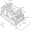
Fig. 19 is a perspective view of the second chassis.
Fig. 20 is a perspective view of the second chassis viewed from a different angle than fig. 19.
Fig. 21A is an exploded perspective view of the second chassis.
Fig. 21B is a top view of the second chassis.
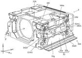
Fig. 22 is a perspective view of the second base, the AF actuator, and the rear OIS actuator.
Fig. 23 is a perspective view of the second base, the AF actuator, and the rear OIS actuator viewed from a different angle from fig. 22.
Fig. 24A is a top view of the fixing plate.
FIG. 24B is A shown in FIG. 24A 1 Arrow view of (a).
Fig. 24C is a perspective view of the fixing plate.
Fig. 25A is a plan view of the shielding plate.
FIG. 25B is A shown in FIG. 25A 2 A view of the arrows.
Fig. 25C is a perspective view of the shield plate.
Fig. 26A is a plan view of a lens module with parts omitted.
Fig. 26B is a schematic top view of the lens guide and the reference member.
Fig. 27A and 27B are front and rear views showing an example of a camera mounting device on which a camera module is mounted.
Fig. 28A and 28B are diagrams illustrating an automobile as a camera mounting device on which an in-vehicle camera module is mounted.
Detailed Description
Hereinafter, embodiments of the present invention will be described in detail with reference to the drawings.
[ embodiment 1]
A camera module according to embodiment 1 of the present invention will be described with reference to fig. 1 to 26B. Hereinafter, a description will be given of a specific configuration of the prism module 2, the lens module 3, and the image pickup device module 4 included in the camera module 1, after an outline of the camera module 1 is described. The camera actuator, the camera module, and the camera mounting device according to the present invention may have all or no part of the structure described below.
< Camera Module >
The camera module 1 is mounted on a thin camera-mounted device such as a smartphone M (see fig. 27A and 27B), a mobile phone, a digital camera, a notebook computer, a tablet terminal, a portable game machine, or an in-vehicle camera.
Hereinafter, each part constituting the camera module 1 of the present embodiment will be described with reference to a state in which the camera module 1 is incorporated. In the description of the configuration of the camera module 1 according to the present embodiment, the orthogonal coordinate systems (X, Y, Z) shown in the drawings are used. The X direction corresponds to an example of the first direction. The Y direction corresponds to an example of the second direction.
For example, the camera module 1 is mounted such that, when the camera mounting device actually performs imaging, the X direction is the left-right direction, the Y direction is the up-down direction, and the Z direction is the front-back direction. As indicated by a one-dot chain line α (also referred to as a first optical axis) in fig. 2, light from the subject enters the prism 23 of the prism module 2 from the + side (positive side) in the Z direction. As shown by a one-dot chain line β (also referred to as a second optical axis) in fig. 2 and 10A, the light incident on the prism 23 is bent by an optical path bending surface 231 (see fig. 8) of the prism 23, and is guided to the lens portion 33 of the lens module 3 disposed at a rear stage (i.e., on the X direction + side) of the prism 23. Then, the image of the subject formed by the lens portion 33 (see fig. 10A) is picked up by the image pickup device module 4 (see fig. 1) disposed at the rear stage of the lens module 3.
The camera module 1 described above performs shake correction (OIS: optical Image Stabilization) by the first shake correction device 24 (see fig. 2 and 8) incorporated in the prism module 2 and the second shake correction device 35 (see fig. 11 and 12) incorporated in the lens module 3. The camera module 1 performs autofocus by displacing the lens unit 33 in the X direction by the AF device 34 (see fig. 11 and 12) incorporated in the lens module 3.
Next, the prism module 2, the lens module 3, and the image pickup device module 4 included in the camera module 1 according to the present embodiment will be described with reference to fig. 1 to 26B.
< prism Module >
The prism module 2 is described with reference to fig. 1 to 8. The prism module 2 includes a first cover 21, a first base 22, a prism 23, and a first shake correction device 24.
< first cover >
As shown in fig. 1, the first cover 21 is made of, for example, synthetic resin or nonmagnetic metal. Such a first cover 21 is a box-shaped member having both sides in the Z direction and an opening on the + side in the X direction. Light from the subject side can enter the internal space of the first cover 21 through the opening on the Z direction + side of the first cover 21. The first cover 21 as described above is combined from the Z direction + side to a first base 22 described later.
< first base >
The first base 22 will be described with reference to fig. 5 and 6. The first base 22 is a box-shaped member having openings on the Z direction + side and the X direction + side, respectively. The bottom wall 229 on the Z-direction side of the first base 22 has a base-side opening 220.
The first coil 244c and the first hall element 244e of the front-side OIS actuator 244 are disposed in the base-side opening 220.
The first base 22 supports the holder 241 of the first shake correction device 24 so that the holder 241 can swing around a first axis parallel to the Y direction. For this reason, the first base 22 has a first receiving portion 225c and a second receiving portion 225d for holding a swing guide member 245 described later.
The first receiving portion 225c is provided on the first side wall portion 224a on the Y direction + side in the first base 22. On the other hand, the second receiving portion 225d is provided on the Y-direction-side second side wall portion 224b of the first base 22.
Such first receiving portion 225c and second receiving portion 225d have shapes symmetrical to each other in the Y direction. Specifically, the first receiving portion 225c and the second receiving portion 225d are cylindrical recesses that are open only at the end surfaces (upper surfaces) of the first side wall 224a and the second side wall 224b on the Z direction + side, respectively.
The first side wall 224a has a first weir portion 224c1 between the Y-direction inner end edge of the upper surface and the first receiving portion 225c. On the other hand, the second side wall portion 224b has a first dam portion 224c2 between the Y-direction inner end edge of the upper surface and the second receiving portion 225d. The first dam portion 224c1 and the first dam portion 224c2 help prevent the adhesive for fixing the swing guide 245 to the first receiving portion 225c and the second receiving portion 225d from flowing out to the center side in the Y direction, respectively.
The first side wall portion 224a has a second weir portion 224d1 at a portion of the upper surface, which surrounds a portion of the Y-direction outer half of the first receiving portion 225c. On the other hand, the second side wall portion 224b has a second weir portion 224d2 at a portion of the upper surface, which surrounds a part of the Y-direction outer half of the second receiving portion 225d. The second dam portion 224d1 and the second dam portion 224d2 help prevent the adhesive for fixing the swing guide 245 to the first receiving portion 225c and the second receiving portion 225d from flowing out in the Y direction outward, respectively.
The first side wall portion 224a has spring arrangement spaces 224e1 and 224e2 in the portion of the upper surface located outside the second weir portion 224d1 in the Y direction. In the present embodiment, the spring disposition space 224e1 is spaced from the spring disposition space 224e2 in the X direction.
On the other hand, the second side wall portion 224b has spring arrangement spaces 224f1 and 224f2 in the portion of the upper surface that is located outside the second weir portion 224d2 in the Y direction. The spring disposition space 224f1 is spaced apart from the spring disposition space 224f2 in the X direction. In the spring arrangement spaces 224e1 and 224e2 and the spring arrangement spaces 224f1 and 224f2, a part of a continuous portion 243i (specifically, a base end side continuous portion 243 m) of a swinging support spring 243 (see fig. 7) described later is arranged.
The first side wall 224a has three projections 224g1, 224g2, and 224g3 in the order from the X direction + side in the portion of the upper surface located further to the Y direction outer side than the second dam 224d 1. The convex portions 224g1 and the convex portions 224g3 are spaced apart in the X direction and arranged at the same position in the Y direction. The convex portion 224g2 is arranged at a position further to the outside (lower side in fig. 6) than the convex portions 224g1 and 224g3 in the Y direction.
The spring arrangement space 224e1 is provided between the convex portions 224g1 and 224g 2. On the other hand, the spring arrangement space 224e2 is provided between the convex portion 224g2 and the convex portion 224g3.
The second side wall 224b has three projections 224h1, 224h2, and 224h3 in the order from the X direction + side in the portion of the upper surface located further to the Y direction outer side than the second dam 224d 2. The convex portions 224h1 and 224h3 are spaced apart in the X direction and arranged at the same position in the Y direction. Convex portion 224h2 is disposed at a position further to the outside in the Y direction (upper side in fig. 6) than convex portions 224h1 and 224h3.
The spring arrangement space 224f1 is provided between the convex portion 224h1 and the convex portion 224h 2. On the other hand, the spring arrangement space 224f2 is provided between the convex portion 224h2 and the convex portion 224h3.
The first side wall portion 224a and the second side wall portion 224b have a first positioning protrusion 226 and a second positioning protrusion 227, respectively, at both ends in the X direction in the upper surface. The first positioning convex portion 226 and the second positioning convex portion 227 are engaged with a pair of rocking support springs 243 (see fig. 7) described later, respectively, to position the pair of rocking support springs 243.
< first jitter correction device >
The first shake correction device 24 will be described with reference to fig. 4, 5, and 8. The first shake correction device 24 swings the prism 23 about a first axis parallel to the Y direction, thereby performing shake correction in the rotational direction about the first axis. The first shake correction device 24 is disposed in the first housing space 223 (see fig. 8) covered with the first base 22 and the first cover 21. The first shake correction device 24 corresponds to an example of a drive unit.
The first shake correction device 24 includes a pair of swing guide members 245, a pair of swing support springs 243, a holder 241, and a front OIS actuator 244.
In the first shake correction apparatus 24, the holder 241 is supported by the first base 22 so as to be able to swing with respect to the first base 22. In this state, the holder 241 swings around the first axis based on the driving force of the front OIS actuator 244. When the front OIS actuator 244 is driven under the control of the control unit 5 (see fig. 18), the holder 241 and the prism 23 swing about the first axis parallel to the Y direction. Thereby correcting the rotational jitter about the first axis. Next, a specific configuration of each member provided in the first shake correction device 24 will be described.
< swing guide means >
The pair of swing guide members 245 will be described with reference to fig. 5 and 6. The pair of swing guide members 245 are, for example, spheres made of ceramic, metal, or synthetic resin. The swinging guide member 245 of one (i.e., the Y direction + side) of the pair of swinging guide members 245 is disposed in the first receiving portion 225c of the first base 22. On the other hand, the other swing guide member 245 (i.e., the Y-direction side) is disposed in the second receiving portion 225d of the first base 22.
The pair of swing guide members 245 are fixed to the first receiving portion 225c and the second receiving portion 225d by an adhesive, respectively. In this state, the Z-direction + side half of the pair of swing guide members 245 functions as a swing guide surface. The swing guide surface protrudes to the Z direction + side of the first receiving portion 225c and the second receiving portion 225d.
The swing guide member 245 is not limited to a sphere, and may be, for example, a hemisphere, a cylinder, or a semicylinder. The swing guide member 245 may be integral with the first base 22. That is, the swing guide member may be constituted by a part of the first base 22.
< rocking supporting spring >
Referring to fig. 5 and 7, a pair of swing support springs 243 will be described. The pair of rocking support springs 243 support the later-described holder 241 on the first base 22 so that the later-described holder 241 can rock with respect to the first base 22. The pair of rocking support springs 243 are each a metal plate spring, and are disposed on the Z direction + side of the pair of rocking guide members 245.
Next, the rocking support spring 243 of one of the pair of rocking support springs 243 (i.e., the Y direction + side) will be described. The other (i.e., Y-direction-side) rocking support spring 243 is symmetrical to the one rocking support spring 243 in the Y direction.
The one rocking support spring 243 has a pair of first locking portions 243a and 243b, a second locking portion 243c, a twisting permitting portion 243g, and a spring-side guide surface 243h.
One (i.e., X direction + side) first locking portion 243a of the pair of first locking portions 243a, 243b is disposed at the X direction + side end of one of the rocking support springs 243. The first locking portion 243a has a first through hole 243d.
On the other hand, the first locking portion 243b of the other side (i.e., the X-direction side) is disposed at the end of the one rocking support spring 243 on the X-direction side. The other first locking portion 243b has a first through hole 243e. The pair of first locking portions 243a, 243b are connected to each other by a continuous portion 243i extending in the X direction.
The continuous portion 243i has: a continuous member 243j disposed on the X direction + side of the twisting permission portion 243g described later, and a continuous member 243k disposed on the X direction-side of the twisting permission portion 243g. The continuous member 243j connects the twist allowing portion 243g and the first locking portion 243 a. On the other hand, the continuous member 243k connects the twist allowing portion 243g and the first locking portion 243 b.
Next, the continuous portion element 243j will be described. The continuous portion element 243j has a base end side continuous portion 243m and a meandering continuous portion 243n. The base end side continuous portion 243m is connected to the meandering continuous portion 243n.
The base end side continuous portion 243m is provided at an end portion of the continuous portion element 243j closer to the torsion allowing portion 243g. One end (end closer to the twisting permission portion 243 g) of the base end side continuous portion 243m is connected to the twisting permission portion 243g.
The meandering continuous portion 243n has a substantially S-shape. One end (end closer to the torsion permitting portion 243 g) of the meandering continuous portion 243n is connected to the base end side continuous portion 243m. The other end (end on the side farther from the torsion permitting portion 243 g) of the meandering continuous portion 243n is connected to the first locking portion 243 a. The continuous member 243k is symmetrical to the continuous member 243j in the X direction. Therefore, the continuous member 243k is denoted by the same reference numeral as the constituent member of the continuous member 243j, and the description thereof is omitted.
The Z-direction-side surfaces of the pair of first locking portions 243a, 243b are fixed by adhesion to the Z-direction + side end surface of the first side wall portion 224a of the first chassis 22. In this state, the first positioning protrusion 226 of the first base 22 (see fig. 5) is inserted into the first through hole 243d. The second positioning protrusion 227 of the first base 22 is inserted into the first through hole 243e (see fig. 5).
In the other swing support spring 243 (Y direction side), Z direction + side end surfaces of the pair of first locking portions 243a and 243b are fixed to the second side wall portion 224b of the first base 22 by adhesion.
The second locking portion 243c is provided at a portion in the X direction between the first locking portions 243a and 243b with a gap in the X direction. The second locking portion 243c has a pair of second through holes 243f.
The surface of the second locking portion 243c on the Z direction + side is fixed by adhesion to a spring seat surface (not shown) formed on the rear surface of the extension portions 241q, 241r of the holder 241, which will be described later. In this state, a pair of holder-side positioning projections (not shown) formed on the back surfaces of the extension portions 241q and 241r of the holder 241 are inserted into the pair of second through holes 243f, respectively. In the case of the other (Y-direction-side) swinging support spring 243, the surface on the Z-direction + side of the second locking portion 243c is adhesively fixed to a spring seat surface (not shown) formed on the back surface of the extension portions 241q, 241r of the holder 241.
The twisting permitting portion 243g is a plate-like member extending in the Y direction, and connects the X-direction intermediate portion of the continuous portion 243i (specifically, one end of each base-end-side continuous portion 243 m) to the second locking portion 243 c. The twisting allowing portion 243g allows the second locking portion 243c to twist with respect to the first locking portions 243a and 243b by twisting.
The twisting permitting portion 243g permits the relative displacement in the Z direction between the first locking portions 243a and 243b and the second locking portion 243c by elastic deformation.
The spring-side guide surface 243h is formed by the back surface (i.e., the Z-side surface) of the second locking portion 243 c. The spring-side guide surface 243h abuts on the swing guide surface of the swing guide member 245.
The pair of rocking support springs 243 are flat plate-like members as a whole in a free state (also referred to as an unassembled state). On the other hand, in the assembled state, the second locking portion 243c of the pair of rocking support springs 243 is disposed on the Z direction + side of the first locking portions 243a, 243b by elastic deformation of the twisting permitting portion 243g.
Specifically, in the assembled state, the twisting permission portion 243g is elastically deformed so as to be closer to the Z direction + side as the second locking portion 243c becomes closer. Due to such elastic deformation, the spring-side guide surfaces 243h of the pair of rocking support springs 243 urge the rocking guide members 245 to the Z-direction side.
In the assembled state of the pair of rocking support springs 243 as described above, the base end side continuous portions 243m of the pair of rocking support springs 243 are disposed in the spring disposition spaces 224e1, 224e2 and the spring disposition spaces 224f1, 224f2, respectively. Further, in the spring arrangement spaces 224e1 and 224e2 and the spring arrangement spaces 224f1 and 224f2, the gel-like vibration damping member 27 is arranged so as to cover the proximal side continuous portion 243m (see fig. 5).
The vibration damping member 27 is effective for suppressing resonance of the pair of rocking support springs 243. From the viewpoint of suppressing resonance, the vibration damping member 27 is preferably provided in the vicinity of the portion of the pair of rocking support springs 243 that deforms most when used. The portion that is most deformed in use is the twist allowing portion 243g. Therefore, the vibration damping member 27 preferably covers a portion of the pair of rocking support springs 243 closer to the torsion allowing portion 243g.
< Stent >
The holder 241 will be described with reference to fig. 4 and 8. The holder 241 is made of, for example, a synthetic resin, and holds the prism 23 on the first base 22 in a state in which the prism 23 can swing with respect to the first base 22.
The holder 241 includes a mounting surface 241a, a pair of opposing wall portions 241f and 241g, and a pair of extending portions 241q and 241r.
The mounting surface 241a faces the optical path bending surface 231 of the prism 23 from the back side (Z direction-side). The mounting surface 241a has a surface parallel to the optical path bending surface 231, for example. The placement surface 241a is not limited to the configuration of the present embodiment, and may be, for example, a projection having a shape capable of positioning the prism 23.
The pair of opposing wall portions 241f, 241g are plate-like members parallel to the XZ plane, and are arranged in a state spaced apart in the Y direction. The pair of opposing wall portions 241f and 241g are arranged in the Y direction with the mounting surface 241a interposed therebetween.
The pair of protruding portions 241q and 241r are provided on the pair of opposing wall portions 241f and 241g, respectively. The pair of protruding portions 241q and 241r support the holder 241 on the first base 22 so that the holder 241 can swing with respect to the first base 22.
Specifically, one (i.e., Y direction + side) extending portion 241q extends from the Y direction + side surface of the opposing wall portion 241f to the Y direction + side surface.
On the other hand, the other (i.e., Y-direction-side) protruding portion 241r protrudes from the Y-direction-side surface of the opposing wall portion 241g to the Y-direction-side. The pair of projecting portions 241q and 241r have flat spring seat surfaces (not shown) on the back surfaces (i.e., on the Z-direction surfaces). The spring seat surface has a pair of bracket-side positioning projections (not shown) projecting in the Z-direction at two positions spaced apart in the X-direction.
The surfaces on the Z direction + side of the second locking portions 243c of the pair of rocking support springs 243 are respectively bonded and fixed to the spring seat surfaces. In this state, the pair of bracket-side positioning convex portions are inserted into the pair of second through holes 243f of the swinging support spring 243, respectively. With this structure, the holder 241 is supported by the first base 22 so as to be able to swing with respect to the first base 22.
Further, outer end portions of the extension portions 241q, 241r of the holder 241 in the Y direction are positioned closer to the center side in the Y direction than both end surfaces of the first base 22 in the Y direction. Such a structure contributes to downsizing and weight reduction of the holder 241.
< front-side OIS actuator >
With reference to fig. 5 and 8, the front OIS actuator 244 as an actuator for displacing the optical path bending member will be described. The front OIS actuator 244 oscillates the support 241 about the first axis. The first axis is an axis parallel to the Y direction. Specifically, the first axis is an axis parallel to the Y axis through the contact portion between the rocking guide surfaces of the pair of rocking guide members 245 and the spring-side guide surfaces 243h of the pair of rocking support springs 243.
The front OIS actuator 244 is disposed on the back side (i.e., Z-direction side) of the prism 23 and the holder 241 so as to overlap the optical path bending surface 231 of the prism 23 and the holder 241 in the Z-direction (i.e., the direction of the first optical axis). The front OIS actuator 244 includes a first magnet 244a, a first coil 244c, and a first hall element 244e.
The first magnet 244a is fixed to a surface on the back side (i.e., a surface on the Z-direction side) of the holder 241 as the movable-side member. The first magnet 244a is constituted by two magnet elements adjacent in the X direction. These magnet elements are magnetized in the Z direction and have one magnetic pole on one side. The magnetic poles of the magnet elements face in opposite directions to each other.
The first coil 244c and the first hall element 244e are fixed to the front surface (i.e., the surface on the Z direction + side) of a flexible printed circuit board (hereinafter referred to as FPC) 25, and the FPC25 is fixed to the surface on the back surface side of the first base 22.
The first coil 244c and the first hall element 244e are disposed at the base-side opening portion 220 of the first base 22. The first coil 244c is a so-called air-core coil having an oblong shape. The first hall element 244e is disposed radially inward of the first coil 244 c.
The front OIS actuator 244 having the above-described configuration swings the holder 241 about the first axis under the control of the control unit 5 (see fig. 18).
< lens Module >
Next, the lens module 3 will be described with reference to fig. 1 and fig. 9A to 26B. The lens module 3 includes a second cover 31, a second base 32, a lens unit 33, an AF device 34, and a second shake correction device 35.
< second cover >
The second cover 31 will be described with reference to fig. 1, 9A, and 9B. The second cover 31 is, for example, a box-shaped member made of synthetic resin or nonmagnetic metal and having openings on both sides in the X direction and on the Z direction-side (i.e., the back surface side).
Specifically, the second cover 31 includes a top plate 31a, a front plate 31b, a rear plate 31c, a first side plate 31d, and a second side plate 31e.
The top plate 31a is a rectangular plate member. The top plate 31a is disposed on the Z direction + side of the second cover 31. The top plate 31a has a notch 31f at one end in the X direction (an end on the prism module 2 (see fig. 1) side and an end on the X direction side).
A notch 31f is cut out from the X-direction side end of the top plate 31a to the X-direction + side. The notch 31f has a rectangular shape elongated in the Y direction in a plan view.
The front plate 31b is a rectangular plate-like member, and extends from the X-direction side end of the top plate 31a to the Z-direction side. The front plate 31b has a front opening 31g in a portion including the center. The front-side opening 31g has a size that allows the X-side end face of the lens portion 33 to be exposed to the X-side. The light from the prism module 2 enters the lens portion 33 through the front-side opening portion 31g.
The front-side opening 31g is continuous with the notch 31f of the top plate 31 a. Therefore, the edge portion on the Z direction + side of the front-side opening portion 31g does not exist in the corner portion 31h formed by the top plate portion 31a and the front plate portion 31 b. Such a structure can facilitate the processing of the front opening 31g.
The rear plate portion 31c is a rectangular plate-like member, and extends from the X-direction + side end of the top plate portion 31a to the Z-direction side. The rear plate portion 31c has a rear opening 31i in a portion including the central portion. The rear-side opening 31i has a size that allows the X-direction + side end surface of the lens portion 33 to be exposed to the X-direction + side. The light from the lens portion 33 enters the image pickup device module 4 through the rear opening 31i.
The first side plate 31d is a rectangular plate-like member, and extends from the Y-direction + side end of the top plate 31a to the Z-direction side. The second side plate 31e is a rectangular plate-like member, and extends from the Y-side end of the top plate 31a to the Z-side. The second cover 31 as described above is combined with a second base 32 described later from the Z direction + side.
< second base >
The second chassis 32 will be described with reference to fig. 10A, 10B, and 19 to 23. The second chassis 32 is combined with the second cover 31 described above to form a second housing space 32c in which the lens unit 33, the AF device 34, and the second shake correction device 35 can be disposed (see fig. 1).
The lower base member 32a and the upper base member 32b are combined to constitute a second base 32.
The second base 32 has a bottom surface portion 32d and a pair of second side wall portions 32g, 32h. The bottom surface portion 32d has a base portion made of synthetic resin and a metal reinforcing plate 32k insert-molded on the base portion. Such a reinforcing plate 32k contributes to higher rigidity and thinner wall thickness of the bottom surface portion 32 d.
The reinforcing plate 32k of the second base 32 is disposed so as to overlap the lens guide 341 at a position on the Z direction-side of the lens guide 341 to be described later. Specifically, the lens guide 341 is present on the Z direction + side of the reinforcing plate 32k regardless of the position of the lens guide 341 in the range in which the movable range during the operation of the autofocus (i.e., the movable range in the X direction) and the movable range during the operation of the shake correction (i.e., the movable range in the Y direction) are present. Therefore, the front surface (i.e., the surface on the Z direction + side) of the reinforcing plate 32k is always covered with the lens guide 341 and is not exposed. This prevents the reflected light reflected by the reinforcing plate 32k from entering the lens unit 33 and further entering the imaging device of the imaging device module 4, which will be described later.
The second chassis 32 has bottom through holes 32e and 32f (see fig. 19 and 20) in the bottom portion 32d on both sides of the reinforcing plate 32k in the Y direction. As shown in fig. 22 and 23, a first AF coil 346b and a second AF coil 347b of an AF actuator 345 described later are disposed in the bottom through holes 32e and 32f, respectively.
The second side wall portions 32g and 32h extend from both ends of the bottom portion 32d in the Y direction to the + side in the Z direction. As shown in fig. 21A, the second lower wall member 32a1 of the lower base member 32a and the second upper wall member 32b1 of the upper base member 32b are combined to constitute a second side wall portion 32g. In addition, the second lower wall member 32a2 of the lower base member 32a and the second upper wall member 32b2 of the upper base member 32b are combined to constitute a second side wall portion 32h.
As shown in fig. 22 and 23, the second side wall portions 32g, 32h have coil placement portions 32i, 32j, respectively. The first OIS coil 352b and the second OIS coil 353b of the second shake correction device 35, which will be described later, are mounted on the coil mounting portions 32i and 32j, respectively. In the present embodiment, the coil mounting portions 32i and 32j are provided on the upper surfaces of the second upper wall elements 32b1 and 32b2 of the upper base element 32 b.
The coil mounting portion 32i is disposed between the first protruding portion 34a1 and the second protruding portion 34a3 (see fig. 11) of the lens guide 341 in the Z direction. The coil placement portion 32j is disposed between the first protruding portion 34a2 and the second protruding portion 34a4 (see fig. 12) of the lens guide 341 in the Z direction.
The second upper wall member 32B1 of the upper base member 32B has a pair of connection holes 321i, 322i (refer to fig. 21B). The connection hole 321i is provided at the end of the second upper wall element 32b1 on the X direction + side. The connection hole 322i is provided at the X-direction-side end portion of the second upper wall element 32b1. Connection holes 321i, 322i penetrate the second upper wall element 32b1 in the Z direction, respectively. Solder (not shown) is disposed inside the connection holes 321i and 322i.
The solder provided inside the connection holes 321i and 322i connects the first OIS coil 352b disposed in the coil placement portion 32i to the first terminal portion 34d1 (see fig. 11 and 16) of the FPC344 disposed on the Z-direction side of the second upper wall element 32b1. Such solder is supplied to connection holes 321i and 322i from the openings on the Z direction-side of connection holes 321i and 322i by a dispenser or the like.
The second upper wall member 32B2 of the upper base member 32B has a pair of connection holes 321j, 322j (refer to fig. 21B). The connection hole 321j is provided at the end portion of the second upper wall element 32b2 on the X direction + side. The connection hole 322j is provided at the X-direction-side end portion of the second upper wall element 32b2. Connection holes 321j, 322j penetrate the second upper wall element 32b2 in the Z direction, respectively. Solder (not shown) is disposed inside the connection holes 321j and 322j.
The solder provided inside the connection holes 321j, 322j connects the second OIS coil 353b disposed in the coil placement portion 32j and the second terminal portion 34d2 (see fig. 12 and 17) of the FPC344 disposed on the Z-direction side of the second upper wall element 32b2. Such solder is supplied from the openings on the Z-direction sides of the connection holes 321j, 322j to the connection holes 321j, 322j by a dispenser or the like.
As shown in fig. 22, a first AF magnet 346a of an AF actuator 345 described later is disposed between the coil placement portion 32i and the bottom surface portion 32 d. Further, as shown in fig. 23, a second AF magnet 347a of the AF actuator 345 is disposed between the coil placement portion 32j and the bottom surface portion 32 d. The first AF magnet 346a and the second AF magnet 347a are held by a lens guide 341 described later.
In the present embodiment, the bottom through holes 32e and 32f overlap the coil placement portions 32i and 32j at a predetermined distance in the Z direction. Therefore, the first AF coil 346b and the second AF coil 347b disposed in the bottom through holes 32e and 32f overlap the first OIS coil 352b and the second OIS coil 353b placed on the coil placement portions 32i and 32j at a predetermined distance in the Z direction.
The second side wall portion 32g has spring arrangement portions 32m1 and 32m3 (see fig. 10A and 20) for arranging springs 3421 and 3423 (described later) at both ends in the X direction in the Y direction + side surface. On the other hand, the second side wall portion 32h has spring arrangement portions 32m2 and 32m4 (see fig. 10B and 19) for arranging springs 3422 and 3424, which will be described later, at both ends in the X direction in the Y direction-side surface.
The second chassis 32 has a reference portion 32n at the X-direction + side end. The reference portion 32n is a plate-like member provided at the end portion of the second base 32 on the X direction + side. The reference portion 32n has a through hole in the center portion thereof for guiding the light passing through the lens portion 33 to the image pickup device module 4. The side surface on the X direction + side of the reference portion 32n serves as a reference surface in the X direction of the imaging element module 4 described later. Such a reference portion 32n is a member for positioning the image pickup device module 4.
The reference portion 32n has a first reference surface 32n1 (see fig. 20 and 26B) as a reference surface in the X direction of the lens guide 341 to be described later on the X direction-side surface. Such a first reference surface 32n1 is also a reference for calibration described later.
< lens part >
The lens portion 33 is disposed in the second housing space 32c (see fig. 1) in a state of being held by a lens guide 341 described later. As shown in fig. 10A to 12, the lens unit 33 includes a cylindrical lens barrel 33A and one or more lenses 33B held by the lens barrel 33A. For example, the lens unit 33 has a telescopic lens group fixed between the end of the lens barrel 33A on the X-direction side and the end of the lens barrel 33A on the X-direction + side, and having an optical zoom of, for example, three times or more. The structure of the lens unit 33 is not limited to the above-described structure.
< AF device >
The AF device 34 will be described with reference to fig. 10A to 18. The AF device 34 displaces the lens unit 33 in the X direction for the purpose of autofocus. Specifically, the AF device 34 has a lens guide 341, a first support mechanism 342, an FPC344, and an AF actuator 345. The AF device 34 corresponds to an example of a driving unit.
< lens guide >
The lens guide 341 is explained with reference to fig. 11 to 14. Fig. 11 is a view of the lens module 3 in a state where parts are omitted as viewed from the Y direction + side. Fig. 12 is a view of the lens module 3 with parts omitted, as viewed from the Y direction side. Fig. 14 is a view of the lens module 3 in a state where the second base 32 is omitted, as viewed from the X direction-side.
The lens guide 341 has a cylindrical lens holding portion 341a, a pair of first protruding portions 34a1, 34a2, and a pair of second protruding portions 34a3, 34a4. The lens guide 341 is made of synthetic resin as a whole. The lens guide 341 may be made of metal. The lens guide 341 may have a synthetic resin portion and a metal portion.
The lens guide 341 is disposed in the second housing space 32c so as to be displaceable in the X direction (i.e., the direction of the second optical axis) and the Y direction. The lens guide 341 corresponds to an example of the movable-side member. The lens guide 341 may be regarded as an example of a body of the movable-side member.
The lens holding portion 341a has a housing space capable of holding the lens barrel 33A.
The pair of first protruding portions 34a1 and 34a2 extend from two positions on the outer peripheral surface of the cylindrical lens holding portion 341a in directions opposite to each other in the Y-axis direction.
The pair of second protruding portions 34a3 and 34a4 extend in the Y-axis direction from two positions on the outer peripheral surface of the cylindrical lens holding portion 341a on the Z direction + side of the pair of first protruding portions 34a1 and 34a2, respectively.
The first projecting portion 34a1 on one side (Y direction + side) and the second projecting portion 34a3 on one side (Y direction + side) overlap with a space 34b1 therebetween in the Z direction. The other (Y-direction-side) first protruding portion 34a2 and the other (Y-direction-side) second protruding portion 34a4 overlap with a space 34b2 therebetween in the Z-direction.
The lens guide 341 has a first magnet holding portion 34a5 (see fig. 13) that holds a first AF magnet 346a of an AF actuator 345 described later, and a first magnet holding portion 34a6 (see fig. 13) that holds a second AF magnet 347a. Specifically, the first magnet holding portions 34a5 and 34a6 are provided to the pair of first protruding portions 34a1 and 34a2, respectively.
The first magnet holding portions 34a5 and 34a6 are each rectangular frame-shaped with openings on both sides in the Z direction. The first magnet holding portions 34a5 and 34a6 are disposed on the Z-direction sides of the pair of coil mounting portions 32i and 32j (see fig. 22 and 23) of the second base 32. The pair of first magnet holding portions 34a5, 34a6 and the bottom through holes 32e, 32f of the second base 32 are provided on the same straight line parallel to the Z direction. The pair of first magnet holding portions 34a5 and 34a6 are provided on the Z direction + side of the bottom through holes 32e and 32 f.
The lens guide 341 has a second magnet holding portion 34a7 (see fig. 11) that holds a first OIS magnet 352a of the rear OIS actuator 351 described later. In addition, the lens guide 341 has a second magnet holding portion 34a8 (see fig. 12) that holds the second OIS magnet 353a of the rear-side OIS actuator 351. Specifically, the second magnet holding portions 34a7, 34a8 are provided to the pair of second projecting portions 34a3, 34a4, respectively.
The pair of second magnet holding portions 34a7 and 34a8 are recesses each having a Z-direction side opening. The pair of second magnet holding portions 34a7 and 34a8 and the coil mounting portions 32i and 32j of the second base 32 are provided on the same straight line parallel to the Z direction. The pair of second magnet holding portions 34a7 and 34a8 are provided on the Z direction + side of the coil placement portions 32i and 32j.
The lens guide 341 has a third magnet holding portion 34b3 (see fig. 11) that holds the first X-position detection magnet 346d of the AF actuator 345 in the vicinity of the first magnet holding portion 34a5. In addition, the lens guide 341 has a third magnet holding portion 34b4 (see fig. 12) that holds the second X position detecting magnet 347d of the AF actuator 345 in the vicinity of the first magnet holding portion 34a6.
Specifically, the third magnet holding portions 34b3 and 34b4 are provided on the X-direction side of the first magnet holding portions 34a5 and 34a6 out of the pair of first projecting portions 34a1 and 34a2, respectively. The positions of the third magnet holding portions 34b3 and 34b4 are not limited to the above positions as long as they are in the vicinity of the first magnet holding portions 34a5 and 34a6.
The lens guide 341 has a fourth magnet holding portion 34b5 (see fig. 13) that holds the first Y-position detection magnet 352c of the rear-side OIS actuator 351 in the vicinity of the first magnet holding portion 34a5. In addition, the lens guide 341 has a fourth magnet holding portion 34b6 (see fig. 13) that holds the second Y-position detection magnet 353c of the rear-side OIS actuator 351 near the first magnet holding portion 34a6.
Specifically, the pair of fourth magnet holding portions 34b5 and 34b6 are provided at the X direction + side positions of the pair of first projecting portions 34a1 and 34a2 with respect to the first magnet holding portions 34a5 and 34a6, respectively. The positions of the pair of fourth magnet holding portions 34b5 and 34b6 are not limited to the above positions as long as they are in the vicinity of the first magnet holding portions 34a5 and 34a6.
In a state where the lens guide 341 is displaced to the X direction + side by the maximum amount, the X direction + side end surface of the lens guide 341 (hereinafter referred to as a lens guide side reference surface) abuts against the first reference surface 32n1 of the reference portion 32n.
The lens guide side reference surface of the lens guide 341 and the first reference surface 32n1 are flat surfaces parallel to the YZ plane, respectively. Therefore, in a state where the lens guide-side reference surface is in contact with (in surface contact with) the first reference surface 32n1, the lens guide 341 is not inclined in the Y direction and the Z direction with respect to the X direction (i.e., the direction of the second optical axis) (hereinafter referred to as "reference state of the lens guide 341").
< fixing plate >
The fixing plates 36A and 36B will be described with reference to fig. 11 to 13 and fig. 24A to 24C. Fig. 24A to 24C show the fixing plate 36A in an assembled state. The fixing plate 36B is symmetrical in the Y direction with the fixing plate 36A shown in fig. 24A to 24C in the assembled state. The fixing plates 36A and 36B correspond to examples of magnet fixing portions.
The fixing plate 36A is a member for fixing the first X-position detection magnet 346d disposed in the third magnet holding portion 34b3 and the first Y-position detection magnet 352c disposed in the fourth magnet holding portion 34b5 to the lens guide 341. It can be considered that the fixed plates 36A, 36B constitute movable-side members together with the lens guide 341.
As shown in fig. 24A to 24C, the fixing plate 36A includes a first fixing portion 361, a second fixing portion 362, and a connecting portion 363. The fixing plate 36A is made of a nonmagnetic metal as a whole.
The first fixed portion 361 has a plate shape parallel to the XY plane. The first fixing portion 361 has a first fixing surface 364 on an upper surface (surface on the Z direction + side). The first fixing portion 361 has a second fixing surface 365 on a lower surface (a surface on the Z direction side). The first fixing portion 361 has a first locking portion 366a and a second locking portion 366b.
The first locking portion 366a is provided at a first end (end on the X direction + side) of the first fixing portion 361. The second locking portion 366b is provided at a second end (end on the X-direction side) of the first fixing portion 361. The first locking portion 366a and the second locking portion 366b correspond to an example of a locking portion locked to the lens guide 341.
The first fixing portion 361 is disposed above the first Y-position detection magnet 352c, and the first Y-position detection magnet 352c is disposed in the fourth magnet holding portion 34b5.
In addition, in a state where the first fixing portion 361 is disposed with respect to the lens guide 341 as described above, the first locking portion 366a and the second locking portion 366b engage with the lens guide 341 in the Z direction. By such engagement, the movement of the first fixing portion 361 in the Z direction-side with respect to the lens guide 341 is restricted.
The first fixing surface 364 of the first fixing portion 361 is bonded to the lens guide 341 with an adhesive. Specifically, the first fixing surface 364 is bonded to a portion of the lens guide 341 which is provided at a position above the fourth magnet holding portion 34b5 by an adhesive. As described above, the first fixing portion 361 is fixed to the lens guide 341 in a state where movement in the Z direction-side direction is restricted by adhesion and engagement with the lens guide 341.
The second fixing surface 365 of the first fixing portion 361 is adhered to the upper surface of the first Y-position detection magnet 352c by an adhesive. Such a second fixing surface 365 corresponds to an example of a mounting surface. Thus, the first fixing portion 361 fixes the first Y-position detection magnet 352c to the lens guide 341. When the fixing plate 36A is omitted, the mounting surface may be provided directly on the lens guide 341.
The second fixed portion 362 is plate-shaped parallel to the XY plane. The second fixing portion 362 has a third fixing surface 367 on the upper surface (surface on the + side in the Z direction). The second fixing portion 362 has a fourth fixing surface 368 on a lower surface (a surface on the Z direction side). The second fixing portion 362 includes a third locking portion 369a and a fourth locking portion 369b.
The third locking portion 369a is provided at a first end (end on the X direction + side) of the second fixing portion 362. The fourth locking portion 369b is provided at a second end (end on the X-direction side) of the second fixing portion 362. The third locking portion 369a and the fourth locking portion 369b correspond to an example of a locking portion locked to the lens guide 341.
The second fixing portion 362 is disposed above the first X-position detection magnet 346d, and the first X-position detection magnet 346d is disposed in the third magnet holding portion 34b3.
In addition, in a state where the second fixing portion 362 is disposed with respect to the lens guide 341 as described above, the third locking portion 369a and the fourth locking portion 369b are engaged with the lens guide 341 in the Z direction. By such engagement, the movement of the second fixing portion 362 in the Z direction-side with respect to the lens guide 341 is restricted.
The third fixing surface 367 of the second fixing portion 362 is bonded to the lens guide 341 with an adhesive. Specifically, the third fixing surface 367 is bonded to a portion of the lens guide 341, which is provided above the third magnet holding portion 34b3, by an adhesive. As described above, the second fixing portion 362 is fixed to the lens guide 341 in a state in which the movement in the Z direction-side direction is restricted by the adhesion and engagement with the lens guide 341.
Fourth fixing surface 368 of second fixing portion 362 is bonded to the upper surface of first X-position detection magnet 346d by an adhesive. Such a fourth fixing surface 368 corresponds to an example of a mounting surface. Thus, the second fixing portion 362 fixes the first X-position detection magnet 346d to the lens guide 341.
The connection part 363 connects the first fixing part 361 and the second fixing part 362. Specifically, the connection section 363 connects the first fixing section 361 and the second fixing section 362 to each other in the X direction. The connection 363 may be omitted.
In the present embodiment, the connection portion 363 has positioning protrusions 363a, 363b. The positioning protrusions 363a and 363b are provided on a first side surface (inner surface in the Y direction) of the connection portion 363, respectively. The first side surface is a surface facing an outer side surface 76 (see fig. 16) in the Y direction of a shield plate 7A described later in the assembled state.
The positioning protrusions 363a, 363b are provided at two positions spaced apart in the X direction on the first side surface of the connection portion 363. Such positioning projections 363a and 363b project from the first side surface of the connection portion 363 toward the outer side surface 76 of the shield plate 7A.
When the fixed plate 36A is assembled to the lens guide 341, the positioning protrusions 363a and 363b abut against the outer side surface 76 of the shield plate 7A, and guide the assembly of the fixed plate 36A. Such positioning protrusions 363a, 363b contribute to improvement in efficiency of the work of assembling the fixed plate 36A. In the assembled state, the positioning projections 363a and 363b are spaced apart from the outer side surface 76 of the shield plate 7A. In other words, in the assembled state, there is a gap in the Y direction between the positioning protrusions 363a, 363b and the outer side surface 76 of the shield plate 7A.
In the fixing plate 36A, the surface (second fixing surface 365) bonded to the first Y-position detection magnet 352c and the surface (fourth fixing surface 368) bonded to the first X-position detection magnet 346d may be made of metal, and the other portions may be made of nonmetal (e.g., synthetic resin).
The fixing plate 36B is a member for fixing the second X-position detection magnet 347d disposed in the third magnet holding portion 34B4 and the second Y-position detection magnet 353c disposed in the fourth magnet holding portion 34B6 to the lens guide 341. It can be considered that the fixed plate 36B constitutes a movable-side member together with the lens guide 341.
The fixing plate 36B has a first fixing portion 361, a second fixing portion 362, and a connecting portion 363, similarly to the fixing plate 36A. The fixing plate 36B is made of a nonmagnetic metal as a whole. The structure of the fixing plate 36B is the same as that of the fixing plate 36A, and therefore, the description of the structure is omitted.
The first fixing portion 361 of the fixing plate 36B is disposed above the second Y-position detection magnet 353c, and the second Y-position detection magnet 353c is disposed in the fourth magnet holding portion 34B6. The first fixing portion 361 of the fixing plate 36B fixes the second Y-position detecting magnet 353c to the lens guide 341.
The second fixing portion 362 of the fixing plate 36B is disposed above the second X-position detection magnet 347d, and the second X-position detection magnet 347d is disposed in the third magnet holding portion 34B4. The second fixing portion 362 of the fixing plate 36B fixes the second X-position detecting magnet 347d to the lens guide 341.
< first supporting mechanism >
The first support mechanism 342 will be described with reference to fig. 10A to 12 and 15. The first support mechanism 342 elastically supports the lens guide 341 on the second base 32 in a state where the lens guide 341 can be displaced with respect to the second base 32.
The first support mechanism 342 has a plurality of (four in the present embodiment) springs 3421 to 3424. The springs 3421 to 3424 elastically support the lens guide 341 to the second base 32. In this state, the lens section 33 is displaceable in the X direction and the Y direction with respect to the second base 32.
In addition, the first support mechanism 342 limits the displacement of the lens guide 341 in the Z direction with respect to the second base 32 within a prescribed range. The predetermined range is a range in which the lens guide 341 can be displaced by elastic deformation of the springs 3421 to 3424.
The spring 3421 supports the end of the lens guide 341 on the X direction + side and the Y direction + side on the second base 32 (see fig. 10A). The springs 3422 support the X-direction + side and Y-direction-side end portions of the lens guide 341 on the second base 32 (see fig. 10B).
The spring 3423 supports the X-direction-side and Y-direction + side end portions of the lens guide 341 on the second base 32 (see fig. 10A). The springs 3424 support the X-side and Y-side ends of the lens guide 341 on the second base 32 (see fig. 10B).
As shown in fig. 15, the springs 3421 to 3424 respectively have a first fixing portion 342b, a second fixing portion 342c and a connecting portion 342d. Fig. 15 shows springs 3421 to 3424 arranged to hold the assembled state.
The first fixing portion 342b is fixed to the lens guide 341 as the movable-side member. The second fixing portion 342c is fixed to the second chassis 32 as a fixed-side member.
The connecting portion 342d connects the first fixing portion 342b and the second fixing portion 342 c. The connecting portion 342d is formed of, for example, a linear member at least a part of which is bent (specifically, bent in a meandering shape).
Specifically, the connecting portion 342d includes a first bent portion 342e and a second bent portion 342f in this order from the Z direction + side. The springs 3421 to 3424 are disposed in the spring disposition portions 32m1 to 32m4 of the second base 32, respectively (see fig. 10A and 10B).
The first bent portion 342e is a portion bent in a meandering shape, and is provided at one end (end on the Z direction + side) of the connection portion 342d. When the lens portion 33 is displaced in the Z direction with respect to the second base 32, such a first bent portion 342e is elastically deformed in the longitudinal direction (Z direction) of the connecting portion 342d.
The position of the first bent portion 342e is not limited to the position of the present embodiment. Preferably, the first bending portion 342e is provided on one half of the connecting portion 342d (i.e., on the first fixing portion 342b side). Further, the first bent portion 342e is more preferably provided at one end of the connecting portion 342d as in the present embodiment. Although not shown, the first bending portions 342e may be covered with a gel-like vibration damping member in the assembled state.
The second bent portion 342f is a linear member that is provided at the other end (Z-direction-side end) of the connecting portion 342d and is bent in a meandering shape. When the lens portion 33 is displaced in the Z direction with respect to the second base 32, the second bent portion 342f is elastically deformed in the longitudinal direction (Z direction) of the connecting portion 342d. The displacement amount of the second bending portion 342f when the lens portion 33 is displaced in the Z direction with respect to the second base 32 is smaller than the displacement amount of the first bending portion 342 e.
When the lens unit 33 is displaced in the X direction with respect to the second base 32, the connecting portion 342d is displaced so as to swing about the vicinity of the end portion on the second fixing portion 342c side as a fulcrum. Therefore, the farther the connecting portion 342d is from the fulcrum (in other words, closer to the first fixing portion 342 b), the greater the amount of displacement when the lens portion 33 is displaced in the X direction with respect to the second base 32.
The position of the second bent portion 342f is not limited to the position of the present embodiment. Preferably, the second bending portion 342f is provided on the other half of the connecting portion 342d (i.e., the half on the second fixing portion 342c side). Further, the second bent portion 342f is more preferably provided at the other end portion of the connecting portion 342d as in the present embodiment. In the present embodiment, the second bent portion 342f may be omitted. That is, the connection portion 342d may have a bent portion at only one position. Although not shown, the second bending portions 342f may be covered with a gel-like vibration damping member.
In the present embodiment, the connecting portion 342d has directivity in the X direction. The spring 3421 and the spring 3422 are arranged so as to face the same direction in the X direction. In other words, the spring 3421 and the spring 3422 are arranged so that at least the connection portion 342d overlaps when viewed from the Y direction + side, for example.
The spring 3423 and the spring 3424 are arranged so as to face the same direction in the X direction. In other words, the spring 3423 and the spring 3424 are arranged so that at least the connection portion 342d overlaps when viewed from the Y direction + side, for example.
The spring 3421 and the spring 3422 are arranged such that the connecting portion 342d faces the same direction in the X direction. The spring 3423 and the spring 3424 are arranged such that the connecting portion 342d faces the same direction in the X direction. However, as a modification, the springs 3421 and 3422 may be in line-symmetrical relationship with the connecting portion 342d having the Z axis as a symmetry axis when viewed in the Y direction. Similarly to the spring 3424, the spring 3422 may have a line-symmetric relationship with the connecting portion 342d having the Z axis as a symmetric axis when viewed in the Y direction. Preferably, in such a modification, it is configured that the spring 3421 and the spring 3423 face the same direction in the X direction, and the spring 3422 and the spring 3424 face the same direction in the X direction.
In the present embodiment, as shown in fig. 15, for example, a straight line connecting the center of a spring 3421 and the center of a spring 3424 arranged at a diagonal position of the lens guide 341 when viewed from the Z direction + side is L 1 L represents a straight line connecting the center of the spring 3422 and the center of the spring 3423 2 In the case of (1), straight line L 1 And a straight line L 2 The intersection point (also referred to as the center position of the dispersed arrangement) of (a) and the center of gravity G of the movable-side member at the reference position described later coincide or substantially coincide.
The centers of the springs 3421 to 3424 are, for example, the center positions in the Z direction and the center positions in the X direction of the springs 3421 to 3424. The reference position of the lens guide 341 is a state in which the lens guide 341 is not displaced in the X direction by the autofocus function and is not displaced in the Y direction by the second shake correction device 35 described later. With this configuration, the straight line L passing through the center of gravity G of the movable-side member and parallel to the Z direction can be reduced 3 The surrounding lens guide 341.
The springs 3421 to 3424 are arranged as follows. A straight line passing through the center of gravity G and parallel to the direction of the second optical axis (i.e., the X direction) is defined as a straight line L 4 In the case of (see fig. 15), the pair of springs 3421, 3422 on the X direction + side are disposed about the straight line L 4 Two positions which are symmetrical and are separated from the center of gravity G by a predetermined distance in the X direction (right side in fig. 15). On the other hand, a pair of springs 3423, 3424 on the X-direction side are disposed about the straight line L 4 Two positions which are symmetrical and are separated from the center of gravity G toward the X direction-side (left side in fig. 15) by the predetermined distance. Thereby, the straight line L 1 And the above straight line L 2 The intersection point of (a) coincides with the above center of gravity G.
[FPC]
The FPC344 will be described with reference to fig. 16 to 18, 22, and 23. The FPC344 is a flexible printed circuit board and is fixed to the second chassis 32 (see fig. 10A and 10B).
The FPC344 has: the FPC base 344a, the first terminal portion 34d1, the second terminal portion 34d2, the third terminal portion 34d3, the first coil fixing portion 34d4, the second coil fixing portion 34d5, the first controller fixing portion 34d6, the second controller fixing portion 34d7, the hall element fixing portion 34d8, and the AF drive control circuit 344b (see fig. 18).
The FPC base 344a is a plate-like member parallel to the XY plane, and is fixed to the second chassis 32 (see fig. 10A and 10B).
The first terminal portion 34d1 and the second terminal portion 34d2 extend to the Z direction + side from two positions spaced apart in the Y direction in the X direction + side end portion of the FPC base 344a, respectively. The first terminal portion 34d1 is electrically connected to the first OIS coil 352 b. On the other hand, the second terminal portion 34d2 is electrically connected to the second OIS coil 353b.
The third terminal portion 34d3 is connected to the sensor substrate 6 (fig. 18) on which the image pickup device module 4 is mounted. As shown in fig. 18, the third terminal portion 34d3 includes a power supply terminal T1, a ground terminal T2, a data signal terminal T3, a first clock terminal T4, and a second clock terminal T5. In a state where the FPC344 is connected to the sensor substrate 6, each terminal of the third terminal portion 34d3 is connected to a corresponding terminal of the substrate-side circuit 6a of the sensor substrate 6.
The first coil fixing portion 34d4 and the second coil fixing portion 34d5 are provided at positions facing the first magnet holding portions 34a5 and 34a6 of the lens guide 341 in the Z direction on the surface on the Z direction + side of the FPC base 344a, respectively. Specifically, the first coil fixing portion 34d4 and the second coil fixing portion 34d5 are provided on the surface of the FPC base 344a on the Z direction + side, separately on one side in the Y direction (Y direction + side) and the other side in the Y direction (Y direction-side) with the second optical axis as the center.
The first AF coil 346b and the second AF coil 347b are fixed to the first coil fixing portion 34d4 and the second coil fixing portion 34d5, respectively. The first coil fixing portion 34d4 and the second coil fixing portion 34d5 are disposed in the bottom through holes 32e and 32f of the second chassis 32, respectively (see fig. 19 and 20).
The first controller fixing portion 34d6 and the second controller fixing portion 34d7 are respectively provided in the vicinity of the first coil fixing portion 34d4 and the second coil fixing portion 34d5 on the surface on the Z direction + side of the FPC base 344 a. Specifically, the first controller fixing portion 34d6 and the second controller fixing portion 34d7 are provided on the surface on the Z direction + side of the FPC base 344a at positions closer to the X direction-side than the first coil fixing portion 34d4 and the second coil fixing portion 34d5 and closer to the first coil fixing portion 34d4 and the second coil fixing portion 34d5, respectively.
The first AF controller 346c and the second AF controller 347c are fixed to the first controller fixing section 34d6 and the second controller fixing section 34d7, respectively.
The hall element fixing portion 34d8 is provided at a position facing the fourth magnet holding portion 34b6 (see fig. 12) of the lens guide 341 in the Z direction on the surface on the Z direction + side of the FPC base 344 a. The OIS hall element 353d of the rear OIS actuator 351, which will be described later, is fixed to the hall element fixing portion 34d 8.
As shown in fig. 18, the AF drive control circuit 344b has: the first power supply line L1, the second power supply line L2, the first ground line L3, the second ground line L4, the first data signal line L5, the second data signal line L6, the first clock line L7, the second clock line L8, the first coil power supply lines L9, L10, and the second coil power supply lines L11, L12.
The first power line L1 is a transmission line for current supplied from the control unit 5 mounted on the sensor substrate 6 to the first AF controller 346c. One end of the first power line L1 is connected to the power supply terminal T1 of the third terminal 34d 3. The other end of the first power supply line L1 is connected to an input-side power supply terminal (not shown) of the first AF controller 346c.
The second power supply line L2 is a transmission line for the current supplied from the control section 5 mounted on the sensor substrate 6 to the second AF controller 347c. One end of the second power line L2 is connected to the power supply terminal T1 of the third terminal 34d 3. The other end of the second power line L2 is connected to a power input terminal (not shown) of the second AF controller 347c. As described above, the first power line L1 and the second power line L2 are branched halfway.
The first ground line L3 is a transmission line for grounding. One end of the first ground line L3 is connected to the ground terminal T2 of the third terminal portion 34d 3. The other end of the first ground line L3 is connected to a ground terminal (not shown) of the first AF controller 346c.
The second ground line L4 is a transmission line for grounding. One end of the second ground line L4 is connected to the ground terminal T2 of the third terminal portion 34d 3. The other end of the second ground line L4 is connected to a ground terminal (not shown) of the second AF controller 347c. The first ground line L3 and the second ground line L4 are branched halfway.
The first data signal line L5 is a transmission line of a control signal between the control section 5 and the first AF controller 346c. One end of the first data signal line L5 is connected to the data signal terminal T3 of the third terminal portion 34d 3. The other end of the first data signal line L5 is connected to an input-side data signal terminal (not shown) of the first AF controller 346c.
The second data signal line L6 is a transmission line of the control signal between the control section 5 and the second AF controller 347c. One end of the second data signal line L6 is connected to the data signal terminal T3 of the third terminal portion 34d 3. The other end of the second data signal line L6 is connected to an input-side data signal terminal (not shown) of the second AF controller 347c. The first data signal line L5 and the second data signal line L6 are branched halfway.
The first clock line L7 is a transmission line of the clock signal between the control section 5 and the first AF controller 346c. One end of the first clock line L7 is connected to the first clock terminal T4 of the third terminal portion 34d 3. The other end of the first clock line L7 is connected to a clock terminal (not shown) of the first AF controller 346c.
The second clock line L8 is a transmission line of the clock signal between the control section 5 and the second AF controller 347c. One end of the second clock line L8 is connected to the second clock terminal T5 of the third terminal portion 34d 3. The other end of the second clock line L8 is connected to a clock terminal (not shown) of the second AF controller 347c.
The first coil power supply lines L9 and L10 are transmission lines connecting the first AF controller 346c and the first AF coil 346 b.
One end of the first coil power supply line L9 is connected to a first terminal (not shown) of the output-side power supply terminals of the first AF controller 346c. The other end of the first coil power supply line L9 is connected to one end of the first AF coil 346 b.
One end of the first coil power supply line L10 is connected to a second terminal (not shown) in the output-side power supply terminal of the first AF controller 346c. The other end of the first coil power supply line L10 is connected to the other end of the first AF coil 346 b.
The second coil power supply lines L11, L12 are transmission lines connecting the second AF controller 347c and the second AF coil 347b.
One end of the second coil power-supply line L11 is connected to a first terminal (not shown) of the output-side power supply terminal of the second AF controller 347c. The other end of the second coil power-supply line L11 is connected to one end of the second AF coil 347b.
One end of the second coil power-supply line L12 is connected to a second terminal (not shown) of the output-side power supply terminals of the second AF controller 347c. The other end of the second coil-supply line L12 is connected to the other end of the second AF coil 347b.
The AF drive control circuit 344b as described above is connected to the sensor substrate 6 via the third terminal portion 34d 3. Thereby, the first AF controller 346c and the second AF controller 347c are connected to the control section 5 mounted on the sensor substrate 6.
[ AF actuator ]
The AF actuator 345 will be described with reference to fig. 11, 12, and 17. The AF actuator 345 displaces the lens guide 341 in the X direction (direction of the second optical axis) at the time of autofocus. The AF actuator 345 corresponds to an example of a drive mechanism.
The AF actuator 345 has a first AF actuator 346 arranged on the Y-direction + side and a second AF actuator 347 arranged on the Y-direction-side.
The first AF actuator 346 has a first AF magnet 346a, a first AF coil 346b, a first X-position detecting magnet 346d, and a first AF controller 346c.
The second AF actuator 347 has a second AF magnet 347a, a second AF coil 347b, a second X-position detecting magnet 347d, and a second AF controller 347c.
Such first AF actuator 346 and second AF actuator 347 are moving-magnet type actuators as follows: the first AF magnet 346a and the second AF magnet 347a are fixed to the lens guide 341, and the first AF coil 346b and the second AF coil 347b are fixed to the second base 32.
The first AF actuator 346 and the second AF actuator 347 may be moving-coil actuators. The arrangement of each part constituting the AF actuator 345 will be described below.
The first AF magnet 346a and the second AF magnet 347a are disposed in the first magnet holding portions 34a5, 34a6 of the lens guide 341, respectively. The first AF magnet 346a is fixed to the lens guide 341 by a shield plate 7A described later. In addition, the second AF magnet 347a is fixed to the lens guide 341 by a shield plate 7B described later.
In this state, the first AF magnet 346a and the second AF magnet 347a are disposed on the Z direction + side of the pair of coil placement portions 32i, 32j (see fig. 10A and 10B) of the second chassis 32, respectively. In the present embodiment, the first AF magnet 346a and the second AF magnet 347a are each constituted by two magnet elements (reference numerals omitted) juxtaposed in a manner adjacent in the Y direction. These magnet elements are magnetized in the Z direction and arranged so that the magnetic poles face in opposite directions.
The first AF magnet 346a and the second AF magnet 347a are each a rectangular parallelepiped long in the X direction and having a substantially rectangular shape when viewed in the Y direction (the state shown in fig. 11 and 12), for example.
The first AF coil 346b and the second AF coil 347b are oval-shaped so-called air coils to which power is supplied at the time of autofocus, respectively. The first AF coil 346b and the second AF coil 347b are fixed to the first coil fixing portion 34d4 and the second coil fixing portion 34d5 of the FPC344 through a substrate (not shown) in a state in which the long axis coincides with the Y direction, respectively.
As shown in fig. 18, the first AF coil 346b is connected to the first AF controller 346c through first coil power supply lines L9, L10. The current value of the first AF coil 346b is controlled by the first AF controller 346c.
The first X-position detection magnet 346d and the second X-position detection magnet 347d each correspond to an example of a magnet portion, and are rectangular parallelepipeds magnetized in the Z direction and having a substantially rectangular shape when viewed in the Y direction (the state shown in fig. 11 and 12), for example. Such first X-position detection magnet 346d and second X-position detection magnet 347d are held by the pair of third magnet holding portions 34b3, 34b4 of the lens guide 341, respectively. The first X-position detecting magnet 346d and the second X-position detecting magnet 347d correspond to an example of a position detecting magnet, respectively.
As described above, the first X-position detecting magnet 346d is fixed to the lens guide 341 by the first fixing portion of the fixing plate 36A. In addition, the second X-position detection magnet 347d is fixed to the lens guide 341 by the first fixing portion of the fixing plate 36B.
The first AF controller 346c is fixed to the first controller fixing portion 34d6 of the FPC 344. As shown in fig. 18, such a first AF controller 346c has a first detection section 346e and a first drive control section 346f.
The first detection portion 346e detects a magnetic flux (also referred to as position-related information) between the first AF magnet 346a and the first X-position detection magnet 346 d. The first detection portion 346e transmits the detection value to the first drive control portion 346f.
The first drive control unit 346f determines the position (also referred to as a first position) of the first AF magnet 346a in the X direction based on the detection value received from the first detection unit 346 e. The first drive control unit 346f controls the current value of the first AF coil 346b based on the detection value received from the first detection unit 346 e. Further, the first AF controller 346c does not perform control regarding the current value of the second AF coil 347b.
As described above, in the first AF actuator 346, closed-loop control is performed based on the detection value of the first detection portion 346 e. The first drive control unit 346f may be omitted. In this case, the processing performed by the first drive control unit 346f may be performed by the control unit 5 mounted on the sensor substrate 6, for example.
In addition, the second AF controller 347c is fixed to the second controller fixing portion 34d7 of the FPC 344. As shown in fig. 18, such a second AF controller 347c has a second detection section 347e and a second drive control section 347f.
The second detecting portion 347e detects a magnetic flux (also referred to as position-related information) between the second AF magnet 347a and the second X-position detecting magnet 347 d. The second detection section 347e transmits the detection value to the second drive control section 347f.
The second drive control portion 347f obtains the position (also referred to as a second position) of the second AF magnet 347a in the X direction based on the detection value (information on the position) received from the second detection portion 347 e. The second drive control unit 347f controls the current value of the second AF coil 347b based on the detection value received from the second detection unit 347 e. Further, the second AF controller 347c does not perform control regarding the current value of the first AF coil 346 b.
As described above, in the second AF actuator 347, closed-loop control is performed based on the detection value of the second AF controller 347c. The second drive control unit 347f may be omitted. In this case, the process performed by the second drive control unit 347f may be performed by the control unit 5 mounted on the sensor substrate 6, for example.
In the first AF actuator 346 and the second AF actuator 347 having the above-described configuration, when a current flows through the first AF coil 346b and the second AF coil 347b under the control of the first AF controller 346c and the second AF controller 347c, a lorentz force (thrust force) that displaces the first AF magnet 346a and the second AF magnet 347a in the X direction is generated.
The direction of such thrust is switched by controlling the direction of the current flowing through the first AF coil 346b and the second AF coil 347b. This enables switching of the displacement direction of the lens guide 341.
In the configuration of the present embodiment, the thrust generated by the first AF actuator 346 can be made different from the thrust generated by the second AF actuator 347 by independently controlling the current value of the first AF coil 346b of the first AF actuator 346 and the current value of the second AF coil 347b of the second AF actuator 347.
Specifically, when the thrust generated by the first AF actuator 346 is the same as the thrust generated by the second AF actuator 347, the thrust generated by the AF actuator 345 is composed of only the first thrust in the X direction. On the other hand, when the thrust generated by the first AF actuator 346 is different from the thrust generated by the second AF actuator 347, the thrust generated by the AF actuator 345 has a first thrust in the X direction and a second thrust as a moment around the center of gravity G of the movable-side member.
Such a second thrust acts as a resistance against an external force that tends to shift the lens guide 341 from the X direction during autofocusing. Thus, the AF actuator 345 can reduce or zero the amount of deviation of the lens guide 341 from the X direction at the time of autofocus. The external force will be described later.
In the present embodiment, the AF actuator 345 is also a second driving mechanism that generates a resistance against an external force that acts to displace the movable-side member (lens guide 341) from the Y direction when the second shake correction device 35, which will be described later, performs shake correction.
That is, the AF actuator 345 detects the positions of the first AF magnet 346a and the second AF magnet 347a in the X direction by the first AF controller 346c and the second AF controller 347c when shake correction is performed by the second shake correction device 35 described later.
Also, the first AF controller 346c and the second AF controller 347c control the current values of the first AF coil 346b and the second AF coil 347b, respectively, based on the detection values. Thus, the AF actuator 345 generates resistance against an external force that tends to shift the lens guide 341 from the Y direction when the second shake correction device 35 performs shake correction. As a result, the AF actuator 345 can reduce or eliminate the amount of deviation of the lens guide 341 from the Y direction during the shake correction.
< second jitter correction device >
The second shake correction device 35 will be described with reference to fig. 11, 12, and 17. The second shake correction device 35 is a driving unit that performs shake correction in the Y direction by displacing the lens unit 33 in the Y direction. The second shake correction device 35 is disposed in the second housing space 32c (see fig. 1).
The second shake correction device 35 includes: the lens guide 341, the plurality of springs 3421 to 3424, the FPC344, and the rear OIS actuator 351.
The lens guide 341, the springs 3421 to 3424, and the FPC344 are common to the AF device 34.
The rear OIS actuator 351 includes a first OIS actuator 352 disposed on the Y-direction + side and a second OIS actuator 353 disposed on the Y-direction-side.
As shown in fig. 11, the first OIS actuator 352 is disposed to overlap the first AF actuator 346 at a predetermined distance in the Z direction. Such a first OIS actuator 352 has a first OIS magnet 352a, a first OIS coil 352b and a first Y-position detecting magnet 352c.
As shown in fig. 12, the second OIS actuator 353 is disposed so as to overlap the second AF actuator 347 at a predetermined distance in the Z direction. Such a second OIS actuator 353 has a second OIS magnet 353a, a second OIS coil 353b, a second Y-position detecting magnet 353c, and an OIS hall element 353d.
By disposing the first OIS actuator 352 and the second OIS actuator 353, and the first AF actuator 346 and the second AF actuator 347 as described above, the center of the driving force of the rear-side OIS actuator 351 coincides with or approaches the center of the driving force of the AF actuator 345. With this structure, the lens guide 341 is less likely to be displaced obliquely (that is, displaced in a wobbling manner about an axis parallel to the Y direction or the Z direction) at the time of the auto focus and the shake correction.
The rear OIS actuator 351 as described above is a moving-magnet actuator as follows: the first and second OIS magnets 352a and 353a are fixed to the lens guide 341 and the first and second OIS coils 352b and 353b are fixed to the second base 32. However, the rear OIS actuator 351 may be a moving coil actuator.
The first OIS magnet 352a and the second OIS magnet 353a are held to the second magnet holding portion 34a7 and the second magnet holding portion 34a8 of the lens guide 341, respectively.
In the present embodiment, the first OIS magnet 352a and the second OIS magnet 353a are each configured by two magnet elements (reference numerals omitted) arranged side by side so as to be adjacent in the Y direction. These magnet elements are magnetized in the Z direction and arranged so that the magnetic poles face each other.
The first OIS coil 352b and the second OIS coil 353b are oval coils that are supplied with power during the shake correction, and are so-called air coils. The first OIS coil 352b and the second OIS coil 353b are fixed to the coil mounting portions 32i and 32j of the second base 32 in a state where the major axes thereof coincide with the X direction. In this state, the first OIS coil 352b and the second OIS coil 353b overlap the first OIS magnet 352a and the second OIS magnet 353a, respectively, at a predetermined distance interval in the Z direction.
As described above, at least a part of the first OIS actuator 352 (the first OIS magnet 352a and the first OIS coil 352 b) is disposed between the first protruding portion 34a1 and the second protruding portion 34a3 of the lens guide 341 in the Z direction. On the other hand, at least a part of the second OIS actuator 353 (the second OIS magnet 353a and the second OIS coil 353 b) is disposed between the first protruding portion 34a2 and the second protruding portion 34a4 of the lens guide 341 in the Z direction. Such a configuration is effective for reducing the height of the lens module 3, and is also effective for reducing the height of the camera module 1.
The first Y-position detection magnet 352c is held by the fourth magnet holding part 34b5 of the lens guide 341. In addition, the second Y-position detection magnet 353c is held by the fourth magnet holding portion 34b6 of the lens guide 341. The first Y-position detecting magnet 352c and the second Y-position detecting magnet 353c correspond to an example of the position detecting magnet.
As described above, the first Y-position detection magnet 352c is fixed to the lens guide 341 by the second fixing portion of the fixing plate 36A. In addition, the second Y-position detecting magnet 353c is fixed to the lens guide 341 by a second fixing portion of the fixing plate 36B.
As shown in fig. 12, the OIS hall element 353d is fixed to the hall element fixing portion 34d8 of the FPC344 (see fig. 16). The OIS hall element 353d detects the magnetic flux (also referred to as position-related information) of the second Y-position detection magnet 353c, and transmits the detected value to the control unit 5 mounted on the sensor substrate 6 (see fig. 18). The control section 5 determines the position of the second Y-position detection magnet 353c (i.e., the lens guide 341) in the Y direction based on the detection value received from the OIS hall element 353d.
In the rear OIS actuator 351 having the above-described configuration, when a current flows through the first OIS coil 352b and the second OIS coil 353b via the FPC344 under the control of the control unit 5, a lorentz force is generated which displaces the first OIS magnet 352a and the second OIS magnet 353a in the Y direction. Since the first OIS magnet 352a and the second OIS magnet 353a are fixed to the lens guide 341, respectively, the lens guide 341 is displaced in the Y direction based on the lorentz force described above. Further, the displacement direction of the lens guide 341 is switched by controlling the direction of the current flowing through the first OIS coil 352b and the second OIS coil 353b.
In the present embodiment, in order to prevent crosstalk between the rear OIS actuator 351 and the AF actuator 345, a magnetic metal shield plate 7A is provided between the first OIS magnet 352a and the first AF magnet 346a in the Z direction (see fig. 16, 17, and 25A to 25C). Further, a shielding plate 7B made of a magnetic metal is provided between the second OIS magnet 353a and the second AF magnet 347a in the Z direction (see fig. 16, 17, and 25A to 25C).
< Shielding plate >
The shield plates 7A and 7B will be described with reference to fig. 16 and 17 and fig. 25A to 25C. The shield plate 7A includes a main body 71, a first locking portion 72, and a second locking portion 73. The entire shield plates 7A and 7B are made of magnetic metal. Each of the shield plates 7A and 7B corresponds to an example of a magnet fixing portion.
The body 71 is plate-shaped parallel to the XY plane. The main body 71 has a first fixing surface 74 on the upper surface (surface on the Z direction + side). The main body 71 has a second fixing surface 75 on the lower surface (Z-direction-side surface).
The first locking portion 72 is provided at a first end (X-direction + side end) of the body 71. The first locking portion 72 protrudes from the first end of the body 71 in the X direction + side. The second locking portion 73 is provided at a second end (X-direction side end) of the body 71. The second locking portion 73 protrudes from the second end of the body 71 toward the X-direction side.
The shield plate 7A as described above is disposed above (on the + side in the Z direction) the first AF magnet 346a, and the first AF magnet 346a is disposed in the first magnet holding portion 34a5.
In a state where the shield plate 7A is disposed with respect to the lens guide 341 as described above, the first fixing surface 74 of the main body 71 is bonded to the lens guide 341 with an adhesive. Specifically, the first fixing surface 74 is bonded to a portion of the lens guide 341 which is provided above the first magnet holding portion 34a5 by an adhesive. By such adhesion, the shield plate 7A is fixed to the lens guide 341.
The first locking portion 72 and the second locking portion 73 engage with the lens guide 341 in the Z direction. By such engagement, the movement of the shield plate 7A in the Z direction-side with respect to the lens guide 341 is restricted. The first locking portion 72 and the second locking portion 73 correspond to an example of a locking portion to be locked to the lens guide 341.
The second fixing surface 75 of the main body 71 is bonded to the upper surface of the first AF magnet 346a by an adhesive. Such a second fixing surface 75 corresponds to an example of a mounting surface. Thus, the shielding plate 7A fixes the first X-position detection magnet 346d to the lens guide 341.
Like the shield plate 7A, the shield plate 7B includes a body 71, a first locking portion 72, and a second locking portion 73. The configuration of the shield plate 7B is the same as that of the shield plate 7A, and therefore, the description of the configuration is omitted.
The shield plate 7B is disposed above (on the + side in the Z direction) the second AF magnet 347a, and the second AF magnet 347a is disposed in the first magnet holding portion 34a6. In a state where the shield plate 7B is arranged as described above with respect to the lens guide 341, the shield plate 7B fixes the second AF magnet 347A with respect to the lens guide 341 in the same manner as the shield plate 7A.
The adhesive used for bonding the first AF magnet 346a to the shield plate 7A and the second AF magnet 347A to the shield plate 7B is the same as the following adhesive: an adhesive used for bonding the first X-position detection magnet 346d and the first Y-position detection magnet 352c to the fixed plate 36A, and an adhesive used for bonding the second X-position detection magnet 347d and the second Y-position detection magnet 353c to the fixed plate 36B. That is, the same adhesive is used for bonding the magnet of the driving portion and the movable-side member that displace the movable-side member, and for bonding the magnet and the movable-side member (specifically, the magnet fixing portion) for detecting the position of the movable-side member.
< image pickup device Module >
The imaging device module 4 is disposed on the X direction + side of the lens unit 33. The image pickup device module 4 is configured to include image pickup devices such as a CCD (charge-coupled device) type image sensor and a CMOS (complementary metal oxide semiconductor) type image sensor. The image pickup device of the image pickup device module 4 picks up an image of the subject imaged by the lens portion 33 and outputs an electric signal corresponding to the image of the subject. The sensor substrate 6 is electrically connected to the image pickup device module 4, and power supply to the image pickup device module 4 and output of an electric signal of the subject image picked up by the image pickup device module 4 are performed through the sensor substrate 6. The image pickup device module 4 may have a conventionally known structure.
< operation of second jitter correction device and AF device >
The operations of the second shake correction apparatus 35 and the AF apparatus 34 according to the present embodiment will be described below with reference to fig. 18 and 26B. Note that the operation of the first shake correction device 24 will not be described.
When the second shake correction device 35 performs shake correction, power is supplied to the first OIS coil 352b and the second OIS coil 353b. Specifically, in the second shake correction device 35, the current values of the first OIS coil 352b and the second OIS coil 353b are controlled based on a detection signal from a shake detection unit (not shown, for example, a gyro sensor) so that the shake in the Y direction of the camera module 1 is canceled. Such control is performed by the control unit 5, for example. At this time, the displacement of the lens guide 341 can be accurately controlled by feeding back the detection value of the OIS hall element 353d to the control unit 5.
If the first OIS coil 352b and the second OIS coil 353b are powered, a lorentz force (fleming's left hand rule) is generated at the first OIS coil 352b and the second OIS coil 353b based on the interaction between the current flowing through the first OIS coil 352b and the magnetic field of the first OIS magnet 352a and the interaction between the current flowing through the second OIS coil 353b and the magnetic field of the second OIS magnet 353a.
In the present embodiment, the direction of the lorentz force is either one or the other of the Y direction (also referred to as a specific direction). Since the first OIS coil 352b and the second OIS coil 353b are fixed to the second base 32, reaction force acts on the first OIS magnet 352a and the second OIS magnet 353a. This reaction force becomes a driving force of the OIS voice coil motor, and the lens guide 341 holding the first OIS magnet 352a and the second OIS magnet 353a is displaced in the Y direction in the XY plane, thereby performing shake correction.
For the shake correction as described above, it is preferable to direct the lens guide 341, for example, to the arrow a as shown in fig. 26A Y1 That is, in a direction parallel to the Y direction. However, in the shake correction, there may be an external force (for example, arrow a in fig. 26A) that deviates the displacement of the lens guide 341 from the Y direction f A moment in the direction of (d) will act on the lens guide 341. When such an external force acts on the lens guide 341 and only the thrust force (first thrust force) parallel to the Y direction generated by the second shake correction device 35 is the thrust force acting on the lens guide 341, the lens guide 341 moves toward the arrow a in fig. 26A Y2 That is, in a direction deviating from the Y direction. Further, there is a possibility that the center positions of the dispersed arrangement of the springs 3421 to 3424 (the straight line L of fig. 15) constituting the above-described first support mechanism 342 may be caused, for example, by 1 And a straight line L 2 The intersection point) and the center of gravity G of the movable-side member, the external force is generated. Alternatively, the above-described external force may be generated due to, for example, individual differences of the springs 3421 to 3424 constituting the first support mechanism 342. Such an external force is not limited to the moment described above, and may be a force in the X direction, for example. Alternatively, the external force may include a moment and a force in the X direction.
In contrast, in the present embodiment, during shake correction, the AF actuator 345 is driven under the control of the control unit 5 to generate a resistance (second thrust) against the external force. Specifically, at the time of shake correction, the AF actuator 345 detects the position of the first AF magnet 346a by the first AF controller 346c (i.e., the first detecting section 346 e), and detects the position of the second AF magnet 347a by the second AF controller 347c (i.e., the second detecting section 347 e).
The first AF controller 346c (i.e., the first drive control unit 346 f) controls the current value (hereinafter, referred to as a first current value) of the first AF coil 346b based on a control signal (e.g., a displacement direction and a displacement amount for shake correction) received from the control unit 5 and the detection value of the first detection unit 346 e. Meanwhile, the second AF controller 347c (i.e., the second drive control section 347 f) controls the current value of the second AF coil 347b (hereinafter, referred to as a second current value) based on the detection value of the second detection section 347 e. Thereby, the AF actuator 345 generates the above-described resistance force (e.g., moment) based on the thrust force of the first AF actuator 346 and the thrust force of the second AF actuator 347.
Further, for example, the first current value and the second current value are selected from preliminary data stored in the first drive control unit 346f and the second drive control unit 347f by calibration performed in advance. The preparation data includes, for example: by the displacement direction in the case where the lens guide 341 is displaced in the Y direction by the second shake correction device 35 (for example, arrow a of fig. 26A) Y1 Direction of) displacement amount D 1 (see fig. 26A), and the direction of deviation of the lens guide 341 from the Y direction (for example, arrow a in fig. 26A) Y Direction of) and the amount of deviation D of the lens guide 341 from the Y direction 2 A parameter for correcting jitter (see fig. 26A); and a deviation amount D stored in association with the correction parameter 2 A first current value and a second current value which become zero. In the calibration, the first current value and the second current value corresponding to the shake correction parameter are obtained over the entire stroke of the lens guide 341 in the Y direction.
The resistance of the AF actuator 345 against the external force generation described above is, for example, arrow a of fig. 26A r A rotational moment in the direction of (a). Also, the AF actuator 345 causes the generated resistance to act on the lens guide 341. Knot made of itAs a result, the lens guide 341 that has received the resultant force can move to the arrow a in fig. 26A in the state where the external force is applied Y1 The resultant force of the thrust force generated by the second shake correction device 35 and the resistance force generated by the AF actuator 345 is a resultant force of the thrust force parallel to the Y direction (also referred to as a specific direction) and the resistance force.
In addition, when the AF device 34 performs autofocus, power supply to the first AF coil 346b and the second AF coil 347b is performed. In the present embodiment, the current value in the first AF coil 346b is controlled by the first AF controller 346c. In addition, the current value in the second AF coil 347b is controlled by the second AF controller 347c.
Specifically, the first AF controller 346c controls the current value (first current value) of the first AF coil 346b based on a control signal received from the control section 5 through the first data signal line L5 and the detection value of the first detection section 346e of the first AF controller 346c.
In addition, the second AF controller 347c controls the current value (second current value) of the second AF coil 347b based on the control signal received from the control section 5 through the second data signal line L6 and the detection value of the second detection section 347e of the second AF controller 347c.
If the first AF coil 346b and the second AF coil 347b are energized, lorentz forces are generated at the first AF coil 346b and the second AF coil 347b by the interaction between the electric current flowing through the first AF coil 346b and the magnetic field of the first AF magnet 346a, and the interaction between the electric current flowing through the second AF coil 347b and the magnetic field of the second AF magnet 347a.
When the lorentz forces generated from the first AF coil 346b and the lorentz forces generated from the second AF coil 347b are equal in direction and magnitude, the direction of the resultant force of these lorentz forces is either one or the other in the X direction. Since the first AF magnet 346a and the second AF magnet 347a are fixed to the second base 32, reaction force acts on the first AF coil 346b and the second AF coil 347b. This reaction force becomes a driving force of the voice coil motor for AF, and the lens guide 341 holding the first AF coil 346b and the second AF coil 347b moves in the X direction (direction of the second optical axis), thereby performing autofocus.
For the autofocus as described above, it is preferable to direct the lens guide 341, for example, to the arrow a as in fig. 26A x1 That is, in a direction parallel to the X direction. However, at the time of auto-focusing, an external force (for example, arrow a of fig. 26A) may sometimes deviate the displacement of the lens guide 341 from the X direction f A moment in the direction of (d) will act on the lens guide 341. When such an external force acts on the lens guide 341 and only the thrust (first thrust) parallel to the X direction is the thrust acting on the lens guide 341, the lens guide 341 looks like arrow a in fig. 26A X2 That is, the displacement is in a direction away from the X direction. Such an external force is not limited to the moment described above, and may be a force in the Y direction, for example. Alternatively, the external force may include a moment and a force in the Y direction.
In contrast, in the present embodiment, at the time of autofocus, the thrust force generated by the first AF actuator 346 is different from the thrust force generated by the second AF actuator 347, thereby generating a thrust force including a thrust force (first thrust force) parallel to the X direction and a resistance force (second thrust force) against the external force. Specifically, at the time of autofocus, the AF actuator 345 detects the position of the first AF magnet 346a by the first AF controller 346c (i.e., the first detection section 346 e), and detects the position of the second AF magnet 347a by the second AF controller 347c (i.e., the second detection section 347 e).
Further, the AF actuator 345 controls the current value of the first AF coil 346b by the first AF controller 346c (i.e., the first drive control section 346 f), and controls the current value of the second AF coil 347b by the second AF controller 347c (i.e., the second drive control section 347 f). Thereby, the thrust generated by the first AF actuator 346 is made different from the thrust generated by the second AF actuator 347. Based on such a difference in thrust, the AF actuator 345 generates thrust including thrust (first thrust) parallel to the X direction and the above-described resistance (second thrust). Specifically, the thrust force parallel to the X direction is a resultant force of the thrust force generated by the first AF actuator 346 and the thrust force generated by the second AF actuator 347. The resistance (second thrust) is based on the thrust generated by the first AF actuator 346Moment generated by the difference from the thrust generated by the second AF actuator 347 (see arrow a in fig. 26A) r )。
The first current value and the second current value are selected from preliminary data stored in the first drive control unit 346f and the second drive control unit 347f by calibration performed in advance, for example. The preliminary data includes, for example: by the displacement direction (for example, arrow Ax of fig. 26A) in the case where the lens guide 341 is displaced in the X direction by the AF actuator 345 1 Direction of) displacement amount D 3 (see fig. 26A), and the direction of deviation of the lens guide 341 from the X direction (for example, arrow a in fig. 26A) X Direction of) and the amount of deviation D of the lens guide 341 from the X direction 4 AF parameters (see fig. 26A); and a deviation D stored in correspondence with the AF parameter 4 A first current value and a second current value which become zero. In the calibration described above, the first current value and the second current value corresponding to the AF parameters described above are obtained over the entire stroke of the lens guide 341 in the X direction.
The resistance of the AF actuator 345 against the external force generation described above is, for example, arrow a of fig. 26A r A rotational moment in the direction of (a). Then, the AF actuator 345 causes the generated thrust force (the resultant force of the first thrust force and the second thrust force) to act on the lens guide 341. As a result, the lens guide 341 that receives the thrust can move toward the arrow a in fig. 26A in the state where the external force acts thereon x1 That is, in a direction parallel to the X direction.
Further, as shown by the two-dot chain line in fig. 26B, in the stopped state of the lens guide 341, a force that tilts the lens guide 341 with respect to the Y direction and the Z direction (specifically, the first reference surface 32n1 of the reference portion 32 n) may occur. The above-described force is generated due to an assembly error, an individual difference in the springs 3421 to 3424 constituting the first support mechanism 342, or the like. If there is such a tilt, the lens guide 341 is displaced while maintaining the tilt during autofocus.
Therefore, in the present embodiment, as shown by the solid line in fig. 26B, the above-described calibration is performed with reference to a state in which the X-direction + side end surface of the lens guide 341 is brought into contact with the first reference surface 32n1 of the reference portion 32n (i.e., the reference state of the lens guide 341). Thus, at the time of the above-described autofocus, the lens guide 341 can be displaced in the X direction while maintaining a state in which it is not tilted with respect to the first reference surface 32n1 of the reference portion 32n (i.e., the state of the lens guide 341 indicated by the solid line in fig. 26B). In addition, according to the structure described above, it is possible to omit or simplify the operation of active alignment between the prism module 2 and the lens module 3 in the assembly process of the camera module 1.
[ action and Effect of the present embodiment ]
In the camera module 1 of the present embodiment, the first X position detection magnet 346d, the second X position detection magnet 347d, the first Y position detection magnet 352c, and the second Y position detection magnet 353c are fixed to the synthetic resin lens guide 341 by the metal fixing plates 36A and 36B. When the magnets 346d, 347d, 352c, 353c are bonded to the metal fixing plates 36A, 36B, the bonding strength is higher than that when the magnets 346d, 347d, 352c, 353c are bonded to the synthetic resin lens guide 341.
The fixing plates 36A and 36B are fixed to the lens guide 341 in a state where movement in the Z direction-side direction is restricted by engagement and adhesion with the lens guide 341. Such a configuration is effective for preventing the fixing plates 36A and 36B from coming off the lens guide 341, and further effective for preventing the magnets 346d, 347d, 352c, 353c from coming off the lens guide 341.
[ accompanying notes ]
The invention made by the present inventors has been specifically described above based on the embodiments, but the present invention is not limited to the above-described embodiments, and can be modified within a range not departing from the gist thereof.
In each of the above embodiments, the camera module includes the first support mechanism that elastically supports the movable-side member to the fixed-side member.
However, in the case of implementing the present invention, a second support mechanism may be provided in addition to the first support mechanism, and the second support mechanism may support the lens guide 341 on the second base 32 in a state in which the lens guide 341 is displaceable in the XY plane with respect to the second base 32. The second support mechanism may support the lens guide 341 on the second base 32 in a state in which the displacement of the lens guide 341 in the Z direction with respect to the second base 32 is restricted.
For example, in each of the above embodiments, a smartphone, which is a portable terminal with a camera, has been described as an example of a camera-mounted device provided with the camera module 1, but the present invention is applicable to a camera-mounted device including a camera module and an image processing unit that processes image information obtained by the camera module. The camera-mounted device includes an information apparatus and a transportation apparatus. Examples of the information equipment include a camera-equipped portable phone, a notebook computer, a tablet terminal, a portable game machine, a web camera, and a camera-equipped in-vehicle device (e.g., a rear monitor device, a drive recorder device). In addition, the transportation device includes, for example, an automobile.
Fig. 28A and 28B are diagrams showing a Vehicle V as a Camera mounting device on which a Vehicle-mounted Camera module VC (Vehicle Camera) is mounted. Fig. 28A is a front view of the automobile V, and fig. 28B is a rear perspective view of the automobile V. The vehicle V is equipped with the camera module 1 described in the embodiment as the vehicle-mounted camera module VC. As shown in fig. 28A and 28B, the vehicle-mounted camera module VC is attached to a windshield, for example, in the forward direction, or to a tailgate in the rearward direction. The vehicle-mounted camera module VC is used as a vehicle-mounted camera module for rear monitoring, a vehicle data recorder, collision avoidance control, automatic driving control, and the like.
The configurations of the voice coil motor for AF and the voice coil motor for OIS according to the present invention are not limited to those shown in the above-described embodiments.
As the supporting mechanism for supporting the movable-side member on the fixed-side member, for example, an elastic supporting member made of an elastic body or the like may be applied instead of the springs 3421 to 3424 of the first supporting mechanism 342 shown in the above-described embodiments.
The present invention can also be applied to a lens driving device having no OIS function but only an AF function. The present invention can also be applied to a lens driving device having only an OIS function without an AF function.
The above-described embodiments of the present disclosure are to be considered in all respects as illustrative and not restrictive. The scope of the present invention is defined by the claims rather than the description above, and all modifications within the meaning and range equivalent to the claims are also included.
The disclosures of the specification, drawings and abstract of the specification contained in japanese patent application No. 2018-207502, filed on 11/2/2018, are incorporated in their entirety into the present application.
Industrial applicability
The camera actuator and the camera module according to the present invention can be mounted on a thin camera-mounted device such as a smartphone, a mobile phone, a digital camera, a notebook computer, a tablet terminal, a portable game machine, and an in-vehicle camera.
Description of the reference numerals
1. Camera module
2. Prism module
21. First cover
22. First base
220. Base side opening part
223. A first accommodating space
224a first side wall portion
224b second side wall portion
224c1, 224c2 first weir
224d1, 224d2 second weir
224e1, 224e2, 224f1, 224f2 spring arrangement space
224g1, 224g2, 224g3, 224h1, 224h2, 224h3 convex parts
225c first receiving part
225d second receiving part
226. A first positioning convex part
227. Second positioning convex part
229. Bottom wall part
23. Prism
231. Light path bending surface
24. First shake correction device
241. Support frame
241a carrying surface
241f, 241g opposing wall portions
241q, 241r extension parts
243. Swing support spring
243a, 243b first locking part
243c second locking part
243d, 243e first through hole
243f second through hole
243g twist allowance part
243h spring side guide surface
243i continuous part
243j, 243k continuous part element
243m base end side continuous part
243n meandering continuous portion
244. Front side OIS actuator
244a first magnet
244c first coil
244e first Hall element
245. Swing guide member
25 FPC
27. Vibration damping member
3. Lens module
31. Second cover
31a top plate part
31b front plate part
31c rear plate part
31d first side plate part
31e second side plate part
31f cut part
31g front opening
31h corner
31i rear opening
32. Second base
32a lower base member
32b upper base member
32c second receiving space
32d bottom surface part
32e, 32f bottom through holes
32g, 32h second side wall part
32a1, 32a2 second lower wall element
32b1, 32b2 second upper wall element
32i, 32j coil mounting part
321i, 322i, 321j, 322j connecting holes
32k reinforced plate
32m1, 32m2, 32m3, 32m4 spring arrangement part
32n reference part
32n1 first reference plane
33. Lens unit
34 AF device
341. Lens guide
341a lens holding part
34a1, 34a2 first projecting parts
34a3, 34a4 second projecting portion
34a5, 34a6 first magnet holding part
34a7, 34a8 second magnet holding part
34b1, 34b2 space
34b3, 34b4 third magnet holding part
34b5, 34b6 fourth magnet holding part
342. First supporting mechanism
3421. 3422, 3423, 3424 spring
342b first fixed part
342c second fixed part
342d connecting part
342e first bending part
342f second bend
344 FPC
344a FPC base
34d1 first terminal portion
34d2 second terminal portion
34d3 third terminal part
34d4 first coil fixing part
34d5 second coil fixing part
34d6 first controller fixing part
34d7 second controller fixing part
34d8 Hall element fixing part
344b AF drive control circuit
L1 first power line
L2 second power line
L3 first grounding wire
L4 second grounding wire
L5 first data signal line
L6 second data signal line
L7 first clock line
L8 second clock line
L9, L10 first coil supply line
L11, L12 second coil power supply line
T1 power supply terminal
T2 grounding terminal
T3 data signal terminal
T4 first clock terminal
T5 second clock terminal
345 AF actuator
346. First AF actuator
346a first AF magnet
346b first AF coil
346c first AF controller
346d first X position detecting magnet
346e first detecting part
346f first drive control unit
347. Second AF actuator
347a second AF magnet
347b second AF coil
347c second AF controller
347d second X position detecting magnet
347e second detection unit
347f second drive control unit
35. Second shake correction device
351. Rear OIS actuator
352. First OIS actuator
352a first OIS magnet
352b first OIS coil
352c first Y position detecting magnet
353. Second OIS actuator
353a second OIS magnet
353b second OIS coil
353c second Y position detecting magnet
353d OIS Hall element
36A, 36B fixing plate
361. First fixed part
362. Second fixed part
363. Connecting part
363a, 363b positioning boss
364. First fixing surface
365. Second fixing surface
366a first stop part
366b second stop part
367. Third fixing surface
368. Fourth fixing surface
369a third locking part
369b fourth stop
4. Image pickup element module
5. Control unit
6. Sensor substrate
6a substrate side circuit
7A, 7B shield plate
71. Main body
72. First clamping part
73. Second stop part
74. First fixing surface
75. Second fixing surface
76. Outer side surface
V automobile
VC vehicle-mounted camera module
Claims (8)
1. An actuator for a camera, comprising:
a stationary-side member;
a movable-side member that is provided so as to be displaceable relative to the fixed-side member and holds the lens portion; and
a driving section that displaces the movable-side member in at least one of a first direction and a second direction orthogonal to the first direction,
the drive unit includes a drive magnet unit and a position detection magnet unit for detecting a position of the movable-side member in the one direction,
the movable-side member includes a first magnet fixing portion and a second magnet fixing portion for fixing the driving magnet portion and the position-detecting magnet portion to the fixed-side member, respectively,
the first magnet fixing part and the second magnet fixing part are metal members different from each other,
the first magnet fixing portion is formed of a magnetic metal shield plate,
the second magnet fixing portion is formed of a non-magnetic metal fixing plate.
2. The actuator for camera according to claim 1,
the first magnet fixing portion and the second magnet fixing portion fix the driving magnet portion and the position detecting magnet portion such that the driving magnet portion and the position detecting magnet portion are spaced apart from the fixing-side member in a vertical direction perpendicular to a plane including the first direction and the second direction and lower surfaces of the driving magnet portion and the position detecting magnet portion are opposed to the fixing-side member,
the first magnet fixing portion and the second magnet fixing portion are opposed to upper surfaces of the driving magnet portion and the position detecting magnet portion, respectively.
3. The actuator for camera according to claim 1,
the movable-side member has a resin-made body,
the first magnet fixing part and the second magnet fixing part are fixed to the body.
4. The actuator for camera according to claim 3,
the first magnet fixing part and the second magnet fixing part are plate-shaped.
5. The actuator for camera according to claim 4,
the first magnet fixing portion and the second magnet fixing portion each have a locking portion locked to the body.
6. The actuator for camera according to claim 5, wherein,
the first magnet fixing part and the second magnet fixing part are respectively bonded to the main body.
7. A camera module includes:
an actuator for a camera according to any one of claims 1 to 6; and
and an imaging element disposed at a rear stage of the lens unit.
8. A camera-mounted device includes:
the camera module of claim 7; and
and a control unit that controls the camera module.
Applications Claiming Priority (3)
| Application Number | Priority Date | Filing Date | Title |
|---|---|---|---|
| JP2018207502A JP7227456B2 (en) | 2018-11-02 | 2018-11-02 | Actuator for camera, camera module, and camera mounting device |
| JP2018-207502 | 2018-11-02 | ||
| PCT/JP2019/041853 WO2020090639A1 (en) | 2018-11-02 | 2019-10-25 | Actuator for camera, camera module, and device with camera |
Publications (2)
| Publication Number | Publication Date |
|---|---|
| CN113168071A CN113168071A (en) | 2021-07-23 |
| CN113168071B true CN113168071B (en) | 2022-12-13 |
Family
ID=70462468
Family Applications (1)
| Application Number | Title | Priority Date | Filing Date |
|---|---|---|---|
| CN201980071590.8A Active CN113168071B (en) | 2018-11-02 | 2019-10-25 | Camera actuator, camera module, and camera mounting device |
Country Status (4)
| Country | Link |
|---|---|
| US (1) | US20220019127A1 (en) |
| JP (1) | JP7227456B2 (en) |
| CN (1) | CN113168071B (en) |
| WO (1) | WO2020090639A1 (en) |
Families Citing this family (3)
| Publication number | Priority date | Publication date | Assignee | Title |
|---|---|---|---|---|
| EP3879812A4 (en) * | 2019-03-21 | 2022-08-03 | LG Innotek Co., Ltd. | Lens driving device, and camera module and optical device including same |
| WO2022123880A1 (en) * | 2020-12-09 | 2022-06-16 | 株式会社村田製作所 | Shake correction mechanism and camera module including same |
| WO2022123879A1 (en) * | 2020-12-09 | 2022-06-16 | 株式会社村田製作所 | Shake correction mechanism and camera module provided therewith |
Citations (2)
| Publication number | Priority date | Publication date | Assignee | Title |
|---|---|---|---|---|
| JP2016090778A (en) * | 2014-11-04 | 2016-05-23 | キヤノン株式会社 | Deflection correction device and optical equipment |
| JP2017083575A (en) * | 2015-10-26 | 2017-05-18 | Hoya株式会社 | Imaging device |
Family Cites Families (1)
| Publication number | Priority date | Publication date | Assignee | Title |
|---|---|---|---|---|
| JP2014126668A (en) * | 2012-12-26 | 2014-07-07 | Mitsumi Electric Co Ltd | Lens drive device, camera module and portable terminal with camera |
-
2018
- 2018-11-02 JP JP2018207502A patent/JP7227456B2/en active Active
-
2019
- 2019-10-25 CN CN201980071590.8A patent/CN113168071B/en active Active
- 2019-10-25 US US17/289,325 patent/US20220019127A1/en active Pending
- 2019-10-25 WO PCT/JP2019/041853 patent/WO2020090639A1/en active Application Filing
Patent Citations (2)
| Publication number | Priority date | Publication date | Assignee | Title |
|---|---|---|---|---|
| JP2016090778A (en) * | 2014-11-04 | 2016-05-23 | キヤノン株式会社 | Deflection correction device and optical equipment |
| JP2017083575A (en) * | 2015-10-26 | 2017-05-18 | Hoya株式会社 | Imaging device |
Also Published As
| Publication number | Publication date |
|---|---|
| JP2020071450A (en) | 2020-05-07 |
| US20220019127A1 (en) | 2022-01-20 |
| CN113168071A (en) | 2021-07-23 |
| WO2020090639A1 (en) | 2020-05-07 |
| JP7227456B2 (en) | 2023-02-22 |
Similar Documents
| Publication | Publication Date | Title |
|---|---|---|
| JP6507628B2 (en) | Actuator, camera module and camera mounted device | |
| CN109975942B (en) | Lens driving device, camera module, and camera mounting device | |
| CN108292076B (en) | Lens driving device, camera module, and camera mounting device | |
| CN112055833B (en) | Camera actuator, camera module, and camera mounting device | |
| CN109416456B (en) | Lens driving device, camera module, and camera mounting device | |
| CN108351573B (en) | Lens driving device, camera module, and camera mounting device | |
| JP6311434B2 (en) | Actuator, camera module, and mobile terminal with camera | |
| WO2016194345A1 (en) | Actuator, camera module, and camera mounted device | |
| JP7157314B2 (en) | Camera module and camera mounting device | |
| CN113168071B (en) | Camera actuator, camera module, and camera mounting device | |
| CN111670408B (en) | Camera actuator, camera module, and camera mounting device | |
| CN112334826B (en) | Camera actuator, camera module, and camera-mounted device | |
| CN111684348B (en) | Camera actuator, camera module, and camera mounting device | |
| KR20190055058A (en) | Actuator, camera module and camera mounting device | |
| JP7295375B2 (en) | LENS DRIVING DEVICE, CAMERA MODULE, AND CAMERA MOUNTING DEVICE | |
| JP7376782B2 (en) | Lens drive device, camera module and camera mounting device | |
| JP7231820B2 (en) | LENS DRIVING DEVICE, CAMERA MODULE, AND CAMERA MOUNTING DEVICE | |
| JP2024004874A (en) | Optical element driving device, camera module, and camera-equipped device | |
| JP2022174311A (en) | Optical actuator, camera module, and camera mounting device | |
| CN116547602A (en) | Optical actuator, camera module, and camera mounting device |
Legal Events
| Date | Code | Title | Description |
|---|---|---|---|
| PB01 | Publication | ||
| PB01 | Publication | ||
| SE01 | Entry into force of request for substantive examination | ||
| SE01 | Entry into force of request for substantive examination | ||
| GR01 | Patent grant | ||
| GR01 | Patent grant |