CN113136997A - Supporting device and supporting method for zigzag floor structure - Google Patents
Supporting device and supporting method for zigzag floor structure Download PDFInfo
- Publication number
- CN113136997A CN113136997A CN202110266375.2A CN202110266375A CN113136997A CN 113136997 A CN113136997 A CN 113136997A CN 202110266375 A CN202110266375 A CN 202110266375A CN 113136997 A CN113136997 A CN 113136997A
- Authority
- CN
- China
- Prior art keywords
- floor
- zigzag
- piece
- edge sealing
- plane
- Prior art date
- Legal status (The legal status is an assumption and is not a legal conclusion. Google has not performed a legal analysis and makes no representation as to the accuracy of the status listed.)
- Withdrawn
Links
Images


Classifications
-
- E—FIXED CONSTRUCTIONS
- E04—BUILDING
- E04B—GENERAL BUILDING CONSTRUCTIONS; WALLS, e.g. PARTITIONS; ROOFS; FLOORS; CEILINGS; INSULATION OR OTHER PROTECTION OF BUILDINGS
- E04B5/00—Floors; Floor construction with regard to insulation; Connections specially adapted therefor
- E04B5/16—Load-carrying floor structures wholly or partly cast or similarly formed in situ
- E04B5/17—Floor structures partly formed in situ
-
- E—FIXED CONSTRUCTIONS
- E04—BUILDING
- E04B—GENERAL BUILDING CONSTRUCTIONS; WALLS, e.g. PARTITIONS; ROOFS; FLOORS; CEILINGS; INSULATION OR OTHER PROTECTION OF BUILDINGS
- E04B1/00—Constructions in general; Structures which are not restricted either to walls, e.g. partitions, or floors or ceilings or roofs
-
- E—FIXED CONSTRUCTIONS
- E04—BUILDING
- E04B—GENERAL BUILDING CONSTRUCTIONS; WALLS, e.g. PARTITIONS; ROOFS; FLOORS; CEILINGS; INSULATION OR OTHER PROTECTION OF BUILDINGS
- E04B5/00—Floors; Floor construction with regard to insulation; Connections specially adapted therefor
- E04B5/02—Load-carrying floor structures formed substantially of prefabricated units
- E04B5/10—Load-carrying floor structures formed substantially of prefabricated units with metal beams or girders, e.g. with steel lattice girders
Abstract
The invention discloses a supporting device and a supporting method for a zigzag floor structure, which comprise the following steps: the steel beam, the plane cantilever part, the inclined support and the edge sealing part; one end of the plane cantilever piece is fixed on the steel beam, and the other end of the plane cantilever piece is connected with the edge sealing piece; the zigzag floor is arranged above the steel beam, and the lower bottom surface of the zigzag floor is attached to the plane cantilever piece; the edge sealing piece is arranged on the outer side of the saw teeth of the sawtooth-shaped floor slab, and the structure of the edge sealing piece is matched with that of the saw teeth; the bearing diagonal sets up in the below of sawtooth bump, and the one end and the plane of bearing diagonal are encorbelmented the piece and are connected, and the other end is connected with the girder steel. The inclined support is arranged below the sawtooth convex points, so that the strength of the floor slab structure is enhanced, the edge sealing piece structure is matched with the sawtooth structure, the laying of the sawtooth floor slab is facilitated, the construction is simple and convenient, and the labor and the time are saved.
Description
Technical Field
The invention relates to the technical field of buildings, in particular to a supporting device and a supporting method for a zigzag floor structure.
Background
The concrete floor slab is a main horizontal stress member in a building, a scaffold needs to be erected on the concrete floor slab in a traditional building structure, a template is laid on the scaffold, reinforcing steel bars are bound on the template, and finally concrete is poured on the template to form the floor slab.
Along with the diversification of building structure forms, various floor slab structure models come out endlessly, when the floor slab structure is in various zigzag shapes, the traditional frame body supporting construction is tedious, labor-consuming and time-consuming, and difficult to meet, so that the strength of the floor slab structure can not meet the requirements, and even the later-stage decoration and finishing are greatly influenced.
Disclosure of Invention
In view of the shortcomings of the prior art, the present invention provides a support device for a zigzag floor structure, comprising: the steel beam, the plane cantilever part, the inclined support and the edge sealing part; one end of the plane cantilever piece is fixed on the steel beam, and the other end of the plane cantilever piece is connected with the edge sealing piece; the zigzag floor is arranged above the steel beam, and the lower bottom surface of the zigzag floor is attached to the plane cantilever piece; the edge sealing piece is arranged on the outer side of the saw teeth of the sawtooth-shaped floor slab, and the structure of the edge sealing piece is matched with that of the saw teeth; the bearing diagonal sets up in the below of sawtooth bump, and the one end and the plane of bearing diagonal are encorbelmented the piece and are connected, and the other end is connected with the girder steel.
Preferably, the edge banding comprises: a first edge sealing member and a second edge sealing member which are connected with each other; wherein first banding spare is encorbelmented with the plane and is connected, and second banding spare sets up the outside at the sawtooth.
Preferably, the zigzag floor comprises: the steel bar truss floor support plate and the concrete; concrete is poured into the steel bar truss floor bearing plate.
Preferably, the steel beam is provided with a connecting lug plate, and the inclined support is connected with the steel beam through the connecting lug plate.
Preferably, the supporting device for the zigzag floor structure further comprises connecting bolts, bolt holes are formed in the two ends of the plane cantilever piece and the inclined support and the connecting lug plate, the bolt holes are connected through the connecting bolts, and the two ends of the inclined support are respectively connected with the plane cantilever piece and the connecting lug plate.
Preferably, the steel beam is of an I-shaped structure, the zigzag floor slab is connected with the upper surface of the upper flange plate of the I-shaped structure, the plane overhanging piece is connected with the lower surface of the upper flange plate of the I-shaped structure, and the connecting lug plate is fixedly arranged on the upper surface of the lower flange plate of the I-shaped structure and connected with the web plate.
Based on the same design concept, the invention also provides a supporting method of the supporting device for the zigzag floor structure, which comprises the following steps: fixing one end of the plane cantilever part on the steel beam, and fixing the edge sealing part on the other end of the plane cantilever part according to the sawtooth structure of the sawtooth-shaped floor slab; an inclined support is fixed below the sawtooth convex points, one end of the inclined support is connected with the plane cantilever piece, and the other end of the inclined support is connected with the steel beam; and a zigzag floor slab is laid above the steel beam and is positioned on the inner side of the edge sealing piece, and the lower bottom surface of the zigzag floor slab is attached to the plane overhanging piece.
Preferably, lay the zigzag floor in the top of girder steel, and the zigzag floor is located the inboard of banding piece, and the laminating of the piece is encorbelmented with the plane in the lower bottom surface of zigzag floor, includes following steps: laying a steel bar truss floor bearing plate above the steel beam, wherein the steel bar truss floor bearing plate is positioned on the inner side of the edge sealing piece, and the bottom surface of the steel bar truss floor bearing plate is attached to the plane overhanging piece; and concrete is poured in the steel bar truss floor bearing plate.
Compared with the closest prior art, the invention has the beneficial effects that:
1. the inclined support of the supporting device for the zigzag floor structure is arranged below the zigzag salient points, so that the strength of the floor structure is enhanced, and later decoration is guaranteed.
2. The inclined support of the supporting device for the zigzag floor structure is detachably fixed on the plane cantilever piece and the steel beam, so that resources are saved.
3. The edge sealing piece structure of the supporting device for the zigzag floor structure is matched with the structure of the sawteeth, so that the zigzag floor is convenient to lay, the construction is simple and convenient, and the labor and the time are saved.
4. According to the invention, the traditional frame body supporting scheme is replaced by the plane overhanging piece, the inclined support and the edge sealing piece, so that the construction in advance can be realized, the positioning is accurate, the edge sealing piece can quickly realize the outer contour positioning lofting of the opposite plate edge, and the laying of the steel bar truss floor bearing plate is facilitated.
Drawings
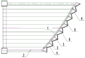
Fig. 1 is a schematic structural view of a support device for a zigzag floor structure according to the present invention.
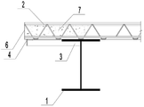
Fig. 2 is a schematic view of the salient point support of the sawtooth structure of the supporting device for the sawtooth floor structure of the present invention.
Fig. 3 is a schematic view of the supporting of the concave points of the zigzag floor structure of the supporting device for a zigzag floor structure according to the present invention.
Fig. 4 is a schematic view of supporting points of the supporting device for a zigzag floor structure of the present invention.
Reference numerals:
the steel bar truss floor slab comprises 1-steel beams, 2-steel bar truss floor slab plates, 3-plane overhanging pieces, 4-first edge sealing pieces, 5-inclined supports, 6-second edge sealing pieces, 7-concrete, 8-connecting bolts and 9-connecting lug plates.
Detailed Description
The technical solution in the embodiments of the present invention will be clearly and completely described below with reference to the accompanying drawings in the embodiments of the present invention.
Example 1
As shown in fig. 1 to 4, the present invention provides a supporting device for a zigzag floor structure, comprising: girder steel 1, plane cantilever 3, bearing diagonal 5 and banding piece. One end of the plane overhanging piece 3 is fixed on the steel beam 1, and the other end is connected with the edge sealing piece. The zigzag floor is arranged above the steel beam 1, and the lower bottom surface of the zigzag floor is attached to the plane cantilever piece 3. The edge sealing piece is arranged on the outer side of the saw teeth of the sawtooth-shaped floor slab, and the structure of the edge sealing piece is matched with that of the saw teeth. The bearing diagonal 5 sets up in the below of sawtooth bump, and the one end of bearing diagonal 5 is encorbelmented 3 with the plane and is connected, and the other end is connected with girder steel 1. The strength of the floor slab structure is enhanced by the inclined support 5 below the sawtooth convex points, and later-stage decoration is guaranteed. The edge sealing piece structure is matched with the structure of the sawteeth, so that the laying of the sawteeth floor slab is facilitated, the construction is simple and convenient, and the labor and the time are saved.
In a preferred embodiment, the edge banding comprises: a first edge seal member 4 and a second edge seal member 6 connected to each other. Wherein first banding piece 4 is encorbelmented 3 with the plane and is connected, and second banding piece 6 sets up in the outside of sawtooth, and the structure phase-match of 6 structures of second banding piece and sawtooth.
In a preferred embodiment, the zigzag floor comprises: the steel bar truss floor support plate 2 and the concrete 7; concrete 7 is poured into the steel bar truss floor support plate 2.
In a preferred embodiment, the steel beam 1 is provided with a connecting lug plate 9, and the inclined strut 5 is connected with the steel beam 1 through the connecting lug plate 9.
In a preferred embodiment, the supporting device for the zigzag floor slab structure further comprises connecting bolts 8, bolt holes are formed in the plane overhanging piece 3, the two ends of the inclined support 5 and the connecting lug plate 9, the bolt holes are connected through the connecting bolts 8, and the two ends of the inclined support 5 are respectively connected with the plane overhanging piece 3 and the connecting lug plate 9. The inclined support 5 is detachably mounted and fixed on the plane cantilever part and the steel beam, so that resources are saved.
In a preferred embodiment, the steel beam 1 is an i-shaped structure, the zigzag floor slab is connected with the upper surface of the upper flange plate of the i-shaped structure, the planar overhanging piece 3 is connected with the lower surface of the upper flange plate of the i-shaped structure, and the connecting lug plate 9 is fixedly arranged on the upper surface of the lower flange plate of the i-shaped structure and connected with the web.
Example 2
The invention also provides a supporting method of the supporting device for the zigzag floor structure, which comprises the following steps: one end of the plane overhanging piece 3 is fixed on the steel beam 1, and the edge sealing piece is fixed at the other end of the plane overhanging piece 3 according to the sawtooth structure of the sawtooth-shaped floor slab. An inclined support 5 is fixed below the sawtooth salient points, one end of the inclined support 5 is connected with the plane overhanging piece 3, and the other end of the inclined support is connected with the steel beam 1. And a zigzag floor slab is laid above the steel beam 1 and is positioned on the inner side of the edge sealing piece, and the lower bottom surface of the zigzag floor slab is attached to the plane overhanging piece 3.
In a preferred embodiment, lay zigzag floor above girder steel 1, and zigzag floor is located the inboard of banding piece, and zigzag floor's lower bottom surface and plane cantilever 3 laminating, include the following step: laying a steel bar truss floor bearing plate 2 above the steel beam 1, wherein the steel bar truss floor bearing plate 2 is positioned on the inner side of the edge sealing piece, and the bottom surface of the steel bar truss floor bearing plate 2 is attached to the plane overhanging piece 3; and concrete 7 is poured in the steel bar truss floor bearing plate 2.
The above is only a preferred embodiment of the present invention, and is not intended to limit the present invention, and various modifications and changes will occur to those skilled in the art. Any modification, equivalent replacement, improvement or the like made within the spirit and principle of the present invention is included in the scope of the claims of the present invention filed as filed.
Claims (8)
1. A support device for a zigzag floor structure, comprising: the steel beam (1), the plane cantilever (3), the inclined support (5) and the edge sealing piece;
one end of the plane overhanging piece (3) is fixed on the steel beam (1), and the other end of the plane overhanging piece is connected with the edge sealing piece; the zigzag floor is arranged above the steel beam (1), and the lower bottom surface of the zigzag floor is attached to the plane cantilever piece (3); the edge sealing piece is arranged on the outer side of the saw teeth of the sawtooth-shaped floor slab, and the structure of the edge sealing piece is matched with that of the saw teeth;
the inclined support (5) is arranged below the sawtooth salient points, one end of the inclined support (5) is connected with the plane overhanging piece (3), and the other end of the inclined support is connected with the steel beam (1).
2. A support arrangement for a zigzag floor structure according to claim 1, wherein the edging comprises: a first edge sealing member (4) and a second edge sealing member (6) which are connected with each other; wherein the first edge sealing piece (4) is connected with the plane overhanging piece (3), and the second edge sealing piece (6) is arranged on the outer side of the sawtooth.
3. A support arrangement for a zigzag floor structure according to claim 1, wherein the zigzag floor includes: the steel bar truss floor deck (2) and concrete (7); and the concrete (7) is poured in the steel bar truss floor bearing plate (2).
4. A support arrangement for a zigzag floor structure according to claim 1, wherein the steel beam (1) is provided with connecting lugs (9), and the diagonal support (5) is connected to the steel beam (1) by the connecting lugs (9).
5. A support arrangement for a zigzag floor structure according to claim 4, characterized in that the support arrangement for a zigzag floor structure further comprises a connecting bolt (8), bolt holes are provided in the planar overhang (3), both ends of the diagonal brace (5) and the connecting lug plate (9), the bolt holes are connected by the connecting bolt (8), and both ends of the diagonal brace (5) are connected to the planar overhang (3) and the connecting lug plate (9), respectively.
6. The supporting device for a zigzag floor structure according to claim 4, wherein the steel beam (1) is an I-shaped structure, the zigzag floor is connected with the upper surface of the upper flange plate of the I-shaped structure, the plane cantilever (3) is connected with the lower surface of the upper flange plate of the I-shaped structure, and the connecting lug plate (9) is fixedly arranged on the upper surface of the lower flange plate of the I-shaped structure and is connected with the web.
7. A method of supporting a support means for a zigzag floor structure, comprising the steps of:
one end of a plane cantilever (3) is fixed on a steel beam (1), and an edge sealing piece is fixed at the other end of the plane cantilever (3) according to the sawtooth structure of a sawtooth-shaped floor slab;
an inclined support (5) is fixed below the sawtooth convex points, one end of the inclined support (5) is connected with the plane cantilever (3), and the other end of the inclined support is connected with the steel beam (1);
a zigzag floor slab is laid above the steel beam (1), the zigzag floor slab is located on the inner side of the edge sealing piece, and the lower bottom surface of the zigzag floor slab is attached to the plane overhanging piece (3).
8. The supporting method according to claim 7, wherein a zigzag floor is laid above the steel beam (1) and inside the edge banding, and the lower bottom surface of the zigzag floor is attached to the plane cantilever (3), comprising the steps of:
laying a steel bar truss floor bearing plate (2) above the steel beam (1), wherein the steel bar truss floor bearing plate (2) is positioned on the inner side of the edge sealing piece, and the bottom surface of the steel bar truss floor bearing plate (2) is attached to the plane overhanging piece (3);
and concrete (7) is poured in the steel bar truss floor bearing plate (2).
Priority Applications (1)
| Application Number | Priority Date | Filing Date | Title |
|---|---|---|---|
| CN202110266375.2A CN113136997A (en) | 2021-03-11 | 2021-03-11 | Supporting device and supporting method for zigzag floor structure |
Applications Claiming Priority (1)
| Application Number | Priority Date | Filing Date | Title |
|---|---|---|---|
| CN202110266375.2A CN113136997A (en) | 2021-03-11 | 2021-03-11 | Supporting device and supporting method for zigzag floor structure |
Publications (1)
| Publication Number | Publication Date |
|---|---|
| CN113136997A true CN113136997A (en) | 2021-07-20 |
Family
ID=76811039
Family Applications (1)
| Application Number | Title | Priority Date | Filing Date |
|---|---|---|---|
| CN202110266375.2A Withdrawn CN113136997A (en) | 2021-03-11 | 2021-03-11 | Supporting device and supporting method for zigzag floor structure |
Country Status (1)
| Country | Link |
|---|---|
| CN (1) | CN113136997A (en) |
Cited By (1)
| Publication number | Priority date | Publication date | Assignee | Title |
|---|---|---|---|---|
| CN114622713A (en) * | 2022-03-29 | 2022-06-14 | 东南大学 | Connecting assembly between floor boards supported by construction climbing frame and steel beam |
Citations (5)
| Publication number | Priority date | Publication date | Assignee | Title |
|---|---|---|---|---|
| GB381749A (en) * | 1931-11-14 | 1932-10-13 | Tom Pickles | Improvements in the construction of suspended concrete floors |
| CN208502236U (en) * | 2018-06-15 | 2019-02-15 | 桐乡中卓金属构件有限公司 | A kind of edge banding apparatus for concrete floor edge in steel construction |
| CN109594700A (en) * | 2018-12-13 | 2019-04-09 | 杭萧钢构股份有限公司 | A kind of included shearing-resistant member U-shaped steel combination beam |
| CN111188457A (en) * | 2020-01-07 | 2020-05-22 | 山东建筑大学 | Edge sealing beam structure of super high-rise steel structure building and construction method |
| CN214835056U (en) * | 2021-03-11 | 2021-11-23 | 中建一局集团建设发展有限公司 | Supporting device for bearing plate of sawtooth-shaped steel bar truss floor |
-
2021
- 2021-03-11 CN CN202110266375.2A patent/CN113136997A/en not_active Withdrawn
Patent Citations (5)
| Publication number | Priority date | Publication date | Assignee | Title |
|---|---|---|---|---|
| GB381749A (en) * | 1931-11-14 | 1932-10-13 | Tom Pickles | Improvements in the construction of suspended concrete floors |
| CN208502236U (en) * | 2018-06-15 | 2019-02-15 | 桐乡中卓金属构件有限公司 | A kind of edge banding apparatus for concrete floor edge in steel construction |
| CN109594700A (en) * | 2018-12-13 | 2019-04-09 | 杭萧钢构股份有限公司 | A kind of included shearing-resistant member U-shaped steel combination beam |
| CN111188457A (en) * | 2020-01-07 | 2020-05-22 | 山东建筑大学 | Edge sealing beam structure of super high-rise steel structure building and construction method |
| CN214835056U (en) * | 2021-03-11 | 2021-11-23 | 中建一局集团建设发展有限公司 | Supporting device for bearing plate of sawtooth-shaped steel bar truss floor |
Non-Patent Citations (1)
| Title |
|---|
| 张楠: "超高悬挑锯齿板斜支撑施工技术", 《建筑技术》 * |
Cited By (1)
| Publication number | Priority date | Publication date | Assignee | Title |
|---|---|---|---|---|
| CN114622713A (en) * | 2022-03-29 | 2022-06-14 | 东南大学 | Connecting assembly between floor boards supported by construction climbing frame and steel beam |
Similar Documents
| Publication | Publication Date | Title |
|---|---|---|
| CN105625186A (en) | Method for constructing large-section concrete Y-shaped column | |
| CN103352417B (en) | A kind of prestress concrete variable cross-section box girder bridge, Hanging Basket and construction method thereof | |
| CN114770706B (en) | Light T-beam prefabrication equipment and prefabrication installation construction method | |
| CN102605717A (en) | Pier-top longitudinal support scaffolding method | |
| CN103603494B (en) | A kind of ultra-thin steel truss sloping core construction method and formwork structure | |
| CN113136997A (en) | Supporting device and supporting method for zigzag floor structure | |
| CN113202185B (en) | Energy-saving building steel structure system and installation process thereof | |
| CN214835056U (en) | Supporting device for bearing plate of sawtooth-shaped steel bar truss floor | |
| CN211816942U (en) | Simple and easy erection joint reinforced structure of building steel construction | |
| CN209891551U (en) | Combined beam composed of steel beam and steel bar truss floor support plate | |
| CN209523198U (en) | A kind of underpinning structure supporting lattice column | |
| CN207919358U (en) | A kind of bottom web reinforcement binding positioning moulding bed | |
| CN215947924U (en) | Support bearing structure for pier stud bent cap | |
| CN210288825U (en) | Assembled and cast-in-situ combined beam plate structure | |
| CN210530084U (en) | Open type steel reinforced concrete composite truss floor | |
| CN211447283U (en) | Connecting beam of main building and skirt house | |
| CN114108499A (en) | Suspended casting beam reference section hinged type triangular bracket combined hanging basket integrated device and construction method thereof | |
| CN210976584U (en) | Combined type supporting template for constructional engineering | |
| CN209194354U (en) | High-altitude long-span binder base-supporting shellfish thunder support construction | |
| CN219411452U (en) | Anti-drop's superimposed sheet | |
| CN211769920U (en) | Foundation for roof tower crane installation | |
| CN217680517U (en) | Self-locking type cylindrical template | |
| CN215630966U (en) | Support-free reinforced concrete one-way beam assembly box | |
| CN213772978U (en) | Wet seam hanging die for prefabricated bent cap | |
| CN208533700U (en) | High-altitude overhanging shape steel support |
Legal Events
| Date | Code | Title | Description |
|---|---|---|---|
| PB01 | Publication | ||
| PB01 | Publication | ||
| SE01 | Entry into force of request for substantive examination | ||
| SE01 | Entry into force of request for substantive examination | ||
| WW01 | Invention patent application withdrawn after publication | ||
| WW01 | Invention patent application withdrawn after publication |
Application publication date: 20210720 |