CN113115477B - Data transmission method, terminal and computer readable storage medium - Google Patents
Data transmission method, terminal and computer readable storage medium Download PDFInfo
- Publication number
- CN113115477B CN113115477B CN202110407566.6A CN202110407566A CN113115477B CN 113115477 B CN113115477 B CN 113115477B CN 202110407566 A CN202110407566 A CN 202110407566A CN 113115477 B CN113115477 B CN 113115477B
- Authority
- CN
- China
- Prior art keywords
- terminal
- link
- channel
- configuration information
- base station
- Prior art date
- Legal status (The legal status is an assumption and is not a legal conclusion. Google has not performed a legal analysis and makes no representation as to the accuracy of the status listed.)
- Active
Links
Images


Classifications
-
- H—ELECTRICITY
- H04—ELECTRIC COMMUNICATION TECHNIQUE
- H04W—WIRELESS COMMUNICATION NETWORKS
- H04W76/00—Connection management
- H04W76/10—Connection setup
-
- H—ELECTRICITY
- H04—ELECTRIC COMMUNICATION TECHNIQUE
- H04L—TRANSMISSION OF DIGITAL INFORMATION, e.g. TELEGRAPHIC COMMUNICATION
- H04L5/00—Arrangements affording multiple use of the transmission path
- H04L5/003—Arrangements for allocating sub-channels of the transmission path
- H04L5/0053—Allocation of signaling, i.e. of overhead other than pilot signals
-
- Y—GENERAL TAGGING OF NEW TECHNOLOGICAL DEVELOPMENTS; GENERAL TAGGING OF CROSS-SECTIONAL TECHNOLOGIES SPANNING OVER SEVERAL SECTIONS OF THE IPC; TECHNICAL SUBJECTS COVERED BY FORMER USPC CROSS-REFERENCE ART COLLECTIONS [XRACs] AND DIGESTS
- Y02—TECHNOLOGIES OR APPLICATIONS FOR MITIGATION OR ADAPTATION AGAINST CLIMATE CHANGE
- Y02D—CLIMATE CHANGE MITIGATION TECHNOLOGIES IN INFORMATION AND COMMUNICATION TECHNOLOGIES [ICT], I.E. INFORMATION AND COMMUNICATION TECHNOLOGIES AIMING AT THE REDUCTION OF THEIR OWN ENERGY USE
- Y02D30/00—Reducing energy consumption in communication networks
- Y02D30/70—Reducing energy consumption in communication networks in wireless communication networks
Abstract
A data transmission method, a terminal and a computer readable storage medium are provided. The method comprises the following steps: and when the first terminal is not connected with the base station through the uu link and the second terminal is connected with the base station through the uu link, the first terminal performs data transmission on the side link between the first terminal and the second terminal based on the transmission parameter configuration information sent by the base station through the uu link between the first terminal and the second terminal. By applying the scheme, data transmission on the side link can be realized.
Description
Technical Field
The present invention relates to the field of communications technologies, and in particular, to a data transmission method, a terminal, and a computer-readable storage medium.
Background
In a wireless communication system, a uu link is a wireless communication protocol between a User Equipment (UE) and a base station (UTRAN), where the base station may be a Long Term Evolution (LTE) base station (eNB), a New Radio base station (gNB) for fifth generation mobile communication (5G), and a base station in other network systems. Side link (sidelink) refers to a wireless communication protocol between a UE and a UE without participation of a base station.
In an actual communication process, if data transmission on the uu link and the side link is to be achieved, a sending end and a receiving end need to first obtain transmission configuration parameters sent by a base station, and receive or send data based on the transmission configuration parameters.
At present, an LTE system sends transmission configuration parameters in a broadcast manner, and does not support transmission parameter configuration on uu links and sidelink. The 5G NR system only supports transmission parameter configuration on the uu link, so that only data transmission on the uu link can be realized.
Therefore, how to configure transmission parameters on the side link to realize data transmission on the side link becomes an urgent problem to be solved.
Disclosure of Invention
The problem to be solved by the invention is how to realize data transmission on the side link.
In order to solve the above problem, an embodiment of the present invention provides a data transmission method, where the method includes: and when the first terminal is not connected with the base station through the uu link and the second terminal is connected with the base station through the uu link, the first terminal performs data transmission on the side link between the first terminal and the second terminal based on the transmission parameter configuration information sent by the base station through the uu link between the first terminal and the second terminal.
Optionally, the method further comprises: when a uu link is connected between a first terminal and a base station, the first terminal performs data transmission on a side link between the first terminal and a second terminal based on transmission parameter configuration information sent by the base station through the uu link.
Optionally, the transmission parameter configuration information includes at least one of: sending configuration information; configuration information is received.
Optionally, the receiving the configuration information includes: transmitting configuration indication status information, wherein the sending of the configuration indication status information comprises: 1 or 2 quasi co-located QCL information.
Optionally, the QCL information includes: identification information of 1 reference signal or channel, and QCL type information corresponding to the reference signal or channel.
Optionally, the performing, by the first terminal, data transmission on the side link between the first terminal and the second terminal based on the transmission parameter configuration information sent by the base station through the uu link includes: and the first terminal receives the corresponding reference signal or channel based on the QCL type and the reference signal or channel indicated by the corresponding QCL information, or configures the corresponding reference signal or channel to have the same receiving parameters as the QCL type and the reference signal or channel indicated by the corresponding QCL information.
Optionally, the reference signal or channel in the QCL information includes any one of: an edge link synchronization signal; a physical edge link broadcast channel; a side link synchronization signal and a physical side link broadcast channel; physical side link discovery channels; a side link feedback channel; side link channel sounding reference signals; a side link channel state indication reference signal; uu link synchronization signal and physical side link broadcast channel; a uu link channel sounding reference signal; uu link channel status indication reference signals; the uu link tracks the reference signal.
Optionally, the sending the configuration information includes: identification information of a reference signal or channel for indicating transmission parameters.
Optionally, the performing, by the first terminal, data transmission on the side link between the first terminal and the second terminal based on the transmission parameter configuration information sent by the base station through the uu link includes: and the first terminal transmits the corresponding reference signal or channel by adopting the same transmission parameter as the reference signal or channel indicated in the transmission parameter configuration information.
Optionally, the first terminal obtains, from a preset mapping table, a transmission parameter corresponding to a reference signal or a channel indicated in the transmission configuration information.
Optionally, the reference signal or channel for indicating the transmission parameter includes any one of: an edge link synchronization signal; a side link synchronization signal and a physical side link broadcast channel; side link channel sounding reference signals; a side link channel state indication reference signal; a set of edge link control resources; physical side link discovery channels; a physical edge link broadcast channel; a side link feedback channel; uu link synchronization signals and physical broadcast channels; a uu link channel sounding reference signal; uu link tracking reference signals; uu link channel status indication reference signals; a physical uplink shared channel; uu link physical uplink control channel.
Optionally, when the first terminal is a transmitting end, the method further includes: the first terminal receives beam scanning indication information sent by a base station through a uu link, wherein the beam scanning indication information is used for indicating a beam scanning direction; and the first terminal determines the beam used on the side link between the first terminal and the second terminal based on the beam scanning indication information and the transmission parameter configuration information, and performs data transmission.
Optionally, the method further comprises: and when the first terminal and the second terminal are not connected with the base station through the uu link, the first terminal performs data transmission on the side link between the first terminal and the second terminal based on the transmission parameter configuration information sent by a transmitting terminal, wherein the transmitting terminal is the first terminal or the second terminal.
An embodiment of the present invention further provides a terminal, where the terminal includes: a first beam obtaining unit, adapted to obtain, when there is no uu link connection between the first terminal and a base station and there is uu link connection between a second terminal and the base station, transmission parameter configuration information sent by the base station through the uu link connection with the second terminal; and the data transmission unit is suitable for carrying out data transmission on the side link between the first terminal and the second terminal based on the transmission parameter configuration information.
Optionally, the terminal further includes: and the second beam acquisition unit is suitable for acquiring the transmission parameter configuration information sent by the base station through the uu link when the uu link is connected between the first terminal and the base station.
Optionally, the transmission parameter configuration information includes at least one of: sending configuration information; configuration information is received.
Optionally, the receiving the configuration information includes: transmitting configuration indication status information, wherein the sending of the configuration indication status information comprises: 1 or 2 quasi co-located QCL information.
Optionally, the QCL information includes: identification information of 1 reference signal or channel, and QCL type information corresponding to the reference signal or channel.
Optionally, the data transmission unit is adapted to receive the corresponding reference signal or channel based on the QCL type and the reference signal or channel indicated by the corresponding QCL information, or configure the corresponding reference signal or channel to have the same reception parameters as the QCL type and the reference signal or channel indicated in the corresponding QCL information.
Optionally, the reference signal or channel in the QCL information includes any one of: an edge link synchronization signal; a physical edge link broadcast channel; a side link synchronization signal and a physical side link broadcast channel; physical side link discovery channels; a side link feedback channel; side link channel sounding reference signals; a side link channel state indication reference signal; uu link synchronization signal and physical side link broadcast channel; a uu link channel sounding reference signal; uu link channel status indication reference signals; the uu link tracks the reference signal.
Optionally, the sending the configuration information includes: identification information of a reference signal or channel for indicating transmission parameters.
Optionally, the data transmission unit is adapted to transmit the corresponding reference signal or channel by using the same transmission parameter as the reference signal or channel indicated in the transmission parameter configuration information.
Optionally, the transmission parameters corresponding to the reference signal or the channel indicated in the transmission configuration information are obtained from a preset mapping table.
Optionally, the reference signal or channel for indicating the transmission parameter includes any one of the following: an edge link synchronization signal; a side link synchronization signal and a physical side link broadcast channel; side link channel sounding reference signals; a side link channel state indication reference signal; a set of edge link control resources; physical side link discovery channels; a physical edge link broadcast channel; a side link feedback channel; uu link synchronization signals and physical broadcast channels; a uu link channel sounding reference signal; uu link tracking reference signals; uu link channel status indication reference signals; a physical uplink shared channel; uu link physical uplink control channel.
Optionally, the terminal further includes: a receiving unit, adapted to receive, when the first terminal is a transmitting end, beam scanning indication information sent by a base station through a uu link, where the beam scanning indication information is used to indicate a beam scanning direction; and the data transmission unit is adapted to determine a beam used on a side link between the first terminal and the second terminal based on the beam scanning indication information and the transmission parameter configuration information, and perform data transmission.
Optionally, the terminal further includes: and a third beam obtaining unit, adapted to obtain, when there is no uu link connection between the base station and each of the first and second terminals, transmission parameter configuration information sent by a transmitting end, and perform data transmission on a side link between the first and second terminals, where the transmitting end is the first terminal or the second terminal.
Embodiments of the present invention further provide a computer-readable storage medium, on which computer instructions are stored, and when the computer instructions are executed, the method of any one of the above-mentioned steps is performed.
The embodiment of the present invention further provides a user terminal, which includes a memory and a processor, where the memory stores computer instructions capable of running on the processor, and the processor executes any of the steps of the method when executing the computer instructions.
Compared with the prior art, the technical scheme of the embodiment of the invention has the following advantages:
by adopting the scheme, when the first terminal is not connected with the base station through the uu link and the second terminal is connected with the base station through the uu link, the first terminal realizes data transmission on the side link between the first terminal and the second terminal based on the transmission parameter configuration information sent by the base station through the uu link between the first terminal and the second terminal.
Drawings
FIG. 1 is a flow chart of a data transmission method in an embodiment of the invention;
fig. 2 to 4 are schematic diagrams of connections between a UE and a base station according to an embodiment of the present invention;
fig. 5 is a schematic diagram of repeated beam scanning between a UE and a base station;
fig. 6 is a schematic structural diagram of a terminal in an embodiment of the present invention.
Detailed Description
Currently, the 5G NR system only provides a scheme in which a terminal configures transmission parameters on a uu link (uulink), and may be introduced on a sidelink (sidelink) of NR V2X (Vehicle to X, i.e., Vehicle-to-outside information exchange) in the future.
To this end, an embodiment of the present invention provides a data transmission method, where when there is no uu link connection between a first terminal and a base station and there is a uu link connection between a second terminal and the base station, the first terminal implements data transmission on a side link between the first terminal and the second terminal based on transmission parameter configuration information sent by the base station through the uu link between the first terminal and the second terminal.
In order to make the aforementioned objects, features and advantages of the present invention comprehensible, embodiments accompanied with figures are described in detail below.
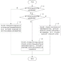
Referring to fig. 1, an embodiment of the present invention provides a data transmission method, where the method may include the following steps:
and step 11, judging whether a uu link is connected between the first terminal and the base station.
In an implementation, the first terminal may be connected to the base station through a uu interface, and in this case, there is a uu link connection between the first terminal and the base station. The first terminal and the base station may not be connected through the uu interface, and at this time, there is no uu link connection between the first terminal and the base station.
In a specific implementation, whether the first terminal has uu link connection with the base station may be determined by determining whether the first terminal belongs to a UE in a coverage area of the base station. When the first terminal belongs to a UE (i.e., an in-coverage UE) within the coverage of the base station, it may be determined that the first terminal has uu link connection with the base station. And when the first terminal belongs to the UE (out-of-coverage UE) out of the coverage range of the base station, judging that the first terminal is not connected with the uu link of the base station.
And executing step 12 when the uu link is connected between the first terminal and the base station, otherwise, executing step 13.
And step 12, the first terminal performs data transmission on the side link between the first terminal and the second terminal based on the transmission parameter configuration information sent by the base station through the uu link.
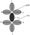
For example, referring to fig. 2-4, a sidelink is formed between UE-a and UE-B. The type of the side link may be a PC5link, or other types of links. The uu link formed between the UE-A and the base station gNB is uulink 1, and the uu link formed between the UE-B and the base station gNB is uulink 2.
As shown in fig. 2, when UE-a is used as the first terminal, the base station gNB may send the transmission parameter configuration information to UE-a through a uu link 1. And the UE-A performs data transmission on the sidelink according to the transmission parameter configuration information.
As shown in fig. 3, since UE-a and UE-B both have uu links with the base station gNB, the base station gNB may send transmission parameter configuration information to UE-a through uu link1, or send transmission parameter configuration information to UE-B based on uu link 2. Accordingly, UE-B and UE-a may perform data transmission on the sidelink based on the transmission parameter configuration information.
In a specific implementation, the transmission parameter configuration information may only include the transmission or reception configuration information, or may include both the transmission and reception configuration information.
For example, referring to fig. 3, when UE-a is a transmitting end and UE-B is a receiving end, the configuration information sent by base station gNB to UE-a via uulink 1 may only include transmit configuration information, so that UE-a may determine a transmit beam used on the side link, a spatial configuration (spatial configuration), a spatial filter configuration (spatial Tx parameter), a spatial transmit parameter (spatial Tx parameter), and the like based on the transmit configuration information. The base station gNB sends the reception configuration information to the UE-B through uulink 2, so that the UE-B can determine Quasi co-location (QCL) information used on the sidelink based on the reception configuration information.
Referring to fig. 2, the configuration information sent by the base station gNB to the UE-a through uulink 1 may include both sending and receiving configuration information, and after receiving the configuration information, the UE-a determines parameters such as a transmit beam used on the side link, spatial configuration (spatial configuration), spatial filter configuration (spatial filter configuration), and spatial sending parameter (spatial Tx parameter), based on the sending configuration information, and forwards the receiving configuration information to the UE-B. UE-B may determine QCL information for use on the side link based on the received configuration information.
And step 13, judging whether a uu link is connected between the second terminal and the base station.
In a specific implementation, when there is no uu link connection between the first terminal and the base station, it is first determined whether there is a uu link connection between the second terminal and the base station.
In a specific implementation, whether the second terminal has uu link connection with the base station may be determined by determining whether the second terminal belongs to the UE within the coverage of the base station. When the second terminal belongs to a UE (i.e., an in-coverage UE) within the coverage of the base station, it may be determined that the second terminal has uu link connection with the base station. And when the second terminal belongs to the UE (out-of-coverage UE) out of the coverage of the base station, judging that the second terminal has no uu link connection with the base station.
And when the second terminal is connected with the base station by the uu link, executing step 14, otherwise, executing step 15.
And step 14, the first terminal performs data transmission on the side link between the first terminal and the second terminal based on the transmission parameter configuration information sent by the base station through the uu link between the first terminal and the second terminal.
As shown in fig. 2, UE-B is used as the first terminal, UE-a is used as the second terminal, UE-B and the base station gNB have no uu link connection, but UE-a and the base station gNB have uu link connection. At this time, the base station gNB may send the sending configuration information to the UE-a through uulink 1, and then the UE-a sends the receiving configuration information to the UE-B, thereby implementing management of beams and other receiving parameters used on the sidelink between the UE-B and the UE-a.
And step 15, the first terminal performs data transmission on a side link between the first terminal and a second terminal based on the transmission parameter configuration information sent by a transmitting terminal, wherein the transmitting terminal is the first terminal or the second terminal.
Referring to fig. 4, in an implementation, UE-a may serve as a transmitting end and UE-B as a receiving end, or UE-a may serve as a receiving end and UE-B as a transmitting end.
When no uu link is connected between UE-A and UE-B and base station gNB, the UE as the transmitting end determines the transmission parameters used on the side link.
The following describes the contents of the sending configuration information and the receiving configuration information in detail with reference to fig. 2 to 4, respectively:
in a specific implementation, the receiving configuration information may indicate the receiving configuration information corresponding to the corresponding reference signal or channel in various ways.
In an embodiment of the present invention, the receiving Configuration information may include Transmission Configuration Indication (TCI) state information, i.e., TCI-state information. The TCI-state information may include information for 1 or 2 QCLs.
In a specific implementation, the transmission parameter configuration Information may be carried by side link Control Information (SCI), Downlink Control Information (DCI), Media Access Control-user edge (MAC-CE), or higher layer signaling (e.g., radio resource Control RRC).
Specifically, the transmission and reception configuration information sent by the base station gNB to the UE through uulink may be carried by DCI, MAC-CE, or higher layer signaling. The receiving configuration information sent by the UE serving as the transmitting end on the side link to the UE serving as the receiving end on the side link may be carried by SCI, MAC-CE, or higher layer signaling.
In a specific implementation, the QCL information may include identification information of 1 Reference Signal (RS) or channel and QCL type information corresponding to the Reference Signal or channel, where the QCL type corresponding to the Reference Signal or channel may specifically include A, B, C and D, or a subset of set types { A, B, C, D }, and parameters corresponding to each type are different.
The type D (QCL-type) may indicate a Spatial Rx parameter (Spatial Rx parameter), so the QCL-type D may be used to indicate a receiving beam corresponding to a reference signal or a channel. Type a (QCL-TypeA) may indicate Doppler shift (Doppler shift), Doppler spread (Doppler spread), average delay (average delay), and delay spread (delay spread). Type B (QCL-TypeB) may indicate Doppler shift (Doppler shift) and Doppler spread (Doppler spread). The type C (QCL-TypeC) may indicate average delay (average delay) and delay spread (delay spread).
In a specific implementation, the reference signal or channel in the QCL information may be any one of: side Link Synchronization Signals (SLSS); physical Sidelink Broadcast Channel (PSBCH); side link synchronization signals and physical side link broadcast channels (SLSS + PSBCH, SL-SSB); physical Sidelink Discovery Channel (PSDCH); a side link feedback channel (SL-FC); a Sidelink Sounding Reference Signal (SL-SRS); a side link Channel State indication Reference signal (SL-CSI-RS); uu link synchronization signal and physical broadcast channel (SS + PBCH, SSB); uu link channel Sounding Reference Signals (SRS); uu link channel state indication reference signals (CSI-RS); the uu link tracks The Reference Signal (TRS).
In a specific implementation, the TCI-state information in the received configuration information may include two QCL information, where a QCL type corresponding to one QCL information may be type A, B or C, and a QCL type corresponding to the other QCL information is type D. When receiving the receiving configuration information, the first terminal may receive a corresponding reference signal or channel based on the QCL type indicated by the corresponding QCL information and the RS or channel corresponding to the QCL type, or the first terminal considers that the configured reference signal or channel has the same parameters as the QCL type indicated in the QCL information and the RS or channel corresponding to the QCL type. Alternatively, the TCI-state information in the received configuration information may include a type of QCL information, where the corresponding type of QCL may be type A, B or C.
The corresponding reference signals or channels, i.e. the reference signals or channels having the same parameter characteristics as the QCL type indicated in the corresponding QCL information and the corresponding RS or channels thereof, may be: physical side link shared Channel (PSSCH), Physical side link Control Channel (PSCCH), PSDCH, PSBCH, SL-SSB, Automatic Gain Control (AGC) training Signal, side link Channel State Information Reference Signal (SL-CSIRS), SLSS, SL-SRS, or SL-FC.
In a specific implementation, the UE may receive one or more of the PSCCH, PSDCH, PSBCH, AGC training signal, SLSS, SL-CSIRS, SL-SRS, and SL-FC based on the QCL information indicated by the TCI-state information, or may receive all of the reference signals or channels until the UE receives new TCI-state information. That is, before the UE receives new TCI-state information, a corresponding reference signal or channel is received according to the most recently received TCI-state information.
It is understood that the UE specifically receives which reference signal or channel based on the receiving configuration information indicated by the TCI-state information, and how to specifically indicate may be determined by other indication information, which does not limit the present invention, and all of them are within the protection scope of the present invention. For example, the receive beam indicated by the QCL-type may be indicated in the receive beam configuration information for receiving the pscch.
As another embodiment, the first terminal may configure one TCI-state information set through higher layer signaling, and then activate several TCI-states therein through the MAC-CE. And one of the TCI-state information is indicated by SCI. The activated TCI-state information may include QCL configuration information of one or more of PSSCH, PSCCH, SL-SRS, SL-FC, SL-CSI-RS, SLSS, PSDCH, PSBCH, SL-SSB, AGC training signal, SSB, SRS, TRS, CSI-RS, PUCCH, PUSCH. Wherein if the MAC-CE activates only one TCI-state, then SCI re-indication is not needed.
For example, the first terminal configures 64 TCI-states, activates 8 TCI-states through the MAC-CE, and specifically indicates which TCI-state is selected for use as QCL configuration information of one or more of PSSCH, PSCCH, SL-SRS, SL-FC, SL-CSI-RS, SLSS, PSDCH, PSBCH, SL-SSB, AGC training signal, SSB, SRS, TRS, CSI-RS, PUCCH, PUSCH through 3 bits of DCI.
In a specific implementation, the transmission configuration information may indicate the transmission parameters corresponding to the corresponding reference signals or channels in a plurality of ways, where the transmission parameters may include: receive beams, spatial configurations, spatial filtering configurations, or spatial transmit parameters.
Wherein, the transmission configuration information may be carried by DCI, MAC-CE, or higher layer signaling.
In an embodiment of the present invention, the sending configuration information may include: identification information of a reference signal or channel for indicating transmission parameters.
In a specific implementation, the transmission configuration information may include sequence number indications of 1 reference signal or channel. The reference signal or channel may be any one of: SLSS, SL-SSB, SL-SRS, SL-CSI-RS, Sidelink Control resource set (SL-CORESET), Physical Sidelink Discovery Channel (PSDCH), PSBCH, SL-FC, SSB, SRS, Tracking Reference Signal (TRS), CSI-RS, Physical Uplink Shared Channel (PUSCH), and Physical Uplink Control Channel (PUCCH).
After receiving the sending configuration information, the first terminal may send the corresponding reference signal or channel by using the same sending parameter as the reference signal or channel indicated in the sending configuration information.
In a specific implementation, the UE may transmit one or more of PSCCH, SL-SRS, SL-FC, SL-CSI-RS, SLSS, PSDCH, PSBCH, SL-SSB, AGC training signal, SSB, SRS, TRS, CSI-RS, PUCCH, and PUSCH based on the transmission parameters indicated in the transmission configuration information, or may transmit all of the above reference signals or channels until the UE receives new transmission configuration information. That is, before the UE receives new transmission configuration information, the corresponding reference signal or channel is transmitted according to the most recently received transmission configuration information.
As another embodiment, the base station may configure a set through higher layer signaling, where each element in the set corresponds to a transmission parameter, and then activate several elements thereof through the MAC-CE. And then one element is indicated by the DCI. The element may correspond to one or more transmission parameters of PSSCH, PSCCH, SL-SRS, SL-FC, SL-CSI-RS, SLSS, PSDCH, PSBCH, SL-SSB, AGC training signal, SSB, SRS, TRS, CSI-RS, PUCCH, PUSCH. Wherein if the MAC-CE activates only one element, DCI re-indication is not required at this time.
For example, the first terminal configures 64 transmission parameter (spatialrelalationinfo-state) sets, where each element in the transmission parameter set represents a transmission beam, a spatial configuration, a spatial filtering configuration, or a spatial transmission parameter. And then activating 8 transmission parameter sets through the MAC-CE, and specifically indicating which transmission parameter set is selected to be used as one or more than two transmission parameters of PSSCH, PSCCH, SL-SRS, SL-FC, SL-CSI-RS, SLSS, PSDCH, PSBCH, SL-SSB, AGC training signal, SSB, SRS, TRS, CSI-RS, PUCCH and PUSCH through 3 bits of DCI.
It is understood that the UE specifically transmits which reference signal or channel based on the transmission configuration information, and how to specifically indicate may be determined by other indication information, which does not limit the present invention and is within the protection scope of the present invention. For example, the transmit beam, spatial configuration, spatial filtering configuration, or spatial transmit parameter may be indicated in the transmit configuration information for receiving the SL-CSI-RS.
In an embodiment of the present invention, the reference signal or the channel and the corresponding transmission parameter may be stored in a preset mapping table. After receiving the sending configuration information, the first terminal may obtain, from a preset mapping table, a sending parameter corresponding to a reference signal or a channel indicated in the sending configuration information.
Specifically, a mapping table for a set { PSSCH, PSCCH, PUSCH, PUCCH, SRS, SL-CSI-RS, SL-SRS, PSDCH, SLSS, PSBCH, AGC training signal, SL-FC } or a subset thereof, and corresponding transmission configuration information may be established. Wherein the introduction of further channels or reference signals is not excluded.

TABLE 1
For example, referring to table 1, a mapping table between psch, PSCCH, SL-CSI-RS, and SL-SRS and corresponding transmission configuration information may be established. When the identification information indicated in the transmission configuration information is 1, the first terminal may determine, from table 1, that the transmission parameter used by the PSSCH is SpatialRelationInfo-11, the transmission parameter used by the PSCCH is SpatialRelationInfo-12, the transmission parameter used by the SL-CSI-RS is SpatialRelationInfo-13, and the transmission parameter used by the SL-SRS is spatialrelatedinfo-14.
The reference signal or channel and the corresponding transmission configuration information are stored in a mapping table manner, so that the first terminal can conveniently and quickly determine the transmission parameters corresponding to the reference signal or channel. In addition, since one identification information can indicate a plurality of reference signals or channels, bits occupied by the identification information of the reference signals or channels for sending configuration parameter management can be effectively saved.
It can be understood that, in a specific implementation, whether the base station indicates the transmission and reception configuration information on the side link through the uu link or the UE as the transmitting end determines the transmission and reception configuration information used on the side link, the implementation may refer to the above contents of the transmission and reception configuration information, and details are not described here.
In an embodiment of the present invention, when the first terminal is a transmitting end, the method may further include: the first terminal receives beam scanning indication information sent by a base station through a uu link, wherein the beam scanning indication information is used for indicating a beam scanning direction; and the first terminal determines the beam used on the side link between the first terminal and the second terminal based on the beam scanning indication information and the transmission parameter configuration information, and performs data transmission.
For example, referring to fig. 5, the base station gNB performs beam scanning in 1 to 4 directions. The UE should transmit or receive beams in four directions a to d after receiving the beam configuration information and determining the corresponding transmit beam or receive beam. However, since the direction 3 and the direction c are repeated directions, the base station gNB may transmit beam scanning indication information to the UE, and the UE may determine a beam used on the sidelink based on the beam scanning indication information and the beam configuration information, so as to reduce power consumption of the UE.
In particular implementations, the base station may indicate the beam scanning direction by way of a bitmap. For example, the base station may indicate SLSS via a bitmap, where bit 1 indicates that the UE uses the same transmit beam when transmitting on the sidelink as when transmitting the SLSS. Of course, the base station may also indicate 1 or several SSBs or CSI-RSs through a bitmap, where bit 1 indicates that the UE does not use the same transmission parameters when transmitting on the side link, or the base station indicates 1 or several SSBs or CSI-RSs, and bit 1 indicates that the UE can only use the same transmission parameters when transmitting on the side link. Wherein the bitmap is carried by DCI or MAC-CE or higher layer signaling.
For example, 1001 indicates that the transmission parameters of SSBs with indices of 0 and 3 cannot be used as the transmission parameters of side link transmission SLSS, SL-SSB, SRS, SL-SRS, or SL-CSIRS.
For example, 1001 indicates that the transmission parameters of the SSB with index 0 and index 3 can be used as the transmission parameters of the side link transmission SLSS S, SL-SSB, SRS, SL-SRS, or SL-CSIRS.
As can be seen from the above, in the data transmission method in the embodiment of the present invention, when the first terminal directly or indirectly has uu link connection with the base station, the transmission parameter configuration information is sent by the base station, and when the first terminal directly has no uu link connection with the base station, the transmitting end determines the beam, the spatial configuration, the spatial filtering configuration, or the spatial sending and receiving parameter used on the side link, so that management of the beam used on the side link can be implemented.
In order to make the present invention better understood and realized by those skilled in the art, the following detailed description is provided for a device and a computer readable storage medium corresponding to the above method.
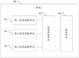
Referring to fig. 6, an embodiment of the present invention provides a terminal 60, where the terminal 60 may include: a first beam acquisition unit 61 and a beam determination unit 62. Wherein:
the first beam obtaining unit 61 is adapted to obtain, when there is no uu link connection between the first terminal and the base station and there is uu link connection between the second terminal and the base station, transmission parameter configuration information sent by the base station through the uu link connection between the base station and the second terminal;
the beam determining unit 62 is adapted to perform data transmission on the side link between the first terminal and the second terminal based on the transmission parameter configuration information.
In an embodiment of the present invention, the terminal 60 may further include: a second beam acquisition unit 63. Wherein:
the second beam obtaining unit 63 is adapted to obtain the transmission parameter configuration information sent by the base station through the uu link when the uu link is connected between the first terminal and the base station.
In an embodiment of the present invention, the transmission parameter configuration information may include at least one of the following:
sending configuration information;
configuration information is received.
In an embodiment of the present invention, the receiving configuration information may include: transmitting configuration indication status information, wherein the sending of the configuration indication status information comprises: 1 or 2 quasi co-located QCL information.
In an embodiment of the present invention, the QCL information includes: identification information of 1 reference signal or channel, and QCL type information corresponding to the reference signal or channel.
In an embodiment of the present invention, the first beam obtaining unit 61 is adapted to receive a corresponding reference signal or channel by using the receiving beam indicated by the receiving beam indication information.
In an embodiment of the present invention, the data transmission unit is adapted to receive the corresponding reference signal or channel based on the QCL type and the reference signal or channel indicated by the corresponding QCL information, or configure the corresponding reference signal or channel to have the same receiving parameters as the QCL type and the reference signal or channel indicated in the corresponding QCL information.
In an embodiment of the present invention, the reference signal or channel in the QCL information includes any one of: an edge link synchronization signal; a physical edge link broadcast channel; a side link synchronization signal and a physical side link broadcast channel; physical side link discovery channels; a side link feedback channel; side link channel sounding reference signals; a side link channel state indication reference signal; uu link synchronization signal and physical side link broadcast channel; a uu link channel sounding reference signal; uu link channel status indication reference signals; the uu link tracks the reference signal.
In an embodiment of the present invention, the sending configuration information includes: identification information of a reference signal or channel for indicating transmission parameters.
In an embodiment of the present invention, the data transmission unit is adapted to transmit the corresponding reference signal or channel by using the same transmission parameter as the reference signal or channel indicated in the transmission parameter configuration information.
In an embodiment of the present invention, the transmission parameters corresponding to the reference signal or the channel indicated in the transmission configuration information are obtained from a preset mapping table.
In an embodiment of the present invention, the reference signal or channel for indicating the transmission parameter may include any one of the following: an edge link synchronization signal; a side link synchronization signal and a physical side link broadcast channel; side link channel sounding reference signals; a side link channel state indication reference signal; a set of edge link control resources; a physical edge link discovery channel; a physical edge link broadcast channel; a side link feedback channel; uu link synchronization signals and physical broadcast channels; a uu link channel sounding reference signal; uu link tracking reference signals; uu link channel status indication reference signals; a physical uplink shared channel; uu link physical uplink control channel.
In an embodiment of the present invention, the terminal 60 may further include: a receiving unit 64. Wherein:
the receiving unit 64 is adapted to receive, when the first terminal is a transmitting end, beam scanning indication information sent by a base station through a uu link, where the beam scanning indication information is used for indicating a beam scanning direction;
the beam determining unit 62, the data transmitting unit, is adapted to determine a beam used on a side link between the first terminal and the second terminal based on the beam scanning indication information and the transmission parameter configuration information, and perform data transmission.
In an embodiment of the present invention, the terminal 60 may further include: the third beam obtaining unit 65 is adapted to obtain the transmission parameter configuration information sent by the transmitting end when there is no uu link connection between the base station and each of the first terminal and the second terminal, and perform data transmission on the side link between the first terminal and the second terminal, where the transmitting end is the first terminal or the second terminal.
The embodiment of the present invention further provides another computer-readable storage medium, where a computer instruction is stored, and when the computer instruction runs, the step of any one of the above-mentioned management methods for sending and receiving configuration information is executed, which is not described again.
In particular implementations, the computer-readable storage medium may include: ROM, RAM, magnetic or optical disks, and the like.
The embodiment of the present invention further provides a terminal, where the user terminal may include a memory and a processor, where the memory stores a computer instruction capable of being executed on the processor, and when the processor executes the computer instruction, the step of executing any of the data transmission methods in the foregoing embodiments is performed, and details are not repeated.
It is understood that the device (virtual device) containing the above functional units may be, for example: a chip, or a chip module, etc., without specific limitation.
Each module/unit included in each apparatus and product described in the above embodiments may be a software module/unit, or may also be a hardware module/unit, or may also be a part of a software module/unit and a part of a hardware module/unit. For example, for each device or product applied to or integrated into a chip, each module/unit included in the device or product may be implemented by hardware such as a circuit, or at least a part of the module/unit may be implemented by a software program running on a processor integrated within the chip, and the rest (if any) part of the module/unit may be implemented by hardware such as a circuit; for each device or product applied to or integrated with the chip module, each module/unit included in the device or product may be implemented by using hardware such as a circuit, and different modules/units may be located in the same component (e.g., a chip, a circuit module, etc.) or different components of the chip module, or at least some of the modules/units may be implemented by using a software program running on a processor integrated within the chip module, and the rest (if any) of the modules/units may be implemented by using hardware such as a circuit; for each device and product applied to or integrated in the terminal, each module/unit included in the device and product may be implemented by using hardware such as a circuit, and different modules/units may be located in the same component (e.g., a chip, a circuit module, etc.) or different components in the terminal, or at least part of the modules/units may be implemented by using a software program running on a processor integrated in the terminal, and the rest (if any) part of the modules/units may be implemented by using hardware such as a circuit.
Although the present invention is disclosed above, the present invention is not limited thereto. Various changes and modifications may be effected therein by one skilled in the art without departing from the spirit and scope of the invention as defined in the appended claims.
Claims (12)
1. A method of data transmission, comprising:
when a uu link does not exist between a first terminal and a base station and a uu link exists between a second terminal and the base station, the first terminal performs data transmission on a side link between the first terminal and the second terminal based on transmission parameter configuration information sent by the base station through the uu link between the first terminal and the second terminal;
the transmission parameter configuration information comprises sending configuration information; the sending configuration information includes: identification information of a reference signal or channel for indicating transmission parameters;
the first terminal performs data transmission on the sidelink between the first terminal and the second terminal based on the transmission parameter configuration information sent by the base station through the uu link, and includes: and the first terminal transmits the corresponding reference signal or channel by adopting the same transmission parameter as the reference signal or channel indicated in the transmission parameter configuration information.
2. The data transmission method of claim 1, further comprising:
when a uu link is connected between a first terminal and a base station, the first terminal performs data transmission on a side link between the first terminal and a second terminal based on transmission parameter configuration information sent by the base station through the uu link.
3. The data transmission method according to claim 1, wherein the first terminal obtains the transmission parameters corresponding to the reference signals or the channels indicated in the transmission configuration information from a preset mapping table.
4. The data transmission method of claim 1, wherein the reference signal or channel for indicating the transmission parameter comprises any one of:
an edge link synchronization signal;
a side link synchronization signal and a physical side link broadcast channel;
side link channel sounding reference signals;
a side link channel state indication reference signal;
a set of edge link control resources;
physical side link discovery channels;
a physical edge link broadcast channel;
a side link feedback channel;
uu link synchronization signals and physical broadcast channels;
a uu link channel sounding reference signal;
uu link tracking reference signals;
uu link channel status indication reference signals;
a physical uplink shared channel;
uu link physical uplink control channel.
5. The data transmission method of claim 1, further comprising:
and when the first terminal and the second terminal are not connected with the base station through the uu link, the first terminal performs data transmission on the side link between the first terminal and the second terminal based on the transmission parameter configuration information sent by a transmitting terminal, wherein the transmitting terminal is the first terminal or the second terminal.
6. A terminal, comprising:
the first beam obtaining unit is suitable for obtaining transmission parameter configuration information sent by a base station through a uu link between the base station and a second terminal when the first terminal is not connected with the base station through the uu link and the second terminal is connected with the base station through the uu link;
a data transmission unit, adapted to perform data transmission on a side link between the first terminal and the second terminal based on transmission parameter configuration information;
the transmission parameter configuration information comprises sending configuration information; the sending configuration information includes: identification information of a reference signal or channel for indicating transmission parameters;
the data transmission unit is adapted to transmit the corresponding reference signal or channel by using the same transmission parameter as the reference signal or channel indicated in the transmission parameter configuration information.
7. The terminal of claim 6, further comprising:
and the second beam acquisition unit is suitable for acquiring the transmission parameter configuration information sent by the base station through the uu link when the uu link is connected between the first terminal and the base station.
8. The terminal of claim 6, wherein the transmission parameters corresponding to the reference signals or the channels indicated in the transmission configuration information are obtained from a preset mapping table.
9. The terminal of claim 6, wherein the reference signal or channel for indicating the transmission parameter comprises any one of:
an edge link synchronization signal;
a side link synchronization signal and a physical side link broadcast channel;
side link channel sounding reference signals;
a side link channel state indication reference signal;
a set of edge link control resources;
physical side link discovery channels;
a physical edge link broadcast channel;
a side link feedback channel;
uu link synchronization signals and physical broadcast channels;
a uu link channel sounding reference signal;
uu link tracking reference signals;
uu link channel status indication reference signals;
a physical uplink shared channel;
uu link physical uplink control channel.
10. The terminal of claim 6, further comprising: and a third beam obtaining unit, adapted to obtain, when there is no uu link connection between the base station and each of the first and second terminals, transmission parameter configuration information sent by a transmitting end, and perform data transmission on a side link between the first and second terminals, where the transmitting end is the first terminal or the second terminal.
11. A computer readable storage medium having computer instructions stored thereon, which when executed on a processor perform the steps of the method of any one of claims 1 to 5.
12. A terminal comprising a memory and a processor, the memory having stored thereon computer instructions executable on the processor, wherein the processor, when executing the computer instructions, performs the steps of the method of any one of claims 1 to 5.
Priority Applications (1)
| Application Number | Priority Date | Filing Date | Title |
|---|---|---|---|
| CN202110407566.6A CN113115477B (en) | 2018-09-21 | 2018-09-21 | Data transmission method, terminal and computer readable storage medium |
Applications Claiming Priority (2)
| Application Number | Priority Date | Filing Date | Title |
|---|---|---|---|
| CN202110407566.6A CN113115477B (en) | 2018-09-21 | 2018-09-21 | Data transmission method, terminal and computer readable storage medium |
| CN201811107937.3A CN110944405B (en) | 2018-09-21 | 2018-09-21 | Data transmission method, terminal and computer readable storage medium |
Related Parent Applications (1)
| Application Number | Title | Priority Date | Filing Date |
|---|---|---|---|
| CN201811107937.3A Division CN110944405B (en) | 2018-09-21 | 2018-09-21 | Data transmission method, terminal and computer readable storage medium |
Publications (2)
| Publication Number | Publication Date |
|---|---|
| CN113115477A CN113115477A (en) | 2021-07-13 |
| CN113115477B true CN113115477B (en) | 2022-09-27 |
Family
ID=69905339
Family Applications (3)
| Application Number | Title | Priority Date | Filing Date |
|---|---|---|---|
| CN201811107937.3A Active CN110944405B (en) | 2018-09-21 | 2018-09-21 | Data transmission method, terminal and computer readable storage medium |
| CN202110407550.5A Active CN113115476B (en) | 2018-09-21 | 2018-09-21 | Data transmission method, terminal and computer readable storage medium |
| CN202110407566.6A Active CN113115477B (en) | 2018-09-21 | 2018-09-21 | Data transmission method, terminal and computer readable storage medium |
Family Applications Before (2)
| Application Number | Title | Priority Date | Filing Date |
|---|---|---|---|
| CN201811107937.3A Active CN110944405B (en) | 2018-09-21 | 2018-09-21 | Data transmission method, terminal and computer readable storage medium |
| CN202110407550.5A Active CN113115476B (en) | 2018-09-21 | 2018-09-21 | Data transmission method, terminal and computer readable storage medium |
Country Status (1)
| Country | Link |
|---|---|
| CN (3) | CN110944405B (en) |
Families Citing this family (4)
| Publication number | Priority date | Publication date | Assignee | Title |
|---|---|---|---|---|
| US20210184809A1 (en) * | 2019-12-13 | 2021-06-17 | Qualcomm Incorporated | Downlink control information based beam and pathloss reference signal configuration activation |
| US20210329604A1 (en) * | 2020-04-20 | 2021-10-21 | Mediatek Singapore Pte. Ltd. | Physical Layer Enhancements for Sidelink Communication |
| WO2021212459A1 (en) * | 2020-04-24 | 2021-10-28 | Mediatek Singapore Pte. Ltd. | Physical layer enhancements for sl communication |
| CN117279091A (en) * | 2022-06-14 | 2023-12-22 | 维沃移动通信有限公司 | Beam indication method, device and terminal |
Family Cites Families (11)
| Publication number | Priority date | Publication date | Assignee | Title |
|---|---|---|---|---|
| EP2560448A1 (en) * | 2011-08-18 | 2013-02-20 | Fujitsu Limited | Scheduling request enabled uplink transmission |
| CN102983944A (en) * | 2012-12-04 | 2013-03-20 | 中国联合网络通信集团有限公司 | Data transmission processing method, device and system |
| KR20160120250A (en) * | 2015-04-07 | 2016-10-17 | 삼성전자주식회사 | Method and apparatus for handover in a wireless communication system using beam forming |
| CN105357757B (en) * | 2015-09-25 | 2019-03-08 | 宇龙计算机通信科技(深圳)有限公司 | A kind of communication resource configuration method and device |
| US10257677B2 (en) * | 2015-10-16 | 2019-04-09 | Qualcomm Incorporated | System and method for device-to-device communication with evolved machine type communication |
| EP3223575B1 (en) * | 2015-11-19 | 2019-06-12 | ASUSTek Computer Inc. | Methods and apparatus for switching communication interface in a wireless communication system |
| CN106856611B (en) * | 2015-12-08 | 2021-08-10 | 中兴通讯股份有限公司 | Beam processing method, initial beam discovery method, base station and terminal |
| EP3255950A1 (en) * | 2016-06-06 | 2017-12-13 | ASUSTek Computer Inc. | Method and apparatus for resource allocation on d2d relay channel in a wireless communication system |
| CN107770781B (en) * | 2016-08-15 | 2021-08-27 | 华为技术有限公司 | D2D synchronization signal sending method and device |
| CN108419295B (en) * | 2017-02-10 | 2022-01-14 | 华为技术有限公司 | Method for communication between terminals, network side equipment and terminal |
| CN108541017B (en) * | 2017-03-02 | 2023-04-28 | 中兴通讯股份有限公司 | Method and device for configuring wireless resources |
-
2018
- 2018-09-21 CN CN201811107937.3A patent/CN110944405B/en active Active
- 2018-09-21 CN CN202110407550.5A patent/CN113115476B/en active Active
- 2018-09-21 CN CN202110407566.6A patent/CN113115477B/en active Active
Also Published As
| Publication number | Publication date |
|---|---|
| CN113115476A (en) | 2021-07-13 |
| CN110944405A (en) | 2020-03-31 |
| CN110944405B (en) | 2021-06-08 |
| CN113115477A (en) | 2021-07-13 |
| CN113115476B (en) | 2022-06-21 |
Similar Documents
| Publication | Publication Date | Title |
|---|---|---|
| CN113115477B (en) | Data transmission method, terminal and computer readable storage medium | |
| CN109964435B (en) | Method and communication device for transmitting reference signal | |
| EP3780461A1 (en) | Method and apparatus for transmitting and receiving uplink signal, storage medium, and electronic device | |
| CN110933749B (en) | Method and device for indicating beam | |
| CN111526587B (en) | Configuration method, device and equipment of side uplink resources | |
| CN110149714B (en) | Uplink transmission method, user equipment and network equipment | |
| CN111386741B (en) | Link recovery method, terminal equipment and network equipment | |
| US20170187428A1 (en) | CoMP JT COMMUNICATION METHOD AND BASE STATION | |
| CN110996395B (en) | Transmission configuration information indication method and device for auxiliary link, storage medium and terminal | |
| US20220264643A1 (en) | Method and apparatus for bwp switching indication on unlicensed spectrum | |
| US20230262824A1 (en) | Methods and apparatus to speed up direct acell activation | |
| CN112020143B (en) | State information sending and receiving method and device | |
| CN111726770A (en) | Communication method and device | |
| WO2023050402A1 (en) | Method and apparatus for beam determination | |
| US20210250949A1 (en) | Methods and Apparatus of Spatial Relation Switching in New Radio System | |
| CN110838861A (en) | Signal transmission method, beam determination method and device thereof | |
| EP3837773B1 (en) | Method and system for managing interference in multi trp systems | |
| WO2021227033A1 (en) | Control signaling for pucch reliability enhancement | |
| CN115941014A (en) | Transmission processing method, device and equipment | |
| US20230269810A1 (en) | Method for resource updating, electronic device, and storage medium | |
| WO2023056605A1 (en) | Method and apparatus for beam determination | |
| WO2024065558A1 (en) | Transmission configuration indication in wireless mobility | |
| CN116633479A (en) | Beam training method and communication device | |
| CN116367329A (en) | Beam determining method and device | |
| DE102022202051A1 (en) | Methods, devices and computer programs for wireless communication |
Legal Events
| Date | Code | Title | Description |
|---|---|---|---|
| PB01 | Publication | ||
| PB01 | Publication | ||
| SE01 | Entry into force of request for substantive examination | ||
| SE01 | Entry into force of request for substantive examination | ||
| GR01 | Patent grant | ||
| GR01 | Patent grant |