Disclosure of Invention
The invention aims to overcome the defects of the prior art and provides a mechanical dynamic movement structure of an electronic hand-manipulating timing belt.
In order to solve the technical problems, the invention adopts the following technical scheme:
an electronic hand-manipulating timing belt mechanical dynamic movement structure comprises a main clamping plate, a winding tooth mechanism, a hand-manipulating transmission mechanism and a mechanical dynamic mechanism, wherein the winding tooth mechanism, the hand-manipulating transmission mechanism and the mechanical dynamic mechanism are connected with the main clamping plate; the needle-manipulating transmission mechanism and the mechanical dynamic mechanism are also connected with the winding gear mechanism; the winding gear mechanism comprises a lower clamping plate, a vertical wheel sleeve, a first winding passing wheel, a second winding passing wheel, a winding ratchet wheel and a spring box; the lower plate with the sub-unit connection of main plate, found the wheel sleeve pipe with the line needle drive mechanism is connected, the lower part of lower plate with the line needle drive mechanism is connected, first winding third wheel, second winding third wheel and winding ratchet are located the upper portion of lower plate, one side of lower plate still is equipped with the open slot, found the wheel sheathed tube gear end outburst in the open slot with first winding third wheel transmission is connected, the second winding third wheel with first winding third wheel transmission is connected, winding ratchet with the second winding third wheel transmission is connected, the spring barrel with the main plate is connected, just the lower part of spring barrel passes the main plate with winding ratchet transmission is connected.
The further technical scheme is as follows: the upper portion of lower plate still is equipped with the pawl, the pawl with go up the ratchet and be connected.
The further technical scheme is as follows: the needle-manipulating transmission mechanism comprises a needle-manipulating machine core, a time-adjusting handle core, a first machine core passing wheel, a second machine core passing wheel, a third machine core passing wheel, a fourth machine core passing wheel, a minute wheel shaft component and a time wheel shaft component; the needle movement is arranged at the lower part of the lower clamping plate, the vertical wheel sleeve is sleeved on the timing handle core, one end of the timing handle core passes through the vertical wheel sleeve to be connected with the hand knitting machine core, a minute wheel shaft is also arranged on the hand knitting machine core, the first movement through wheel is in transmission connection with the wheel-dividing shaft, the second movement through wheel is arranged at the upper part of the lower clamping plate and is in transmission connection with the first movement through wheel, the partial wheel shaft part is arranged at the upper part of the lower clamping plate and is in transmission connection with the second machine core through wheel, the third movement idler wheel is arranged on the main clamping plate and is in transmission connection with the wheel-separating shaft component, the third movement third wheel is arranged on the main clamping plate and is in transmission connection with the wheel-separating shaft component, the hour wheel shaft part is arranged on the mechanical dynamic mechanism and is in transmission connection with the third movement through wheel.
The further technical scheme is as follows: the needle moving transmission mechanism also comprises a display component connected with the main clamping plate; and the display component is in transmission connection with the third movement through wheel.
The further technical scheme is as follows: the needle moving transmission mechanism further comprises a display clamping plate, and the display clamping plate is located above the display part and connected with the main clamping plate.
The further technical scheme is as follows: the needle-moving transmission mechanism further comprises a core wheel-passing clamping plate, and the core wheel-passing clamping plate is located above the second core wheel-passing and connected with the lower clamping plate.
The further technical scheme is as follows: the mechanical dynamic mechanism comprises an upper clamping plate, a second wheel component, a third wheel component, a second wheel shaft component, a first mechanical transmission idler, a second mechanical transmission idler, an escape wheel component, an escape fork component and a balance wheel component; the punch holder with the upper portion of punch holder is connected, two wheel parts are located between punch holder and the punch holder, and with the barrel transmission is connected, the tricycle part is located between punch holder and the punch holder, and with two wheel part transmission are connected, second axle part is located on the punch holder, and with the tricycle part transmission is connected, first mechanical transmission is crossed the wheel and is located on the punch holder, and with second axle part transmission is connected, second mechanical transmission is crossed the wheel and is located on the punch holder, and with first mechanical transmission is crossed the wheel transmission and is connected, the escape wheel part is located on the punch holder, and with second mechanical transmission is crossed the wheel transmission and is connected, the pallet part is located between punch holder and the punch holder, and with escape wheel part transmission is connected, the balance part is located on the punch holder, And is in driving connection with the pallet fork component.
The further technical scheme is as follows: the mechanical dynamic mechanism further comprises a second wheel shaft clamping plate, and the second wheel shaft clamping plate is located above the second wheel shaft component and connected with the main clamping plate.
The further technical scheme is as follows: the mechanical dynamic mechanism further comprises a mechanical transmission over-wheel clamping plate, and the mechanical transmission over-wheel clamping plate is located below the first mechanical transmission over-wheel and the second mechanical transmission over-wheel and connected with the main clamping plate.
The further technical scheme is as follows: the mechanical dynamic mechanism further comprises a balance wheel clamping plate, and the balance wheel clamping plate is located below the balance wheel component and connected with the main clamping plate.
Compared with the prior art, the invention has the beneficial effects that: through combining the hand manipulating transmission mechanism and the mechanical dynamic mechanism, a simple and feasible time-adjusting winding mechanism is formed, the watch has the functions of accuracy and long-time continuous work of the electronic quartz hand manipulating watch, and simultaneously has unique timing dynamic and aesthetic state of a mechanical movement, so that the demands of consumers can be better met.
The invention is further described below with reference to the accompanying drawings and specific embodiments.
Detailed Description
In order to make the objects, technical solutions and advantages of the present invention more apparent, the present invention will be described in detail with reference to the accompanying drawings and the detailed description.
The technical solutions in the embodiments of the present invention will be clearly and completely described below with reference to the drawings in the embodiments of the present invention, and it is obvious that the described embodiments are only a part of the embodiments of the present invention, and not all of the embodiments. All other embodiments, which can be derived by a person skilled in the art from the embodiments given herein without making any creative effort, shall fall within the protection scope of the present invention.
In the description of the present invention, it is to be understood that the terms "center", "longitudinal", "lateral", "length", "width", "thickness", "upper", "lower", "front", "rear", "left", "right", "vertical", "horizontal", "top", "bottom", "inner", "outer", "clockwise", "counterclockwise", and the like, indicate orientations and positional relationships based on those shown in the drawings, and are used only for convenience of description and simplicity of description, and do not indicate or imply that the device or element being referred to must have a particular orientation, be constructed and operated in a particular orientation, and thus, should not be considered as limiting the present invention.
Furthermore, the terms "first", "second" and "first" are used for descriptive purposes only and are not to be construed as indicating or implying relative importance or implicitly indicating the number of technical features indicated. Thus, a feature defined as "first" or "second" may explicitly or implicitly include one or more of that feature. In the description of the present invention, "a plurality" means two or more unless specifically defined otherwise.
In the present invention, unless otherwise expressly stated or limited, the terms "mounted," "connected," "secured," and the like are to be construed broadly and can, for example, be connected or detachably connected or integrated; can be mechanically or electrically connected; either directly or indirectly through intervening media, either internally or in any other relationship. The specific meanings of the above terms in the present invention can be understood by those skilled in the art according to specific situations.
In the present invention, unless otherwise expressly stated or limited, "above" or "below" a first feature means that the first and second features are in direct contact, or that the first and second features are not in direct contact but are in contact with each other via another feature therebetween. Also, the first feature being "on," "above" and "over" the second feature includes the first feature being directly on and obliquely above the second feature, or merely indicating that the first feature is at a higher level than the second feature. A first feature being "under," "below," and "beneath" a second feature includes the first feature being directly under and obliquely below the second feature, or simply meaning that the first feature is at a lesser elevation than the second feature.
In the description herein, references to the description of the term "one embodiment," "some embodiments," "an example," "a specific example," or "some examples," etc., mean that a particular feature, structure, material, or characteristic described in connection with the embodiment or example is included in at least one embodiment or example of the invention. In this specification, the schematic representations of the terms used above should not be understood to necessarily refer to the same embodiment or example. Furthermore, the particular features, structures, materials, or characteristics described may be combined in any suitable manner in any one or more embodiments or examples. Furthermore, various embodiments or examples described in this specification can be combined and combined by one skilled in the art.
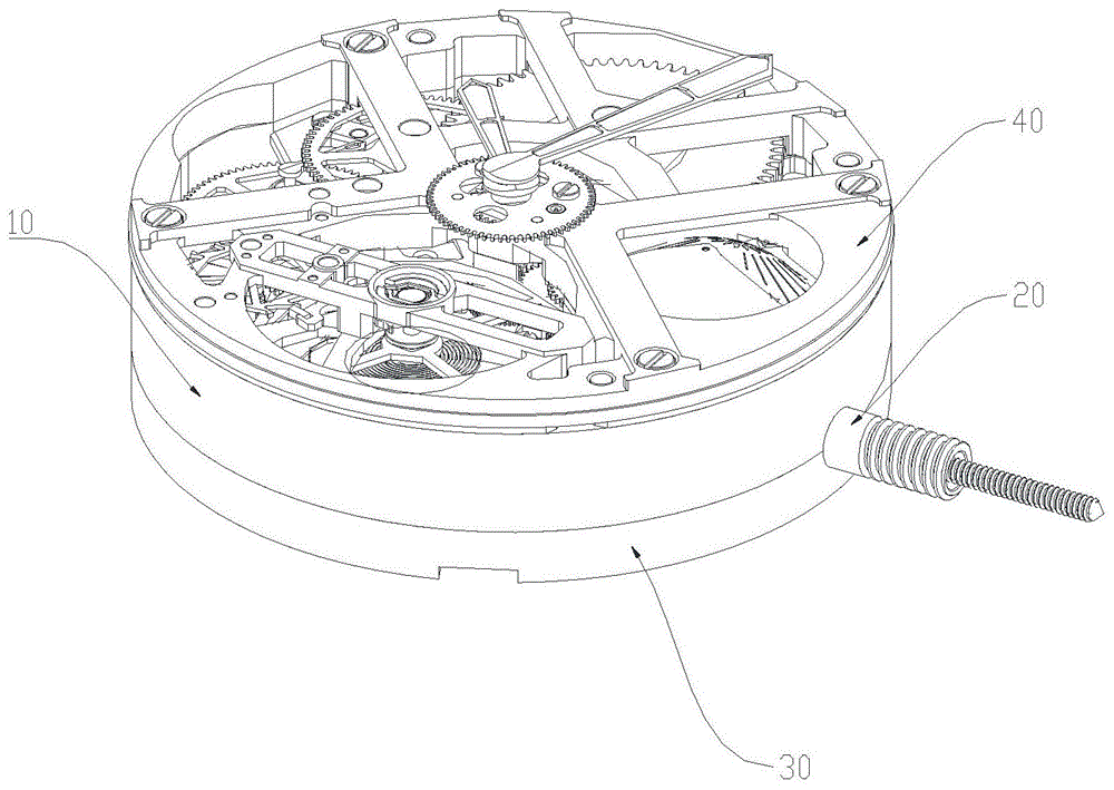
As shown in fig. 1 to fig. 6, the present invention discloses a mechanical dynamic movement structure of an electronic hand-manipulating timing belt, which comprises a main plate 10, a winding rack mechanism 20, a hand-manipulating transmission mechanism 30 and a mechanical dynamic mechanism 40, wherein the winding rack mechanism 20, the hand-manipulating transmission mechanism 30 and the mechanical dynamic mechanism 40 are connected with the main plate 10; the needle-manipulating transmission mechanism 30 and the mechanical dynamic mechanism 40 are also connected with the upper rack gear mechanism 20; the winding gear mechanism 20 comprises a lower clamping plate 21, a vertical wheel sleeve 22, a first winding passing wheel 23, a second winding passing wheel 24, a winding ratchet wheel 25 and a spring barrel 26; the lower clamp plate 21 is connected with the lower part of the main clamp plate 10, the vertical wheel sleeve 22 is connected with the needle transmission mechanism 30, the lower part of the lower clamp plate 21 is connected with the needle transmission mechanism 30, the first winding passing wheel 23, the second winding passing wheel 24 and the winding ratchet wheel 25 are arranged on the upper part of the lower clamp plate 21, an open slot 211 is further arranged on one side of the lower clamp plate 21, the gear end of the vertical wheel sleeve 22 protrudes out of the open slot 211 to be in transmission connection with the first winding passing wheel 23, the second winding passing wheel 24 is in transmission connection with the first winding passing wheel 23, the winding ratchet wheel 25 is in transmission connection with the second winding passing wheel 24, the spring box 26 is connected with the main clamp plate 10, the lower part of the spring box 26 penetrates through the main clamp plate 10 to be in transmission connection with the winding ratchet wheel 25, and the vertical wheel sleeve 22 is rotated by adjusting the timing core 32, thereby driving the first winding wheel 23 to rotate, then driving the second winding wheel 24 to rotate through the first winding wheel 23, then driving the winding ratchet wheel 25 to rotate through the second winding wheel 24, and finally driving the spring box 26 to rotate through the winding ratchet wheel 25, so that the spring box 26 can complete the winding function.
As shown in fig. 2, a pawl 27 is further disposed on the upper portion of the lower clamp plate 21, and the pawl 27 is connected to the winding ratchet wheel 25, so that the winding ratchet wheel 25 is guaranteed to rotate in one direction and never rotate in the opposite direction.
As shown in fig. 2 to 5, the hand manipulating transmission mechanism 30 includes a hand manipulating movement 31, a timing handle movement 32, a first movement third wheel 33, a second movement third wheel 34, a third movement third wheel 35, a fourth movement third wheel 36, a minute wheel shaft component 37, and a time wheel shaft component 38; the hour hand movement 31 is arranged at the lower part of the lower clamp plate 21, the hour hand movement 32 is sleeved with the vertical wheel sleeve 22, one end of the hour hand movement 32 penetrates through the vertical wheel sleeve 22 to be connected with the hour hand movement 31, the hour hand movement 31 is further provided with a minute wheel shaft 311, the first machine core third wheel 33 is in transmission connection with the minute wheel shaft 311, the second machine core third wheel 34 is arranged at the upper part of the lower clamp plate 21 and is in transmission connection with the first machine core third wheel 33, the minute wheel shaft 37 is arranged at the upper part of the lower clamp plate 21 and is in transmission connection with the second machine core third wheel 34, the third machine core third wheel 35 is arranged on the main clamp plate 10 and is in transmission connection with the minute wheel shaft 37, the fourth machine core third wheel 36 is arranged on the main clamp plate 10 and is in transmission connection with the minute wheel shaft 37, the hour wheel 38 is arranged on the mechanical dynamic mechanism (namely the upper clamp plate 41), And is in transmission connection with the third movement third wheel 35.
Wherein, when the timing is extracted the back to core 32's ba, just can adjust the timing and do not influence barrel 26 for electronic quartz hand-manipulating watch movement mechanism timing uses a ba cheng with mechanical core winding mechanism jointly, and kinetic energy operation between them can not receive the influence each other again, has simplified electronic quartz hand-manipulating movement greatly and has combined integrative structural design with mechanical core.
As shown in fig. 5, the needle transmission mechanism 30 further includes a display member 39 connected to the main plate 10; the display part 39 is in transmission connection with the third movement idler wheel 36, so that time and minutes can be accurately displayed.
As shown in fig. 5, the needle moving transmission mechanism 30 further includes a display plate 391, the display plate 391 is located above the display member 39 and connected to the main plate 10, and the display plate 391 is used for fixing the display member 39, so that the display member 39 is firmly connected and stably rotates.
As shown in fig. 5, the hand-manipulating transmission mechanism 30 further includes a core over wheel clamp plate 341, the core over wheel clamp plate 341 is located above the second core over wheel 34 and connected to the lower clamp plate 21, and the core over wheel clamp plate 341 is configured to fix the second core over wheel 34, so that the second core over wheel 34 is connected firmly and transmission is stable.
As shown in fig. 6, the mechanical motion sensing mechanism 40 includes an upper plate 41, a second wheel member 42, a third wheel member 43, a second wheel member 44, a first mechanical transmission wheel 45, a second mechanical transmission wheel 46, an escape wheel member 47, a pallet fork member 48, and a balance member 49; the upper plate 41 is connected to the upper portion of the main plate 10, the second wheel component 42 is disposed between the main plate 10 and the upper plate 41 and is in transmission connection with the spring barrel 26, the third wheel component 43 is disposed between the main plate 10 and the upper plate 41 and is in transmission connection with the second wheel component 42, the second wheel component 44 is disposed on the main plate 10 and is in transmission connection with the third wheel component 43, the first mechanical transmission wheel 45 is disposed on the main plate 10 and is in transmission connection with the second wheel component 44, the second mechanical transmission wheel 46 is disposed on the main plate 10 and is in transmission connection with the first mechanical transmission wheel 45, the escape wheel component 47 is disposed on the upper plate 41 and is in transmission connection with the second mechanical transmission wheel 46, the escape fork component 48 is disposed between the main plate 10 and the upper plate 41, And is in transmission connection with the escape wheel component 47, the balance wheel component 49 is arranged on the main plate 10 and is in transmission connection with the escape fork component 48, so that the balance wheel component 49 pushes the escape fork component 48 and the escape wheel component 47 to release energy under the fixed oscillation frequency of the balance spring, and the traditional mechanical pallet-stone escapement principle is displayed on the watch movement.
As shown in fig. 6, the mechanical motion sensing mechanism 40 further includes a second shaft clamping plate 441, the second shaft clamping plate 441 is positioned above the second shaft part 44 and connected to the main clamping plate 10, and the second shaft clamping plate 441 is used for fixing the second shaft part 44, so that the second shaft part 44 is firmly connected and stably driven.
As shown in fig. 6, the mechanical dynamic mechanism 40 further includes a mechanical transmission wheel clamp plate 451, the mechanical transmission wheel clamp plate 451 is located below the first mechanical transmission wheel 45 and the second mechanical transmission wheel 46 and connected to the main clamp plate 10, and the mechanical transmission wheel clamp plate 451 is used to fix the first mechanical transmission wheel 45 and the second mechanical transmission wheel 46, so that the first mechanical transmission wheel 45 and the second mechanical transmission wheel 46 are firmly connected and stably transmitted.
As shown in fig. 6, the mechanical dynamic mechanism 40 further includes a balance cock 491, the balance cock 491 is located below the balance member 49 and connected to the main cock 10, and the balance cock 491 fixes the balance member 49, so that the balance member 49 is firmly connected and the transmission is stable.
The invention combines the hand transmission mechanism and the mechanical dynamic mechanism to form a simple and feasible time-adjusting winding mechanism, has the functions of the electronic quartz hand watch of accurate and long-time continuous work, has unique timing dynamic and aesthetic state of the mechanical movement at the same time, and can better meet the requirements of consumers.
The above embodiments are preferred implementations of the present invention, and the present invention can be implemented in other ways without departing from the spirit of the present invention.