CN113087277A - Sedimentation device and sedimentation method for wastewater treatment - Google Patents
Sedimentation device and sedimentation method for wastewater treatment Download PDFInfo
- Publication number
- CN113087277A CN113087277A CN202110567976.7A CN202110567976A CN113087277A CN 113087277 A CN113087277 A CN 113087277A CN 202110567976 A CN202110567976 A CN 202110567976A CN 113087277 A CN113087277 A CN 113087277A
- Authority
- CN
- China
- Prior art keywords
- tank body
- transmission rod
- baffle
- pool
- wastewater
- Prior art date
- Legal status (The legal status is an assumption and is not a legal conclusion. Google has not performed a legal analysis and makes no representation as to the accuracy of the status listed.)
- Pending
Links
- 238000004062 sedimentation Methods 0.000 title claims abstract description 39
- 238000004065 wastewater treatment Methods 0.000 title claims abstract description 22
- 238000000034 method Methods 0.000 title claims description 14
- 239000002351 wastewater Substances 0.000 claims abstract description 43
- 239000013049 sediment Substances 0.000 claims abstract description 31
- 238000004140 cleaning Methods 0.000 claims abstract description 30
- XLYOFNOQVPJJNP-UHFFFAOYSA-N water Substances O XLYOFNOQVPJJNP-UHFFFAOYSA-N 0.000 claims abstract description 30
- 230000005540 biological transmission Effects 0.000 claims description 49
- 239000003344 environmental pollutant Substances 0.000 claims description 21
- 231100000719 pollutant Toxicity 0.000 claims description 21
- 239000008394 flocculating agent Substances 0.000 claims description 13
- 238000005507 spraying Methods 0.000 claims description 8
- 238000007599 discharging Methods 0.000 claims description 4
- 238000005189 flocculation Methods 0.000 claims description 3
- 230000016615 flocculation Effects 0.000 claims description 3
- 239000007921 spray Substances 0.000 claims description 2
- 239000002344 surface layer Substances 0.000 claims description 2
- 210000005056 cell body Anatomy 0.000 description 9
- 239000000356 contaminant Substances 0.000 description 4
- 239000002244 precipitate Substances 0.000 description 4
- 238000007664 blowing Methods 0.000 description 3
- 238000001914 filtration Methods 0.000 description 3
- 239000002245 particle Substances 0.000 description 2
- 238000003756 stirring Methods 0.000 description 2
- 239000000126 substance Substances 0.000 description 2
- 239000002028 Biomass Substances 0.000 description 1
- 230000009286 beneficial effect Effects 0.000 description 1
- 238000010170 biological method Methods 0.000 description 1
- 230000007797 corrosion Effects 0.000 description 1
- 238000005260 corrosion Methods 0.000 description 1
- 230000003670 easy-to-clean Effects 0.000 description 1
- 230000002349 favourable effect Effects 0.000 description 1
- 230000005484 gravity Effects 0.000 description 1
- 238000010030 laminating Methods 0.000 description 1
- 239000007788 liquid Substances 0.000 description 1
- 238000012423 maintenance Methods 0.000 description 1
- 238000012986 modification Methods 0.000 description 1
- 230000004048 modification Effects 0.000 description 1
- 230000002035 prolonged effect Effects 0.000 description 1
- 239000007787 solid Substances 0.000 description 1
Images


Classifications
-
- C—CHEMISTRY; METALLURGY
- C02—TREATMENT OF WATER, WASTE WATER, SEWAGE, OR SLUDGE
- C02F—TREATMENT OF WATER, WASTE WATER, SEWAGE, OR SLUDGE
- C02F9/00—Multistage treatment of water, waste water or sewage
-
- C—CHEMISTRY; METALLURGY
- C02—TREATMENT OF WATER, WASTE WATER, SEWAGE, OR SLUDGE
- C02F—TREATMENT OF WATER, WASTE WATER, SEWAGE, OR SLUDGE
- C02F1/00—Treatment of water, waste water, or sewage
- C02F1/48—Treatment of water, waste water, or sewage with magnetic or electric fields
- C02F1/484—Treatment of water, waste water, or sewage with magnetic or electric fields using electromagnets
-
- C—CHEMISTRY; METALLURGY
- C02—TREATMENT OF WATER, WASTE WATER, SEWAGE, OR SLUDGE
- C02F—TREATMENT OF WATER, WASTE WATER, SEWAGE, OR SLUDGE
- C02F1/00—Treatment of water, waste water, or sewage
- C02F1/52—Treatment of water, waste water, or sewage by flocculation or precipitation of suspended impurities
-
- C—CHEMISTRY; METALLURGY
- C02—TREATMENT OF WATER, WASTE WATER, SEWAGE, OR SLUDGE
- C02F—TREATMENT OF WATER, WASTE WATER, SEWAGE, OR SLUDGE
- C02F1/00—Treatment of water, waste water, or sewage
- C02F2001/007—Processes including a sedimentation step
Abstract
The invention relates to the field of wastewater treatment, in particular to a sedimentation device for wastewater treatment. A sedimentation device for wastewater treatment comprises a tank body, a water inlet arranged above the tank body, a water outlet arranged on the tank wall of the tank body, a collecting device arranged on the inner bottom surface of the tank body and used for concentrating sediments at the bottom of the tank body, and a cleaning device arranged on one side of the inner bottom surface of the tank body, which is close to the tank wall, and used for removing the concentrated sediments out of the tank body, wherein the collecting device comprises a baffle plate which is movably arranged at the inner bottom of the tank body, and two ends of the baffle plate are in clearance fit with the tank wall; the linear driver is arranged on the outer top surface of the tank body and used for driving the baffle plate to move sediments at the bottom of the tank to a working area of the cleaning equipment; and the rotary driver is arranged on the linear driver and used for driving the baffle to switch between a state of being vertical to the pool bottom and a state of being parallel to the pool bottom. According to the invention, through the cooperation of the collecting device and the cleaning device, the sediment is cleaned while the sediment device is used for treating the wastewater, so that the wastewater treatment efficiency is improved.
Description
Technical Field
The invention relates to the field of wastewater treatment, in particular to a sedimentation device and a sedimentation method for wastewater treatment.
Background
The wastewater treatment is to treat the wastewater by physical, chemical and biological methods, so that the wastewater is purified, the pollution is reduced, the wastewater is recycled and reused, and water resources are fully utilized. Separating the pollutants from the waste water or converting the pollutants into harmless substances.
When the wastewater is treated at present, the wastewater is usually treated by using a sedimentation treatment mode, and the following technical problems can occur in the process: the sedimentation device accumulates a large amount of precipitates in the process of carrying out sedimentation treatment on wastewater, and the precipitates cannot be conveniently cleaned, so that the efficiency of the sedimentation device is reduced or the sedimentation device fails.
Disclosure of Invention
In order to solve the technical problem, a settling device for wastewater treatment is provided.
In order to achieve the above purposes, the technical scheme adopted by the invention is as follows:
a sedimentation device for wastewater treatment comprises a tank body, a water inlet arranged above the tank body, a water outlet arranged on the tank wall of the tank body, a collecting device arranged on the inner bottom surface of the tank body and used for concentrating sediments at the bottom of the tank body, a cleaning device arranged on one side of the inner bottom surface of the tank body, which is close to the tank wall, and used for removing the concentrated sediments out of the tank body,
the collecting device comprises a collecting device and a collecting device,
the baffle is movably arranged at the bottom in the tank body, and two ends of the baffle are in clearance fit with the tank wall;
the linear driver is arranged on the outer top surface of the tank body and used for driving the baffle plate to move sediments at the bottom of the tank to a working area of the cleaning equipment;
and the rotary driver is arranged on the linear driver and used for driving the baffle to switch between two states of being vertical to the bottom of the pool and being parallel to the bottom of the pool.
Preferably, the linear actuator comprises, in combination,
the two first sliding rails are respectively and symmetrically arranged on the outer top surface of the tank body along the length direction of the tank body;
the sliding blocks are arranged on the first sliding rails, and two ends of each sliding block are respectively in sliding fit with the corresponding first sliding rails;
the connecting rod is vertically arranged on the bottom surface of the sliding block, the top end of the connecting rod is fixedly connected with the sliding block, and the bottom end of the connecting rod is rotatably connected with the baffle;
the rack is fixedly arranged on the first sliding rail along the length of the first sliding rail;
the first motor is fixedly arranged on the sliding block, a first cylindrical gear is arranged on the output end of the first motor, and the first cylindrical gear is meshed with the rack.
Preferably, the rotary drive comprises, in combination,
the first transmission rod is rotatably and transversely inserted at the bottom of the connecting rod and is fixedly connected with the baffle;
the first bevel gear is arranged at one end of the first transmission rod and is fixedly connected with the first transmission rod;
the mounting seat is fixedly arranged on the side surface of the connecting rod, and a vertical through hole is formed in the mounting seat;
the second transmission rod is vertically inserted into the through hole of the mounting seat and is rotatably connected with the mounting seat;
the second bevel gear is arranged at the bottom end of the second transmission rod and fixedly connected with the second transmission rod, and the second bevel gear is meshed with the first bevel gear;
the second cylindrical gear is fixedly arranged at the top end of the second transmission rod and is fixedly connected with the top end of the second transmission rod;
the second motor is fixedly arranged on the sliding block, a third cylindrical gear is arranged on the output end of the second motor, the third cylindrical gear is fixedly connected with the output end of the second motor, and the third cylindrical gear is meshed with the second cylindrical gear.
Preferably, one side of the inner bottom surface of the tank body, which is close to the tank wall, is provided with a groove with the same width as the tank body, the cleaning equipment comprises,
the collecting box is movably arranged in the groove, and a connecting piece is arranged at the top end of the collecting box;
two second sliding rails are vertically arranged on two sides of the groove respectively and are connected with the collecting box in a sliding manner;
the winch is fixedly arranged on the outer top surface of the tank body and is positioned right above the center of the collecting box;
the haulage rope, the haulage rope setting is on the hoist engine, the one end of haulage rope and the output fixed connection of hoist engine, the other end and the connecting piece fixed connection of haulage rope.
Preferably, the sedimentation device also comprises flocculant spraying equipment, wherein the flocculant spraying equipment comprises a portal frame, and the portal frame is fixedly arranged on the outer top surface of the tank body;
the third transmission rod is rotatably and vertically inserted on the portal frame and is positioned at the center above the pool body;
the output end of the third motor is fixedly connected with the top end of the third transmission rod;
the straight pipe is transversely arranged at the bottom end of the third transmission rod and fixedly connected with the third transmission rod, and an input port for inputting the flocculating agent is formed in the straight pipe;
and the output end of the nozzle is downwards arranged on the straight pipe, and the nozzle is communicated with the flocculating agent in the straight pipe.
Preferably, a plurality of electromagnets are arranged below the bottom of the tank body.
Preferably, the sedimentation device is further provided with a filter screen on the water outlet.
Compared with the prior art, the invention has the beneficial effects that:
1. according to the invention, the flocculating agent is uniformly sprayed into the wastewater by the flocculating agent spraying equipment, so that the sediment is prevented from being mixed with the wastewater again due to the stirring of the wastewater;
2. according to the invention, through the cooperation of the collecting equipment and the cleaning equipment, sediments at the bottom of the pool are effectively and conveniently cleaned, the traditional cleaning mode that the waste water in the pool body needs to be drained for cleaning is avoided, the sedimentation efficiency is improved, and the cleaning cost is reduced;
3. the motor and the important transmission assembly are arranged outside the tank body, so that the contact with wastewater is avoided, the practical service life of the device is prolonged, and the maintenance cost is reduced;
4. according to the invention, the electromagnet is arranged below the bottom of the tank body, so that the magnetic pollutants are accelerated to settle, the settling process is accelerated, and the wastewater treatment efficiency is improved.
Drawings
FIG. 1 is a side view of the present invention;
FIG. 2 is a first perspective view of the present invention;
FIG. 3 is a second perspective view of the present invention;
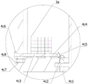
FIG. 4 is an enlarged view of a portion of FIG. 3;
FIG. 5 is a front view of the present invention;
FIG. 6 is a top view 1 of the present invention;
FIG. 7 is a cross-sectional view taken at A-A of FIG. 6;
FIG. 8 is a top view 2 of the present invention;
FIG. 9 is a cross-sectional view taken at B-B of FIG. 8;
FIG. 10 is an enlarged view of a portion of FIG. 9 at B;
the reference numbers in the figures are:
1-a pool body; 1 a-a groove;
2-a water inlet;
3-water outlet; 3 a-a filter screen;
4-a collecting device; 4 a-a baffle; 4 b-linear drive; 4b1 — first slide rail; 4b2 — slide; 4b 3-Link; 4b 4-rack; 4b5 — first motor; 4b6 — first spur gear; 4 c-a first rotary drive; 4c1 — first transfer lever; 4c2 — first bevel gear; 4c 3-mount; 4c4 — second transfer bar; 4c5 — second bevel gear; 4c6 — second spur gear; 4c7 — a second motor; 4c 8-third spur gear;
5-cleaning the equipment; 5 a-a collection box; 5a 1-connectors; 5 b-a winch; 5 c-a second slide rail; 5 d-a traction rope;
6-flocculant spraying equipment; 6 a-a portal frame; 6 b-a third transmission rod; 6 c-a third motor; 6 d-straight pipe; 6 e-a nozzle;
7-electromagnet.
Detailed Description
The following description is presented to disclose the invention so as to enable any person skilled in the art to practice the invention. The preferred embodiments in the following description are given by way of example only, and other obvious variations will occur to those skilled in the art.
In order to solve the technical problem of how to treat wastewater through sedimentation, as shown in fig. 1-3 and fig. 7, the following technical scheme is provided:
a sedimentation device for wastewater treatment comprises a tank body 1, a water inlet 2 arranged above the tank body 1, a water outlet 3 arranged on the wall of the tank body 1, a collecting device 4 arranged on the inner bottom surface of the tank body 1 and used for concentrating sediments at the bottom of the tank, a cleaning device 5 arranged on one side of the inner bottom surface of the tank body 1 close to the tank wall and used for removing the concentrated sediments out of the tank body 1,
the collecting device 4 comprises a device for collecting the liquid,
the baffle 4a is movably arranged at the bottom in the tank body 1, and two ends of the baffle 4a are in clearance fit with the tank wall;
the linear driver 4b is arranged on the outer top surface of the tank body 1 and used for driving the baffle 4a to move sediments at the bottom of the tank to a working area of the cleaning equipment 5;
a rotary driver 4c, the rotary driver 4c is arranged on the linear driver 4b and is used for driving the baffle plate 4a to switch between a state of being vertical to the bottom of the pool and a state of being parallel to the bottom of the pool.
Specifically, the linear driver 4b and the rotary driver 4c are both arranged outside the tank body 1, so as to avoid the damage caused by the contact corrosion of the first motor 4b5 caused by wastewater for a long time, after the wastewater is poured into the tank body 1 through the water inlet 2, pollutant particles with density higher than that of water in the wastewater naturally settle to the bottom of the tank body 1 under the action of gravity, the wastewater flows out from the water outlet 3 after sedimentation and filtration, when sediments at the bottom of the tank need to be cleaned, a worker can use the linear driver 4b to move the baffle 4a vertical to the bottom of the tank from one side of the tank wall farthest from the cleaning equipment 5 to the working area of the cleaning equipment 5, the baffle 4a pushes the sediments at the bottom of the tank to the working area of the cleaning equipment 5 in the moving process, the cleaning equipment 5 moves the concentrated sediments out of the tank body 1, the rotary driver 4c drives the baffle 4a to be switched from the state vertical to the bottom of the tank to the state parallel to the, the baffle 4a is prevented from bringing back the residual sediment in the process of resetting the linear driver 4b, and after the linear driver 4b is reset, the rotary driver 4c drives the baffle 4a to be reset to be vertical to the bottom of the pool from a state of being parallel to the bottom of the pool.
Further:
in order to solve the technical problem of realizing that the linear driver 4b is arranged outside the tank body 1 and simultaneously drives the baffle 4a to move, as shown in fig. 6, the following technical scheme is provided:
the linear actuator 4b comprises a linear actuator,
two first slide rails 4b1 and two first slide rails 4b1 are symmetrically arranged on the outer top surface of the tank body 1 along the length direction of the tank body 1;
the sliding block 4b2, the sliding block 4b2 is arranged on the first sliding rail 4b1, and two ends of the sliding block 4b2 are respectively matched with the corresponding first sliding rail 4b1 in a sliding way;
the connecting rod 4b3 is characterized in that the connecting rod 4b3 is vertically arranged on the bottom surface of the sliding block 4b2, the top end of the connecting rod 4b3 is fixedly connected with the sliding block 4b2, and the bottom end of the connecting rod 4b3 is rotatably connected with the baffle 4 a;
a rack 4b4, the rack 4b4 being fixedly disposed on the first slide rail 4b1 along the length of the first slide rail 4b 1;
the first motor 4b5, the first motor 4b5 is fixed on the slider 4b2, the output end of the first motor 4b5 is provided with a first cylindrical gear 4b6, and the first cylindrical gear 4b6 is meshed with the rack 4b 4.
Specifically, the first motor 4b5 drives the first cylindrical gear 4b6 to rotate, the first cylindrical gear 4b6 and the rack 4b4 cooperate to drive the slider 4b2 to slide on the first slide rail 4b1, and the slider 4b2 drives the connecting rod 4b3 and the baffle 4a connected to the connecting rod 4b3 to move.
Further:
in order to solve the technical problem of how to realize that the rotary driver 4c is arranged outside the tank body 1 and can drive the baffle 4a in the tank body 1 to rotate, as shown in fig. 10, the following technical scheme is provided:
the rotary drive 4c is comprised of,
the first driving rod 4c1, the first driving rod 4c1 is transversely inserted at the bottom of the connecting rod 4b3 in a rotatable manner, and the first driving rod 4c1 is fixedly connected with the baffle 4 a;
the first bevel gear 4c2, the first bevel gear 4c2 is arranged at one end of the first driving rod 4c1, and the first bevel gear 4c2 is fixedly connected with the first driving rod 4c 1;
the mounting seat 4c3 is characterized in that the mounting seat 4c3 is fixedly arranged on the side surface of the connecting rod 4b3, and a vertical through hole is formed in the mounting seat 4c 3;
the second transmission rod 4c4, the second transmission rod 4c4 is vertically inserted into the through hole of the mounting seat 4c3, and the second transmission rod 4c4 is rotatably connected with the mounting seat 4c 3;
the second bevel gear 4c5, the second bevel gear 4c5 is arranged at the bottom end of the second transmission rod 4c4, the second bevel gear 4c5 is fixedly connected with the second transmission rod 4c4, and the second bevel gear 4c5 is meshed with the first bevel gear 4c 2;
the second cylindrical gear 4c6, the second cylindrical gear 4c6 is fixedly arranged at the top end of the second transmission rod 4c4, and the second cylindrical gear 4c6 is fixedly connected with the top end of the second transmission rod 4c 4;
the second motor 4c7, the second motor 4c7 is fixedly arranged on the sliding block 4b2, the output end of the second motor 4c7 is provided with a third cylindrical gear 4c8, the third cylindrical gear 4c8 is fixedly connected with the output end of the second motor 4c7, and the third cylindrical gear 4c8 and the second cylindrical gear 4c6 are meshed with each other.
Specifically, the worker drives the second motor 4c7 to rotate, the third cylindrical gear 4c8 at the output end of the second motor 4c7 cooperates with the second cylindrical gear 4c6 to drive the second transmission rod 4c4 to rotate along the self axis, the second bevel gear 4c5 follows the second transmission rod 4c4 to rotate, the second bevel gear 4c5 cooperates with the first bevel gear 4c2 to drive the first transmission rod 4c1 to rotate along the self axis, the baffle 4a follows the first transmission rod 4c1 fixedly connected with the baffle 4a to rotate along the axis of the first transmission rod 4c1, and switching between the state of being perpendicular to the bottom of the pool and the state of being parallel to the bottom of the pool is completed.
Further:
in order to solve the technical problem of how to realize removing the collected sediments from the tank body 1 without discharging dry wastewater, as shown in fig. 4 and 6-7, the following technical scheme is provided:
one side of the inner bottom surface of the tank body 1 close to the tank wall is provided with a groove 1a with the same width as the tank body 1, the cleaning device 5 comprises,
the collecting box 5a is movably arranged in the groove 1a, and the top end of the collecting box 5a is provided with a connecting piece 5a 1;
two second slide rails 5c are arranged, the two second slide rails 5c are respectively vertically arranged at two sides of the groove 1a, and the second slide rails 5c are connected with the collection box 5a in a sliding manner;
the winch 5b is fixedly arranged on the outer top surface of the tank body 1, and the winch 5b is positioned right above the center of the collection box 5 a;
Concretely, hoist engine 5b sets up the top surface outside the cell body 1, avoided causing the damage with the waste water contact, move to the top of groove 1a from the pond wall of cleaning equipment 5 opposite face when linear drive ware 4b drive baffle 4a, in the precipitate in the pond is concentrated to the collection box 5a in groove 1a, hoist engine 5b drive haulage rope 5d rotates around hoist engine 5b this moment, haulage rope 5d is tightened up and is driven connecting piece 5a1 and collection box 5a be connected with it, it rises to cell body 1 top along second slide rail 5c and clears up to collect box 5a, realized not letting dry waste water simultaneously with the precipitate of cell body 1 bottom shift out the function of cell body 1.
Further:
in order to solve the technical problem of how to accelerate the sedimentation of pollutant particles in water, as shown in fig. 5 and 7, the following technical solutions are provided:
the sedimentation device also comprises flocculant spraying equipment 6, wherein the flocculant spraying equipment 6 comprises a portal frame 6a, and the portal frame 6a is fixedly arranged on the outer top surface of the tank body 1;
the third transmission rod 6b is vertically inserted on the portal frame 6a in a rotatable manner, and the third transmission rod 6b is positioned at the center position above the pool body 1;
the third motor 6c is fixedly arranged on the portal frame 6a, and the output end of the third motor 6c is fixedly connected with the top end of the third transmission rod 6 b;
the straight pipe 6d is transversely arranged at the bottom end of the third transmission rod 6b, the straight pipe 6d is fixedly connected with the third transmission rod 6b, and an input port for inputting a flocculating agent is formed in the straight pipe 6 d;
and the output end of the nozzle 6e is downwards arranged on the straight pipe 6d, and the nozzle 6e is communicated with the flocculating agent in the straight pipe 6 d.
Concretely, the flocculating agent can be with higher speed solid and gelatinous pollutant in the waste water and condense, subside, and the staff can drive third transfer line 6b through third motor 6c and drive straight tube 6d and rotate along third transfer line 6b axis, with the flocculating agent through the even waste water that sprays to cell body 1 of nozzle 6e on the straight tube 6d, maximize when not stirring waste water with the flocculating agent compatible with waste water with higher speed, reduce the time of natural sedimentation.
Further:
in order to solve the technical problem of how to further reduce the settling waiting time, as shown in fig. 9, the following technical solutions are provided:
a plurality of electromagnets 7 are arranged below the bottom of the tank body 1.
Specifically, often have partial magnetic contaminant in the waste water, the electro-magnet 7 of setting in 1 bottom below of cell body can accelerate magnetic contaminant's settling velocity, and magnetic contaminant can drive the flocculation group at self place and sink with higher speed at the in-process that subsides to make the subsides and the laminating of bottom of the pool, be favorable to the collection of baffle 4a to the bottom of the pool subsides.
Further:
in order to solve the technical problem of how to filter contaminants having a density lower than that of water, as shown in fig. 10, the following technical solutions are provided:
the sedimentation device is also provided with a filter screen 3a on the water outlet 3.
Specifically, the filter screen 3a is used for filtering pollutants with density lower than that of water in the wastewater, the pollutants with density lower than that of water can float on the water surface, and workers can remove the pollutants floating on the surface of the wastewater through regular manual fishing.
In addition, as shown in fig. 9, a circular groove is formed in the bottom of the cell body 1, and a circular rotating plate 1b which is rotatably connected to the opening of the circular groove and seals the opening of the circular groove, a sealed chamber is formed, the inner wall and the outer wall of the circular rotating plate 1b are sealed with the corresponding groove walls of the circular groove, a driving motor 1c is connected to one side of the circular groove close to the bottom of the circular groove, a driving gear body 1d is connected to an output shaft of the driving motor 1c, engaging teeth which are engaged with the driving gear body 1d and are uniformly distributed in the circumference are arranged on the lower surface of the circular rotating plate 1b, the driving motor 1c is started and drives the driving gear body 1d engaged with the engaging teeth to rotate, the circular rotating plate 1b is also driven to rotate, a vortex is formed in the cell body 1 at the moment, a treated object can be stirred in advance, and simultaneously, the inner wall of the cell body.
Secondly, the upper surface of the circular rotating plate 1b is flush with the upper surface of the bottom of the tank body 1, so as to prevent sediment from being deposited and not easy to clean.
In addition, a plurality of unidirectional high-pressure air blowing nozzles 1e which are uniformly distributed in the circumferential direction are arranged on the circular rotating plate 1b, the air inlet ends of the unidirectional high-pressure air blowing nozzles 1e are communicated with the sealed cavity, and the sealed cavity is connected with the compressor through a high-pressure air supply pipe.
When the sediment is cleaned, the baffle 4a moves back and forth, the one-way high-pressure air blowing nozzle 1e blows air at the moment in the moving process, and residues attached to the vertical two vertical surfaces of the baffle 4a and the plane close to the pool bottom are cleaned due to the impact force of upward high-pressure air flow when the baffle 4a moves back and forth, so that the service life of the baffle 4a is ensured.
The working principle of the invention is as follows:
step one, wastewater is discharged into a tank body 1 through a water inlet 2, pollutants insoluble in water in the wastewater are separated through natural sedimentation, the density of the pollutants is higher than that of the pollutants of the water and sinks to the bottom of the tank body 1, and the density of the pollutants is lower than that of the pollutants of the water and floats to the surface layer of the wastewater;
step two, the straight pipe 6d is driven by the third motor 6c to rotate along the axis of the third transmission rod 6b, and the flocculating agent is uniformly sprayed into the wastewater by the nozzle 6e to accelerate sedimentation;
thirdly, electrifying and magnetizing the electromagnet 7, and adsorbing the magnetic pollutants and the flocculation groups in the wastewater to the bottom of the biomass pool body 1 to accelerate sedimentation;
step four, discharging the wastewater from the tank body 1 through a water outlet 3 after settling and filtering;
step five, the first linear driver 4b drives the baffle 4a vertical to the pool bottom to move from one end of the pool bottom to the working area of the cleaning equipment 5 at the other end, and the baffle 4a pushes the sediment at the bottom of the pool bottom to the working area of the cleaning equipment 5 in the moving process;
sixthly, after the sediments at the bottom of the tank are concentrated in the working area of the cleaning equipment 5, the winch 5b drives the traction rope 5d to be retracted, and the collection box 5a at the bottom of the tank drives the sediments at the bottom of the tank to rise to the top of the tank body 1 together for cleaning;
seventhly, the collecting box 5a is reset, the rotary driver 4c drives the baffle 4a to be switched from the state of being vertical to the pool bottom to the state of being parallel to the pool bottom, the linear driver 4b drives the baffle 4a to be reset, and the rotary driver 4c drives the baffle 4a to be switched from the state of being parallel to the pool bottom to the state of being vertical to the pool bottom;
step eight, repeating the step one to the step four until all the wastewater is treated;
and step nine, repeating the step five to the step seven until all the sediments are cleaned.
The foregoing shows and describes the general principles, essential features, and advantages of the invention. It will be understood by those skilled in the art that the present invention is not limited to the embodiments described above, which are merely illustrative of the principles of the invention, but that various changes and modifications may be made without departing from the spirit and scope of the invention, which fall within the scope of the invention as claimed. The scope of the invention is defined by the appended claims and equivalents thereof.
Claims (8)
1. A sedimentation device for wastewater treatment comprises a tank body (1), a water inlet (2) arranged above the tank body (1), a water outlet (3) arranged on the tank wall of the tank body (1), a collecting device (4) arranged on the inner bottom surface of the tank body (1) and used for concentrating sediments at the bottom of the tank, a cleaning device (5) arranged on one side of the inner bottom surface of the tank body (1) close to the tank wall and used for moving the concentrated sediments out of the tank body (1),
characterized in that the collecting device (4) comprises,
the baffle (4a) is movably arranged at the bottom in the tank body (1), and two ends of the baffle (4a) are in clearance fit with the tank wall;
the linear driver (4b), the linear driver (4b) is arranged on the outer top surface of the tank body (1) and is used for driving the baffle (4a) to move the sediment at the bottom of the tank to the working area of the cleaning equipment (5);
a rotary driver (4c), the rotary driver (4c) is arranged on the linear driver (4b) and is used for driving the baffle (4a) to switch between a state of being vertical to the bottom of the pool and a state of being parallel to the bottom of the pool.
2. A sedimentation device for wastewater treatment according to claim 1, characterized in that the linear drive (4b) comprises,
two first slide rails (4b1), wherein the two first slide rails (4b1) are respectively and symmetrically arranged on the outer top surface of the tank body (1) along the length direction of the tank body (1);
the sliding block (4b2), the sliding block (4b2) is arranged on the first sliding rail (4b1), and two ends of the sliding block (4b2) are respectively in sliding fit with the corresponding first sliding rail (4b 1);
the connecting rod (4b3), the connecting rod (4b3) is vertically arranged on the bottom surface of the sliding block (4b2), the top end of the connecting rod (4b3) is fixedly connected with the sliding block (4b2), and the bottom end of the connecting rod (4b3) is rotatably connected with the baffle (4 a);
the rack (4b4), the rack (4b4) is fixedly arranged on the first slide rail (4b1) along the length of the first slide rail (4b 1);
the first motor (4b5), the first motor (4b5) is fixedly arranged on the sliding block (4b2), the output end of the first motor (4b5) is provided with a first cylindrical gear (4b6), and the first cylindrical gear (4b6) is meshed with the rack (4b 4).
3. A sedimentation device for wastewater treatment according to claim 2, characterized in that the rotary drive (4c) comprises,
the first transmission rod (4c1), the first transmission rod (4c1) is transversely inserted at the bottom of the connecting rod (4b3) in a rotatable manner, and the first transmission rod (4c1) is fixedly connected with the baffle (4 a);
the first bevel gear (4c2), the first bevel gear (4c2) is arranged at one end of the first driving rod (4c1), and the first bevel gear (4c2) is fixedly connected with the first driving rod (4c 1);
the mounting seat (4c3), the mounting seat (4c3) is fixedly arranged on the side surface of the connecting rod (4b3), and a vertical through hole is formed in the mounting seat (4c 3);
the second transmission rod (4c4), the second transmission rod (4c4) is vertically inserted into the through hole of the mounting seat (4c3), and the second transmission rod (4c4) is rotatably connected with the mounting seat (4c 3);
the second bevel gear (4c5), the second bevel gear (4c5) is arranged at the bottom end of the second transmission rod (4c4), the second bevel gear (4c5) is fixedly connected with the second transmission rod (4c4), and the second bevel gear (4c5) is meshed with the first bevel gear (4c 2);
the second cylindrical gear (4c6), the second cylindrical gear (4c6) is fixedly arranged at the top end of the second transmission rod (4c4), and the second cylindrical gear (4c6) is fixedly connected with the top end of the second transmission rod (4c 4);
the second motor (4c7), the second motor (4c7) is fixedly arranged on the sliding block (4b2), the output end of the second motor (4c7) is provided with a third cylindrical gear (4c8), the third cylindrical gear (4c8) is fixedly connected with the output end of the second motor (4c7), and the third cylindrical gear (4c8) and the second cylindrical gear (4c6) are meshed with each other.
4. A sedimentation device for waste water treatment according to claim 3, characterised in that the side of the inner bottom surface of the basin body (1) near the basin wall is provided with a groove (1a) of the same width as the basin body (1), and that the cleaning equipment (5) comprises,
the collecting box (5a) is movably arranged in the groove (1a), and the top end of the collecting box (5a) is provided with a connecting piece (5a 1);
two second sliding rails (5c) are arranged, the two second sliding rails (5c) are respectively vertically arranged on two sides of the groove (1a), and the second sliding rails (5c) are connected with the collecting box (5a) in a sliding manner;
the winch (5b) is fixedly arranged on the outer top surface of the tank body (1), and the winch (5b) is positioned right above the center of the collecting box (5 a);
haulage rope (5d), haulage rope (5d) set up on hoist engine (5b), the one end of haulage rope (5d) and the output end fixed connection of hoist engine (5b), the other end and connecting piece (5a1) fixed connection of haulage rope (5 d).
5. A sedimentation device for wastewater treatment according to claim 1, characterized in that the sedimentation device further comprises flocculant spraying equipment (6), the flocculant spraying equipment (6) comprising,
the portal frame (6a), the portal frame (6a) is fixedly arranged on the outer top surface of the tank body (1);
the third transmission rod (6b), the third transmission rod (6b) can be vertically inserted on the portal frame (6a) in a rotating way, and the third transmission rod (6b) is positioned at the center position above the tank body (1);
the third motor (6c), the third motor (6c) is fixedly arranged on the portal frame (6a), and the output end of the third motor (6c) is fixedly connected with the top end of the third transmission rod (6 b);
the straight pipe (6d) is transversely arranged at the bottom end of the third transmission rod (6b), the straight pipe (6d) is fixedly connected with the third transmission rod (6b), and an input port for inputting a flocculating agent is formed in the straight pipe (6 d);
and the output end of the nozzle (6e) is downwards arranged on the straight pipe (6d), and the nozzle (6e) is communicated with the flocculating agent in the straight pipe (6 d).
6. A sedimentation device for wastewater treatment according to claim 5, wherein a number of electromagnets (7) are provided below the bottom of the basin (1).
7. A settler for wastewater treatment according to claim 1, characteri zed in that the settler is further provided with a screen (3a) at the water outlet (3).
8. A sedimentation method for wastewater treatment using a sedimentation device for wastewater treatment according to any one of claims 1 to 7, characterized in that the method comprises the steps of:
step one, discharging wastewater into a tank body through a water inlet, wherein pollutants insoluble in water in the wastewater are separated through natural sedimentation, the density of the pollutants is higher than that of the pollutants sinking to the bottom of the tank body, and the density of the pollutants is lower than that of the pollutants floating to the surface layer of the wastewater;
step two, a third motor drives the straight pipe to rotate along the axis of a third transmission rod, and a nozzle uniformly sprays a flocculating agent into the wastewater to accelerate sedimentation;
step three, electrifying electromagnet for electromagnetization, adsorbing magnetic pollutants and flocculation groups in the wastewater to the bottom of the tank body, and accelerating sedimentation;
step four, discharging the wastewater from the tank body through a water outlet after the wastewater is settled and filtered;
fifthly, the first linear driver drives the baffle perpendicular to the pool bottom to move from one end of the pool bottom to the working area of the cleaning equipment at the other end, and the baffle pushes sediments at the bottom of the pool bottom to the working area of the cleaning equipment in the moving process;
sixthly, after the sediments at the bottom of the pool are collected to a working area of a cleaning device, a winch drives a traction rope to retract, and the sediments at the bottom of the pool, which are collected at the bottom of the pool, are lifted to the top of the pool body 1 together for cleaning;
step seven, resetting the collecting box, wherein the rotary driver drives the baffle to be switched from a state of being vertical to the pool bottom to a state of being parallel to the pool bottom, the linear driver drives the baffle to be reset, and the rotary driver drives the baffle to be switched from a state of being parallel to the pool bottom to a state of being vertical to the pool bottom;
step eight, repeating the step one to the step four until all the wastewater is treated;
and step nine, repeating the step five to the step seven until all the sediments are cleaned.
Priority Applications (1)
| Application Number | Priority Date | Filing Date | Title |
|---|---|---|---|
| CN202110567976.7A CN113087277A (en) | 2021-05-24 | 2021-05-24 | Sedimentation device and sedimentation method for wastewater treatment |
Applications Claiming Priority (1)
| Application Number | Priority Date | Filing Date | Title |
|---|---|---|---|
| CN202110567976.7A CN113087277A (en) | 2021-05-24 | 2021-05-24 | Sedimentation device and sedimentation method for wastewater treatment |
Publications (1)
| Publication Number | Publication Date |
|---|---|
| CN113087277A true CN113087277A (en) | 2021-07-09 |
Family
ID=76664686
Family Applications (1)
| Application Number | Title | Priority Date | Filing Date |
|---|---|---|---|
| CN202110567976.7A Pending CN113087277A (en) | 2021-05-24 | 2021-05-24 | Sedimentation device and sedimentation method for wastewater treatment |
Country Status (1)
| Country | Link |
|---|---|
| CN (1) | CN113087277A (en) |
Cited By (2)
| Publication number | Priority date | Publication date | Assignee | Title |
|---|---|---|---|---|
| CN114177666A (en) * | 2021-08-30 | 2022-03-15 | 安徽清泓环境科技有限公司 | Flocculation basin deposit cleaning device |
| CN115465926A (en) * | 2022-08-04 | 2022-12-13 | 河北工程大学 | Comprehensive treatment system for mine water |
Citations (6)
| Publication number | Priority date | Publication date | Assignee | Title |
|---|---|---|---|---|
| CN205019788U (en) * | 2015-09-09 | 2016-02-10 | 陈庆秋 | Sediment equipment is scraped to two scraper blade utensils |
| CN208340194U (en) * | 2018-04-11 | 2019-01-08 | 嘉兴市金宇达染整有限公司 | A kind of sedimentation basin |
| CN210145564U (en) * | 2019-06-20 | 2020-03-17 | 东莞市冠峰混凝土有限公司 | Sedimentation tank for sewage treatment |
| CN210814062U (en) * | 2019-10-30 | 2020-06-23 | 生态环境部环境规划院 | High-efficient environmental protection sedimentation tank for sewage treatment |
| CN112028300A (en) * | 2020-07-30 | 2020-12-04 | 深圳市创飞格环保实业有限公司 | Sewage treatment's sediment and floater processing collection device |
| CN212609748U (en) * | 2020-06-18 | 2021-02-26 | 河北胜尔邦环保科技有限公司 | Sewage treatment's flocculating agent throws feeder apparatus |
-
2021
- 2021-05-24 CN CN202110567976.7A patent/CN113087277A/en active Pending
Patent Citations (6)
| Publication number | Priority date | Publication date | Assignee | Title |
|---|---|---|---|---|
| CN205019788U (en) * | 2015-09-09 | 2016-02-10 | 陈庆秋 | Sediment equipment is scraped to two scraper blade utensils |
| CN208340194U (en) * | 2018-04-11 | 2019-01-08 | 嘉兴市金宇达染整有限公司 | A kind of sedimentation basin |
| CN210145564U (en) * | 2019-06-20 | 2020-03-17 | 东莞市冠峰混凝土有限公司 | Sedimentation tank for sewage treatment |
| CN210814062U (en) * | 2019-10-30 | 2020-06-23 | 生态环境部环境规划院 | High-efficient environmental protection sedimentation tank for sewage treatment |
| CN212609748U (en) * | 2020-06-18 | 2021-02-26 | 河北胜尔邦环保科技有限公司 | Sewage treatment's flocculating agent throws feeder apparatus |
| CN112028300A (en) * | 2020-07-30 | 2020-12-04 | 深圳市创飞格环保实业有限公司 | Sewage treatment's sediment and floater processing collection device |
Non-Patent Citations (4)
| Title |
|---|
| 宋业林 等著, 北京:中国石化出版社 * |
| 德格雷蒙公司 编著: "《水处理手册》", 31 December 1983 * |
| 杨晓慧 等著: "《固液分离原理与工业水处理装置》", 31 October 2015 * |
| 郭宜祜 等著: "《喷雾干燥》", 30 September 1983 * |
Cited By (3)
| Publication number | Priority date | Publication date | Assignee | Title |
|---|---|---|---|---|
| CN114177666A (en) * | 2021-08-30 | 2022-03-15 | 安徽清泓环境科技有限公司 | Flocculation basin deposit cleaning device |
| CN115465926A (en) * | 2022-08-04 | 2022-12-13 | 河北工程大学 | Comprehensive treatment system for mine water |
| CN115465926B (en) * | 2022-08-04 | 2024-01-16 | 河北工程大学 | Comprehensive treatment system for mine water |
Similar Documents
| Publication | Publication Date | Title |
|---|---|---|
| CN113087277A (en) | Sedimentation device and sedimentation method for wastewater treatment | |
| CN2799526Y (en) | Magnetic lightcatalyzed integral sewage regeneration and utilization device | |
| US20080073284A1 (en) | Device and method for utilizing magnetic seeding and separation in a water treatment system | |
| CN207330639U (en) | A kind of effluent treatment plant | |
| CN201070558Y (en) | Cavitation air floation device | |
| KR101701215B1 (en) | Polluted river-water purification system | |
| CN1118279A (en) | An apparatus and method for purifying water | |
| CN101090868B (en) | Magneting photocatalytic compact wastewater reclamation and reuse device | |
| CN208054996U (en) | Flocculation clarification sewage disposal device | |
| CN207031112U (en) | A kind of continous way integrated sewage treating apparatus | |
| CN215876555U (en) | Urban sewage treatment device | |
| CN215048846U (en) | High-efficient solid-liquid separation equipment | |
| CN111807569B (en) | Pre-oxidation and coagulating sedimentation device in wastewater treatment process | |
| CN2791035Y (en) | Oily sewage regenerating ultization device | |
| KR101913415B1 (en) | Multiple stage purifier of water | |
| CN209583891U (en) | A kind of urban river water pollution treatment device | |
| CN112250125A (en) | Scum separation system and water treatment equipment comprising same | |
| CN111533200A (en) | Air flotation machine with strong suspended matter removing capability | |
| CN2177712Y (en) | Efficient pot for separating oil from water | |
| KR200327638Y1 (en) | Apparatus for removing floating matters | |
| KR200437596Y1 (en) | device for remove floating sewages in sedimentation basin | |
| KR100531512B1 (en) | Apparatus for removing floating matters | |
| CN218589748U (en) | Effluent water sump convenient to silt clearance | |
| CN219231722U (en) | Drilling wastewater recovery processing device | |
| KR100642202B1 (en) | A scroll type sludge collector travel a cart |
Legal Events
| Date | Code | Title | Description |
|---|---|---|---|
| PB01 | Publication | ||
| PB01 | Publication | ||
| SE01 | Entry into force of request for substantive examination | ||
| SE01 | Entry into force of request for substantive examination | ||
| RJ01 | Rejection of invention patent application after publication | ||
| RJ01 | Rejection of invention patent application after publication |
Application publication date: 20210709 |