CN113060579A - Non-woven fabric production and processing technology - Google Patents
Non-woven fabric production and processing technology Download PDFInfo
- Publication number
- CN113060579A CN113060579A CN202110297890.7A CN202110297890A CN113060579A CN 113060579 A CN113060579 A CN 113060579A CN 202110297890 A CN202110297890 A CN 202110297890A CN 113060579 A CN113060579 A CN 113060579A
- Authority
- CN
- China
- Prior art keywords
- round
- plate
- rod
- shaped
- round rod
- Prior art date
- Legal status (The legal status is an assumption and is not a legal conclusion. Google has not performed a legal analysis and makes no representation as to the accuracy of the status listed.)
- Withdrawn
Links
Images


Classifications
-
- B—PERFORMING OPERATIONS; TRANSPORTING
- B65—CONVEYING; PACKING; STORING; HANDLING THIN OR FILAMENTARY MATERIAL
- B65H—HANDLING THIN OR FILAMENTARY MATERIAL, e.g. SHEETS, WEBS, CABLES
- B65H18/00—Winding webs
- B65H18/08—Web-winding mechanisms
- B65H18/10—Mechanisms in which power is applied to web-roll spindle
-
- B—PERFORMING OPERATIONS; TRANSPORTING
- B65—CONVEYING; PACKING; STORING; HANDLING THIN OR FILAMENTARY MATERIAL
- B65H—HANDLING THIN OR FILAMENTARY MATERIAL, e.g. SHEETS, WEBS, CABLES
- B65H35/00—Delivering articles from cutting or line-perforating machines; Article or web delivery apparatus incorporating cutting or line-perforating devices, e.g. adhesive tape dispensers
- B65H35/04—Delivering articles from cutting or line-perforating machines; Article or web delivery apparatus incorporating cutting or line-perforating devices, e.g. adhesive tape dispensers from or with transverse cutters or perforators
- B65H35/06—Delivering articles from cutting or line-perforating machines; Article or web delivery apparatus incorporating cutting or line-perforating devices, e.g. adhesive tape dispensers from or with transverse cutters or perforators from or with blade, e.g. shear-blade, cutters or perforators
Landscapes
- Treatment Of Fiber Materials (AREA)
Abstract
The invention relates to a non-woven fabric production and processing technology, which mainly comprises the following steps of material preparation, mixing treatment, carding operation, spunlace treatment, shaping operation, cutting and winding and other multiple processes, wherein the used non-woven fabric winding equipment comprises a bottom plate, a cutting device, a smoothing device, a cutting device, a winding device and a power mechanism; b, current non-woven fabrics rolling equipment when the rolling, the phenomenon of fold often takes place, needs the manual work to loosen the back and carries out the rolling operation again, has increased staff's work load, has reduced the rolling quality and the efficiency of non-woven fabrics.
Description
Technical Field
The invention relates to the technical field of non-woven fabric production, in particular to a non-woven fabric production processing technology.
Background
The nonwoven fabric is made of chemical fibers, plant fibers and the like on a wet or dry paper machine under the condition of using water or air as a suspension medium, and is called as a nonwoven fabric although the nonwoven fabric is a cloth and is not woven. The non-woven fabric is a new-generation environment-friendly material, has the advantages of good strength, air permeability, water resistance, environmental protection, flexibility, no toxicity, no odor, low price and the like, and needs to be rolled after being formed.
However, the traditional non-woven fabric cannot cut the burrs after the non-woven fabric is formed when being rolled, and the burrs are cut by a manual tool after the non-woven fabric is rolled, so that the rolling production quality of the non-woven fabric is reduced; b, current non-woven fabrics rolling equipment when the rolling, the phenomenon of fold often takes place, needs the manual work to loosen the back and carries out the rolling operation again, has increased staff's work load, has reduced the rolling quality and the efficiency of non-woven fabrics.
Disclosure of Invention
In order to solve the problems, the invention provides a non-woven fabric production and processing technology which can solve the problems of the non-woven fabric during rolling.
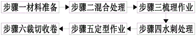
In order to achieve the purpose, the invention adopts the following technical scheme to realize the purpose: a non-woven fabric production and processing technology mainly comprises the following steps:
preparing materials, namely preparing fiber raw materials and polyester fibers;
step two, mixing treatment, namely mixing the fiber raw material prepared in the step one with polyester fibers to obtain non-woven fabric fibers;
step three, carding operation, namely carding operation is carried out on the non-woven fabric fibers obtained in the step two to obtain a non-woven fabric fiber net;
step four, carrying out spunlace treatment, namely carrying out spunlace treatment on the non-woven fabric fiber web obtained in the step three, and drying the spunlaced cloth to obtain dry spunlaced cloth;
step five, performing shaping operation, namely performing shaping operation on the dried spunlace fabric obtained in the step four to obtain shaped spunlace fabric;
and step six, cutting and rolling, namely conveying the shaped spunlace fabric obtained in the step five into a non-woven fabric rolling device to roll the spunlace fabric, and packaging the rolled finished spunlace fabric to obtain the packaged finished spunlace fabric.
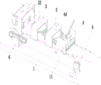
The non-woven fabric winding equipment used in the steps comprises a bottom plate, a cutting device, a smoothing device, a cutting device, a winding device and a power mechanism, wherein the bottom plate is symmetrically provided with a supporting plate from front to back, the cutting device is respectively arranged from the left end to the right end of the supporting plate, the smoothing device, the cutting device and the winding device are arranged on the supporting plate, and the power mechanism is arranged on the left side of the outer wall of the front end of the supporting plate positioned at the front end of the bottom plate.
The cutting device comprises a cutting frame, a telescopic cylinder, a cutting round rod, a cutting round roller, a lower pressing plate, a first motor, a bidirectional threaded rod, a sliding plate, a rotary round rod and a rotary cutter, wherein the cutting round rod is installed between the inner walls of the front end and the rear end of the left side of the supporting plate through a bearing, the cutting round roller is installed in the middle of the cutting round rod, the cutting frame is installed on the left side of the upper end of the supporting plate, the telescopic cylinder is installed at the upper end of the cutting frame, the output end of the telescopic cylinder penetrates through the cutting frame to be installed with the lower pressing plate, a feeding mechanism is installed at the left end of the lower pressing plate, sliding grooves are formed in the lower pressing plate, the sliding plates are symmetrically installed in the sliding grooves in the front-back mode through sliding fit, a transmission threaded groove is formed in each sliding plate, the first motor is installed, and the two-way threaded rod is installed in the transmission thread groove through screw-thread fit's mode, and the sliding plate lower extreme has been seted up and has been cut the cut groove, cuts and installs rotatory round bar through the bearing between the both ends inner wall around the cut groove, and rotatory round bar mid-mounting has the rotary cutter, can carry out stable operation of cutting to the deckle edge of non-woven fabrics.
The smoothing device comprises a transmission round rod, a transmission round roller, a conveying belt, a U-shaped plate, a pressing cylinder, a clamping plate, a U-shaped rod, a clamping block, a long rod, a U-face rod, a smoothing round roller, a sliding round rod, a driven disc, a connecting round rod, a rotating gear, a positioning block, a pushing cylinder and a pushing rack, wherein the transmission round rod is symmetrically arranged between the inner walls of the front end and the rear end of the middle part of the supporting plate through a bearing, the transmission round roller is arranged in the middle part of the transmission round rod, the transmission round rollers are connected through the conveying belt, the U-shaped plate is symmetrically arranged in the middle part of the upper end of the supporting plate, clamping grooves are formed in the inner walls of the front end and the rear end of the U-shaped plate, the clamping grooves are connected through the clamping plate, the clamping plate is arranged in the clamping grooves in a sliding fit manner, straight grooves are formed, a propelling groove is arranged on the long rod, a U-shaped rod is arranged at the lower end of the clamping block, a smoothing round rod is arranged between the inner walls of the left end and the right end of the U-shaped rod through a bearing, a smoothing round roller is arranged in the middle of the smoothing round rod, a U-shaped rod is arranged at the upper end of the clamping plate, a connecting round rod is arranged in the middle of the U-shaped rod in a rotation fit mode, a driven disc is arranged at the lower end of the connecting round rod, sliding round rods are eccentrically and symmetrically arranged at the lower end of the driven disc, the sliding round rods are arranged in the propelling groove in a sliding fit mode, a rotating gear is arranged at the upper end of the connecting round rod, a positioning block is arranged at the right side of the middle of the upper end of the U-shaped rod, a positioning groove is arranged on the positioning block, a propelling rack is arranged in the positioning, the push down cylinder is installed to U form board upper end, and the push down cylinder output passes U form board and connects on U form pole, through pacifying the round bar and pacifying the relative motion between the round roller for it can pacify the operation to smooth the round roller to the non-woven fabrics when the rolling, makes the phenomenon that can not take place the fold behind the non-woven fabrics rolling.
The cutting device comprises a flat plate, a U-shaped frame, a supporting block, a positioning round rod, a rotating rod, a clamping round rod, a downward pressing round plate, a return spring, a cutting knife, a straight plate, a T-shaped round rod, a positioning spring, a strip plate and a rubber plate, wherein the flat plate is arranged between the inner walls of the right side of the supporting plate, the U-shaped frame is arranged at the position of the flat plate at the upper end of the supporting plate, a through groove is formed in the middle of the U-shaped frame, through holes are formed in the middle parts of the inner walls of the upper end and the lower end of the through groove, the clamping round rod is arranged in the through hole in a sliding fit mode, the downward pressing round plate is arranged at the upper side of the middle part of the clamping round rod in the through groove, the return spring is sleeved in the through groove on the clamping round rod, the upper end of the return spring is connected to the downward pressing round plate, the, install T form round bar through sliding fit's mode in the perforation, be connected through rectangular board between the T form round bar lower extreme, the rubber slab is installed to the rectangular board lower extreme, the cover is equipped with positioning spring on the T form round bar, the positioning spring upper end is connected on straight board, the positioning spring lower extreme is connected on rectangular board, U type frame upper end front side bilateral symmetry installs the supporting shoe, install the location round bar between the inner wall at both ends about the supporting shoe, install the rotary rod through normal running fit's mode on the location round bar, can carry out stable operation of cutting to the non-woven fabrics.
As a preferred technical scheme of the invention, the feeding mechanism comprises a top plate, a T-shaped round rod, a butting spring, a U-shaped plate, a feeding round rod, a feeding round roller, a driven round rod and a driven round roller, lower clamp plate left end outer wall on install the roof, the smooth hole has evenly been seted up from front end to rear end on the roof, install T type round bar through sliding fit's mode in the smooth hole, T type round bar lower extreme is connected through the U template, the cover is equipped with and supports tight spring on the T type round bar, support tight spring upper end and connect on the roof, support tight spring lower extreme and connect on the U template, install the feeding round bar through the bearing between the inner wall at both ends around the U template, feeding round bar mid-mounting has the feeding round roller, it installs driven round bar through the bearing to lie in feeding round roller downside between the backup pad inner wall, driven round bar mid-mounting has driven round roller, provide stable transport environment for the transport of non-woven fabrics.
As a preferred technical scheme, the power mechanism comprises an L-shaped plate, a second motor, a power gear and an internal tooth belt, the front ends of the transmission round rod, the driven round rod and the cutting round rod penetrate through a supporting plate positioned at the front end of the bottom plate to be provided with the power gear, the power gears are connected through the internal tooth belt, the L-shaped plate is arranged on the outer wall of the front end of the supporting plate positioned at the front end of the bottom plate, the second motor is arranged on the L-shaped plate, and the output end of the second motor is connected to the power gear positioned at the front end of the cutting round rod, so that stable power is provided for conveying non-woven fabrics.
According to a preferred technical scheme, the winding device comprises a round winding rod, a square insertion rod, a round winding roller, a butt joint cylinder, a square plate and a third motor, the round winding rod is mounted on the right side of a supporting plate located at the rear end of a bottom plate in a rotating fit mode, the square insertion rod is mounted at the front end of the round winding rod, a flat groove is formed in the front side of the right end of the bottom plate, the square plate is mounted in the flat groove in a sliding fit mode, the butt joint cylinder is mounted on the front side of the flat groove on the bottom plate, the output end of the butt joint cylinder is connected to the outer wall of the square plate, the third motor is mounted on the square plate, the output end of the third motor penetrates through the square plate and is mounted with the square insertion rod, grooves are symmetrically formed in the outer walls of the front end and the rear end of the round winding roller, the square insertion rod.
As a preferable technical scheme of the invention, the upper end of the clamping round rod is hemispherical, a convex surface is arranged at the contact position of the middle part of the lower side of the rotating rod and the clamping round rod, and the hemispherical surface on the clamping round rod and the convex surface on the rotating rod are matched with each other for use, so that the rotating rod can better drive the clamping round rod to move.
As a preferable technical scheme, a material guiding round rod is arranged between the inner walls of the front end and the rear end of the right end of the supporting plate through bearings, and a material guiding round roller is arranged in the middle of the material guiding round rod, so that a stable conveying environment is provided for winding of non-woven fabrics.
The invention has the beneficial effects that:
1. the invention can solve the following problems existing in the rolling of the existing non-woven fabric, a, the traditional non-woven fabric can not cut the rough edges formed by the non-woven fabric when rolling, and the rough edges of the non-woven fabric need to be cut by using a tool manually after the non-woven fabric is rolled, so that the rolling production quality of the non-woven fabric is reduced; b, current non-woven fabrics rolling equipment when the rolling, the phenomenon of fold often takes place, needs the manual work to loosen the back and carries out the rolling operation again, has increased staff's work load, has reduced the rolling quality and the efficiency of non-woven fabrics.
2. The cutting device designed by the invention drives the rotary cutters to move to proper spacing positions through the sliding plate, and the rotary cutters can cut burrs of the non-woven fabric while the non-woven fabric is wound, so that the production quality of the non-woven fabric is improved, and the labor intensity of workers is reduced.
3. According to the smoothing device designed by the invention, the smoothing round roller can perform smoothing operation on the non-woven fabric during rolling through the opposite movement between the smoothing round rod and the smoothing round roller, so that the non-woven fabric is not wrinkled after being rolled, and the rolling quality of the non-woven fabric is improved.
4. The cutting device provided by the invention can be used for positioning the non-woven fabric through the strip plate and the rubber plate and cutting the non-woven fabric through the cutting knife, so that the winding efficiency of the non-woven fabric is improved.
Drawings
The invention is further illustrated with reference to the following figures and examples.
FIG. 1 is a flow chart of the operation of the present invention;
FIG. 2 is a schematic structural view of the non-woven fabric winding device of the present invention;
FIG. 3 is a partial cross-sectional view of FIG. 2 of the present invention;
FIG. 4 is a schematic view of a partial structure of the cutting device of the present invention;
FIG. 5 is a partial cross-sectional view of the invention of FIG. 4;
FIG. 6 is a schematic view of a partial structure of the pacifying device of the present invention;
FIG. 7 is a partial cross-sectional view of a pacifying device of the present invention;
FIG. 8 is a schematic view of a portion of the cutting device of the present invention;
figure 9 is a partial cross-sectional view of the winding device of the invention.
Detailed Description
The embodiments of the invention will be described in detail below with reference to the drawings, but the invention can be implemented in many different ways as defined and covered by the claims.
As shown in fig. 1 to 9, a non-woven fabric production process mainly includes the following steps:
preparing materials, namely preparing fiber raw materials and polyester fibers;
step two, mixing treatment, namely mixing the fiber raw material prepared in the step one with polyester fibers to obtain non-woven fabric fibers;
step three, carding operation, namely carding operation is carried out on the non-woven fabric fibers obtained in the step two to obtain a non-woven fabric fiber net;
step four, carrying out spunlace treatment, namely carrying out spunlace treatment on the non-woven fabric fiber web obtained in the step three, and drying the spunlaced cloth to obtain dry spunlaced cloth;
step five, performing shaping operation, namely performing shaping operation on the dried spunlace fabric obtained in the step four to obtain shaped spunlace fabric;
cutting and winding, namely conveying the shaped spunlace fabric obtained in the step five into a non-woven fabric winding device to wind the spunlace fabric, and packaging the wound finished spunlace fabric to obtain a packaged finished spunlace fabric;
the non-woven fabric winding equipment used in the steps comprises a bottom plate 1, a cutting device 2, a smoothing device 3, a cutting device 4, a winding device 5 and a power mechanism 6, wherein the bottom plate 1 is symmetrically provided with a supporting plate 11 in front and back, the cutting device 2 is respectively arranged from the left end to the right end on the supporting plate 11, the smoothing device 3, the cutting device 4 and the winding device 5 are arranged, and the power mechanism 6 is arranged on the left side of the outer wall of the front end of the supporting plate 11, which is positioned at the front end of the bottom plate 1.
A material guiding round rod 12 is arranged between the inner walls of the front end and the rear end of the right end of the supporting plate 11 through bearings, and a material guiding round roller 13 is arranged in the middle of the material guiding round rod 12.
During specific work, the manual work is established the recess cover on the rolling circle roller 53 on the square inserted bar 52 that is located rolling circle bar 51, the butt joint cylinder 54 drives the motion of square plate 55, square plate 55 drives the motion of No. three motors 56, No. three motors 56 drive square inserted bar 52 and insert in the recess of front end on the rolling circle roller 53, the manual work is drawn the spunlace cloth and is passed cutting device 2, smooth device 3, cutting device 4 and guide circle roller 13 are connected to on the rolling circle roller 53, No. three motors 56 drive square inserted bar 52 and rotate, square inserted bar 52 drives rolling circle roller 53 and rotates, make rolling circle roller 53 carry out the rolling operation to the spunlace cloth.
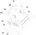
The cutting device 2 comprises a cutting frame 2a, a telescopic cylinder 2b, a cutting round rod 2c, a cutting round roller 2d, a lower press plate 2e, a first motor 2f, a bidirectional threaded rod 2g, a sliding plate 2h, a rotating round rod 2i and a rotary cutter 2j, wherein the cutting round rod 2c is arranged between the inner walls of the front end and the rear end of the left side of the supporting plate 11 through a bearing, the cutting round roller 2d is arranged in the middle of the cutting round rod 2c, the cutting frame 2a is arranged on the left side of the upper end of the supporting plate 11, the telescopic cylinder 2b is arranged on the upper end of the cutting frame 2a, the output end of the telescopic cylinder 2b penetrates through the cutting frame 2a to be provided with the lower press plate 2e, the left end of the lower press plate 2e is provided with a feeding mechanism 22, the lower press plate 2e is provided with a sliding chute, the sliding plates 2h are symmetrically arranged in the sliding fit manner, the sliding plate 2h is provided with, no. one motor 2f output passes holding down plate 2e and installs two-way threaded rod 2g, and two-way threaded rod 2g front end passes through the bearing and installs on spout front end inner wall, and two-way threaded rod 2g installs in the transmission thread groove through screw-thread fit's mode, and the sliding plate 2h lower extreme has been seted up and has been cut the cut groove, cuts and installs rotatory round bar 2i between the both ends inner wall around the cut groove through the bearing, and rotatory round bar 2i mid-mounting has rotary cutter 2 j.
The feeding mechanism 22 comprises a top plate 221, a T-shaped round bar 222, a resisting spring 223, a U-shaped plate 224, a feeding round bar 225, a feeding round roller 226, a driven round bar 227 and a driven round roller 228, the outer wall of the left end of the lower press plate 2e is provided with a top plate 221, a slide hole is uniformly formed in the top plate 221 from the front end to the rear end, a T-shaped round rod 222 is installed in the slide hole in a sliding fit mode, the lower end of the T-shaped round rod 222 is connected with a U-shaped plate 224, a propping spring 223 is sleeved on the T-shaped round rod 222, the upper end of the propping spring 223 is connected onto the top plate 221, the lower end of the propping spring 223 is connected onto the U-shaped plate 224, a feeding round rod 225 is installed between the inner walls of the front end and the rear end of the U-shaped plate 224 through a bearing, the feeding round rod 225 is provided with a feeding round roller 226 in the middle, a driven round rod 227 is installed on the lower side of the feeding round roller 226 between the inner.
When the device works, after the spunlace is pulled to pass through the lower sides of the feeding round roller 226 and the rotary cutter 2j, the first motor 2f drives the two-way threaded rod 2g to rotate, the two-way threaded rod 2g drives the sliding plate 2h to move in a thread matching mode, the sliding plate 2h drives the rotary round rod 2i to move, the rotary round rod 2i drives the rotary cutter 2j to move to a proper cutting position, the telescopic cylinder 2b drives the lower pressing plate 2e to move towards the lower end, the lower pressing plate 2e drives the sliding plate 2h to move towards the lower end, the sliding plate 2h drives the rotary cutter 2j to move towards the lower end through the rotary round rod 2i, so that the rotary cutter 2j tightly presses the spunlace on the cutting round roller 2d, meanwhile, the lower pressing plate 2e drives the top plate 221 to move towards the lower end, the top plate 221 drives the T-shaped round rod 222 to move towards the lower end, the T-shaped round rod 222 drives the U-shaped plate 224 to move towards the lower end, and the U, the feeding round bar 225 drives the feeding round roller 226 to move towards the lower end, so that the feeding round roller 226 tightly supports the spunlace fabric on the driven round roller 228, and when the spunlace fabric is rolled, the rotary cutter 2j cuts rough edges on the front side and the rear side of the spunlace fabric.
The flattening device 3 comprises a transmission round rod 3a, a transmission round roller 3b, a conveyer belt 3c, a U-shaped plate 3d, a pressing cylinder 3e, a clamping plate 3f, a U-shaped rod 3g, a clamping block 3h, a long rod 3i, a U-shaped rod 3j, a flattening round rod 3k, a flattening round roller 3l, a sliding round rod 3m, a driven disc 3n, a connecting round rod 3o, a rotating gear 3p, a positioning block 3q, a pushing cylinder 3r and a pushing rack 3s, wherein the transmission round rods 3a are symmetrically arranged between the inner walls of the front end and the rear end of the middle part of the supporting plate 11 through bearings, the transmission round roller 3b is arranged in the middle part of the transmission round rod 3a, the transmission round rollers 3b are connected through the conveyer belt 3c, the U-shaped plate 3d is symmetrically arranged between the left end and the right end of the middle part of the upper end of the supporting plate 11, the inner walls of the front end and the rear end, a clamping plate 3f is arranged in the clamping groove in a sliding fit manner, a straight groove is formed in the clamping plate 3f, clamping blocks 3h are symmetrically arranged in the straight groove in a front-back manner in a sliding fit manner, a long rod 3i is arranged at the upper end of each clamping block 3h, a pushing groove is formed in each long rod 3i, a U-shaped rod 3j is arranged at the lower end of each clamping block 3h, a smoothing round rod 3k is arranged between the inner walls of the left end and the right end of each U-shaped rod 3j through a bearing, a smoothing round roller 3l is arranged in the middle of each smoothing round rod 3k, a U-shaped rod 3g is arranged at the upper end of each clamping plate 3f, a connecting round rod 3o is arranged in the middle of each U-shaped rod 3g in a rotating fit manner, a driven disc 3n is arranged at the lower end of each connecting round rod 3o, sliding round rods 3m are eccentrically and symmetrically arranged in the pushing grooves in a sliding fit manner, a, locating piece 3q is installed on U form pole 3g upper end middle part right side, the constant head tank has been seted up on locating piece 3q, install through sliding fit's mode in the constant head tank and impel rack 3s, and impel and mutually support between rack 3s and the rotating gear 3p and use, install on the U form pole 3g and impel cylinder 3r, impel cylinder 3r output and connect on impelling rack 3s, the air cylinder 3e that pushes down is installed to U form board 3d upper end, the air cylinder 3e output that pushes down passes U form board 3d and connects on U form pole 3 g.
When the machine works, after the spunlace is drawn to penetrate through the lower side of the smoothing round roller 3l, the second motor 62 drives the power gear 63 to rotate, the power gear 63 is driven by the internal tooth belt 64, so that the power gear 63 drives the transmission round rod 3a, the driven round rod 227 and the cutting round rod 2c to rotate, the driven round rod 227 drives the driven round roller 228 to rotate, better conveying operation is carried out on the spunlace, meanwhile, the cutting round rod 2c drives the cutting round roller 2d to rotate, so that the rotary cutter 2j can completely cut burrs on the front side and the rear side of the spunlace, meanwhile, the transmission round rod 3a drives the transmission round roller 3b to rotate, the transmission round roller 3b drives the conveyer belt 3c to rotate, the conveyer belt 3c carries out stable conveying operation on the spunlace, when the spunlace moves to the lower end of the U-shaped plate 3d at the upper left end of the supporting plate 11, the pressing cylinder 3e drives the U-shaped rod 3g to move towards the lower end, the U-shaped rod 3g drives the clamping plate 3f to move towards the lower end, the clamping plate 3f drives the clamping block 3h to move towards the lower end, the clamping block 3h drives the U-shaped rod 3j to move towards the lower end, the U-shaped rod 3j drives the smoothing round rod 3k to move towards the lower end, the smoothing round rod 3k drives the smoothing round roller 3l to move towards the lower end, the smoothing round roller 3l abuts against the spunlace on the conveying belt 3c, the propulsion cylinder 3r drives the propulsion rack 3s to move, the propulsion rack 3s drives the rotating gear 3p to rotate for a certain angle in a gear matching mode, the rotating gear 3p drives the connecting round rod 3o to rotate, the connecting round rod 3o drives the driven disc 3n to rotate, the driven disc 3n drives the sliding round rod 3n to rotate, the sliding round rod 3m slides in the propulsion groove on the long rod 3i, the sliding round rod 3m drives the long rod 3i to slide towards the front side and the back side, the long rod 3i drives the U-face rod 3j to slide towards the front side and the back side, the U-shaped surface rod 3j drives the smoothing round roller 3l to slide towards the front side and the rear side through the smoothing round rod 3k, so that the smoothing round roller 3l can smooth the spunlace cloth.
When the smoothing roller 3l moves to the front side and the rear side, the pressing cylinder 3e drives the U-shaped rod 3g to move upwards, the U-shaped rod 3g drives the clamping block 3h to move upwards through the clamping plate 3f, the clamping block 3h drives the smoothing roller 3k to move upwards through the U-shaped rod 3j, the smoothing roller 3l is driven by the smoothing roller 3k to move upwards to the initial position, the pushing cylinder 3r drives the pushing rack 3s to move, the pushing rack 3s drives the rotating gear 3p to rotate to the initial position through the gear matching mode, the rotating gear 3p drives the driven disc 3n to rotate through the connecting circular rod 3o, the driven disc 3n drives the sliding circular rod 3m to slide in the pushing groove on the long rod 3i, so that the sliding circular rod 3m drives the long rod 3i to move to the initial position, the long rod 3i drives the U-shaped rod 3j to move to the initial position through the clamping block 3h, the U-shaped rod 3j drives the smoothing circular roller 3l to move to the initial position through the smoothing circular rod 3k, and when the spunlace fabric moves to the lower end of the U-shaped plate 3d at the right end of the supporting plate 11, the movement is repeated, so that the spunlace fabric is always in a flat state when being wound.
The cutting device 4 comprises a flat plate 4a, a U-shaped frame 4b, a supporting block 4c, a positioning round rod 4d, a rotating rod 4e, a clamping round rod 4f, a pressing round plate 4g, a return spring 4h, a cutting knife 4i, a straight plate 4j, a T-shaped round rod 4k, a positioning spring 4l, a long strip plate 4m and a rubber plate 4n, wherein the flat plate 4a is arranged between the inner walls of the right side of the supporting plate 11, the U-shaped frame 4b is arranged at the position of the flat plate 4a at the upper end of the supporting plate 11, a through groove is formed in the middle of the U-shaped frame 4b, through holes are formed in the middle parts of the inner walls of the upper end and the lower end of the through groove, the clamping round rod 4f is arranged in the through groove in a sliding fit manner, the pressing round plate 4g is arranged at the upper side of the middle part of the clamping round rod 4f, the return spring, return spring 4h lower extreme is connected on leading to groove lower extreme inner wall, chucking round bar 4f lower extreme is installed and is cut sword 4i, cut and to install straight board 4j on the sword 4i left and right sides both ends outer wall symmetrically, the perforation has evenly been seted up from front end to rear end on the straight board 4j, install T form round bar 4k through sliding fit's mode in the perforation, be connected through rectangular slab 4m between the T form round bar 4k lower extreme, rubber slab 4n is installed to rectangular slab 4m lower extreme, the cover is equipped with positioning spring 4l on the T form round bar 4k, positioning spring 4l upper end is connected on straight board 4j, positioning spring 4l lower extreme is connected on rectangular slab 4m, supporting shoe 4c is installed to U type frame 4b upper end bilateral symmetry, install location round bar 4d between the inner wall at both ends about supporting shoe 4c, install rotary rod 4e through normal running fit's mode on the location round bar 4 d.
Chucking round bar 4f upper end be hemispherical, contact position department is provided with the convex surface on rotary rod 4e downside middle part and chucking round bar 4f, and mutually support between hemispherical on chucking round bar 4f and the convex surface on rotary rod 4e and use.
When the machine works specifically, after the winding operation of the winding round roller 53 on the spunlace fabric is completed, the rotating rod 4e is manually rotated, the rotating rod 4e rotates by taking the positioning round rod 4d as a circle center, so that the rotating rod 4e drives the clamping round rod 4f to slide towards the lower end, the clamping round rod 4f drives the downward pressing round plate 4g to move towards the lower end, the downward pressing round plate 4g drives the return spring 4h to move, and the return spring 4h is in a compression state, meanwhile, the clamping round rod 4f drives the cutting knife 4i to move towards the lower end, the cutting knife 4i drives the straight plate 4j to move towards the lower end, the straight plate 4 drives the long strip plate 4m and the rubber plate 4n to move towards the lower end through the T-shaped round rod 4k, so that the long strip plate 4m and the rubber plate 4n tightly support the spunlace fabric on the flat plate 4a, and the cutting knife 4i performs cutting operation on.
After the spunlace fabric is cut, the rolling round roller 53 is manually connected, the butt joint air cylinder 54 drives the square plate 55 to move, the square plate 55 drives the third motor 56 to move, the third motor 56 drives the square insertion rod 52 to move to the initial position, the rolling round roller 53 with the rolling completed is manually taken down, the rough edge roll and the spunlace fabric roll with the cutting completed are taken out, the groove sleeve on the rolling round roller 53 is manually sleeved on the square insertion rod 52 on the rolling round rod 51, the operations are repeated, and the spunlace fabric can be continuously rolled.
The foregoing illustrates and describes the principles, general features, and advantages of the present invention. It will be understood by those skilled in the art that the present invention is not limited to the embodiments described above, which are given by way of illustration of the principles of the present invention, and that various changes and modifications may be made without departing from the spirit and scope of the invention as defined by the appended claims. The scope of the invention is defined by the appended claims and equivalents thereof.
Claims (6)
1. A non-woven fabric production and processing technology is characterized in that: the method mainly comprises the following steps:
preparing materials, namely preparing fiber raw materials and polyester fibers;
step two, mixing treatment, namely mixing the fiber raw material prepared in the step one with polyester fibers to obtain non-woven fabric fibers;
step three, carding operation, namely carding operation is carried out on the non-woven fabric fibers obtained in the step two to obtain a non-woven fabric fiber net;
step four, carrying out spunlace treatment, namely carrying out spunlace treatment on the non-woven fabric fiber web obtained in the step three, and drying the spunlaced cloth to obtain dry spunlaced cloth;
step five, performing shaping operation, namely performing shaping operation on the dried spunlace fabric obtained in the step four to obtain shaped spunlace fabric;
cutting and winding, namely conveying the shaped spunlace fabric obtained in the step five into a non-woven fabric winding device to wind the spunlace fabric, and packaging the wound finished spunlace fabric to obtain a packaged finished spunlace fabric;
the non-woven fabric winding equipment used in the steps comprises a bottom plate (1), a cutting device (2), a smoothing device (3), a cutting device (4), a winding device (5) and a power mechanism (6), wherein supporting plates (11) are symmetrically arranged on the front and back of the bottom plate (1), the cutting device (2), the smoothing device (3), the cutting device (4) and the winding device (5) are respectively arranged on the supporting plates (11) from the left end to the right end, and the power mechanism (6) is arranged on the left side of the outer wall of the front end of the supporting plate (11) at the front end of the bottom plate (1);
the cutting device (2) comprises a cutting frame (2a), a telescopic cylinder (2b), a cutting round rod (2c), a cutting round roller (2d), a lower pressing plate (2e), a first motor (2f), a two-way threaded rod (2g), a sliding plate (2h), a rotating round rod (2i) and a rotary cutter (2j), wherein the cutting round rod (2c) is installed between the inner walls of the front end and the rear end of the left side of the supporting plate (11) through a bearing, the cutting round roller (2d) is installed in the middle of the cutting round rod (2c), the cutting frame (2a) is installed on the left side of the upper end of the supporting plate (11), the telescopic cylinder (2b) is installed on the upper end of the cutting frame (2a), the lower pressing plate (2e) is installed on the output end of the telescopic cylinder (2b) through the cutting frame (2a), a feeding mechanism (22) is installed on the left end of the, sliding plates (2h) are symmetrically arranged in the sliding grooves in a front-back mode in a sliding fit mode, transmission threaded grooves are formed in the sliding plates (2h), a first motor (2f) is arranged on the outer wall of the rear end of a lower pressing plate (2e), the output end of the first motor (2f) penetrates through the lower pressing plate (2e) to be provided with a bidirectional threaded rod (2g), the front end of the bidirectional threaded rod (2g) is arranged on the inner wall of the front end of the sliding groove through a bearing, the bidirectional threaded rod (2g) is arranged in the transmission threaded grooves in a threaded fit mode, the lower end of the sliding plate (2h) is provided with a cutting groove, a rotary round rod (2i) is arranged between the inner walls of the front end and the rear end of the cutting groove through a bearing;
the flattening device (3) comprises a transmission round rod (3a), a transmission round roller (3b), a conveying belt (3c), a U-shaped plate (3d), a pressing cylinder (3e), a clamping plate (3f), a U-shaped rod (3g), a clamping block (3h), a long rod (3i), a U-shaped rod (3j), a flattening round rod (3k), a flattening round roller (3l), a sliding round rod (3m), a driven disc (3n), a connecting round rod (3o), a rotating gear (3p), a positioning block (3q), a pushing cylinder (3r) and a pushing rack (3s), wherein the transmission round rod (3a) is arranged between the inner walls of the front end and the rear end of the middle part of the supporting plate (11) in a left-right symmetrical mode through a bearing, the transmission round roller (3b) is arranged in the middle part of the transmission round rod (3a), and the transmission round rollers (3b) are connected through the conveying belt (3c), the middle part of the upper end of the supporting plate (11) is bilaterally symmetrically provided with a U-shaped plate (3d), the inner walls of the front end and the rear end of the U-shaped plate (3d) are provided with clamping grooves, the clamping grooves are connected through clamping plates (3f), the clamping plates (3f) are arranged in the clamping grooves in a sliding fit mode, the clamping plates (3f) are provided with straight grooves, the straight grooves are symmetrically provided with clamping blocks (3h) in the front and rear direction in a sliding fit mode, the upper ends of the clamping blocks (3h) are provided with long rods (3i), the long rods (3i) are provided with pushing grooves, the lower ends of the clamping blocks (3h) are provided with U-shaped rods (3j), the inner walls of the left end and the right end of each U-shaped rod (3j) are provided with a smoothing round rod (3k) through bearings, the middle parts of the smoothing round rods (3k) are provided with smoothing round rollers (3l), the upper ends of the clamping plates (3f), the lower end of the connecting round rod (3o) is provided with a driven disc (3n), the lower end of the driven disc (3n) is eccentrically and symmetrically provided with sliding round rods (3m), a sliding round rod (3m) is arranged in the pushing groove in a sliding fit manner, a rotating gear (3p) is arranged at the upper end of the connecting round rod (3o), a positioning block (3q) is arranged at the right side of the middle part of the upper end of the U-shaped rod (3g), a positioning groove is formed in the positioning block (3q), a pushing rack (3s) is arranged in the positioning groove in a sliding fit manner, the propelling rack (3s) and the rotating gear (3p) are matched with each other for use, a propelling cylinder (3r) is mounted on the U-shaped rod (3g), the output end of the propelling cylinder (3r) is connected to the propelling rack (3s), a pressing cylinder (3e) is mounted at the upper end of the U-shaped plate (3d), and the output end of the pressing cylinder (3e) penetrates through the U-shaped plate (3d) to be connected to the U-shaped rod (3 g);
the cutting device (4) comprises a flat plate (4a), a U-shaped frame (4b), a supporting block (4c), a positioning round rod (4d), a rotating rod (4e), a clamping round rod (4f), a pressing round plate (4g), a return spring (4h), a cutting knife (4i), a straight plate (4j), a T-shaped round rod (4k), a positioning spring (4l), a long strip plate (4m) and a rubber plate (4n), wherein the flat plate (4a) is installed between the inner walls of the right side of the supporting plate (11), the U-shaped frame (4b) is installed at the position, located on the flat plate (4a), of the upper end of the supporting plate (11), a through groove is formed in the middle of the U-shaped frame (4b), through holes are formed in the middle parts of the inner walls of the upper end and the lower end of the through groove, the clamping round rod (4f) is installed in the through groove in a sliding fit mode, a return spring (4h) is sleeved in the through groove on the clamping round rod (4f), the upper end of the return spring (4h) is connected to the downward pressing round plate (4g), the lower end of the return spring (4h) is connected to the inner wall of the lower end of the through groove, a cutting knife (4i) is installed at the lower end of the clamping round rod (4f), straight plates (4j) are symmetrically installed on the outer walls of the left end and the right end of the cutting knife (4i), through holes are uniformly formed in the straight plates (4j) from the front end to the rear end, T-shaped round rods (4k) are installed in the through holes in a sliding fit mode, the lower ends of the T-shaped round rods (4k) are connected through long strip plates (4m), rubber plates (4n) are installed at the lower ends of the long strip plates (4m), positioning springs (4l) are sleeved on the T-shaped round rods (4k), the upper ends of the positioning springs (4l) are connected to the straight plates, supporting blocks (4c) are symmetrically installed on the left side and the right side of the front end of the upper end of the U-shaped frame (4b), a positioning round rod (4d) is installed between the inner walls of the left end and the right end of the supporting block (4c), and a rotating rod (4e) is installed on the positioning round rod (4d) in a rotating fit mode.
2. The non-woven fabric production and processing technology according to claim 1, characterized in that: the feeding mechanism (22) comprises a top plate (221), a T-shaped round rod (222), a pressing spring (223), a U-shaped plate (224), a feeding round rod (225), a feeding round roller (226), a driven round rod (227) and a driven round roller (228), wherein the top plate (221) is installed on the outer wall of the left end of a lower pressing plate (2e), slide holes are uniformly formed in the top plate (221) from the front end to the rear end, the T-shaped round rod (222) is installed in the slide holes in a sliding fit mode, the lower end of the T-shaped round rod (222) is connected through the U-shaped plate (224), the pressing spring (223) is sleeved on the T-shaped round rod (222), the upper end of the pressing spring (223) is connected to the top plate (221), the lower end of the pressing spring (223) is connected to the U-shaped plate (224), the feeding round rod (225) is installed between the inner walls of the front end and the rear end of the U-shaped plate (224) through a bearing, the, a driven round rod (227) is arranged between the inner walls of the supporting plates (11) and positioned on the lower side of the feeding round roller (226) through a bearing, and a driven round roller (228) is arranged in the middle of the driven round rod (227).
3. The non-woven fabric production and processing technology according to claim 2, characterized in that: power unit (6) include L template (61), No. two motor (62), power gear (63) and internal tooth belt (64), transmission round bar (3a), driven round bar (227) and cutting round bar (2c) front end all pass backup pad (11) that are located bottom plate (1) upper end and install power gear (63), be connected through internal tooth belt (64) between power gear (63), be located and install L template (61) on backup pad (11) front end outer wall of front end on bottom plate (1), install No. two motor (62) on L template (61), No. two motor (62) output is connected on power gear (63) that are located cutting round bar (2c) front end.
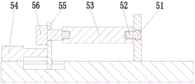
4. The non-woven fabric production and processing technology according to claim 1, characterized in that: the winding device (5) comprises a winding round rod (51), a square insertion rod (52), a winding round roller (53), a butt joint cylinder (54), a square plate (55) and a third motor (56), the winding round rod (51) is installed on the right side of a supporting plate (11) at the upper rear end of the base plate (1) in a rotating fit mode, the square insertion rod (52) is installed at the front end of the winding round rod (51), a flat groove is formed in the front side of the right end of the base plate (1), the square plate (55) is installed in the flat groove in a sliding fit mode, the butt joint cylinder (54) is installed on the front side of the flat groove on the base plate (1), the output end of the butt joint cylinder (54) is connected to the outer wall of the square plate (55), the third motor (56) is installed on the square plate (55), the output end of the third motor (56) penetrates through the square plate (55) to install the square insertion rod (52), grooves are symmetrically formed in the, and the square inserted bar (52) is arranged in the groove in a sliding fit mode.
5. The non-woven fabric production and processing technology according to claim 1, characterized in that: chucking round bar (4f) upper end be hemispherical, contact position department is provided with the convex surface on rotary rod (4e) downside middle part and chucking round bar (4f), and mutually support between the convex surface on hemispherical and rotary rod (4e) on chucking round bar (4f) and use.
6. The non-woven fabric production and processing technology according to claim 1, characterized in that: the inner walls of the front end and the rear end of the right end of the supporting plate (11) are provided with a material guiding round rod (12) through bearings, and the middle of the material guiding round rod (12) is provided with a material guiding round roller (13).
Priority Applications (1)
| Application Number | Priority Date | Filing Date | Title |
|---|---|---|---|
| CN202110297890.7A CN113060579A (en) | 2021-03-19 | 2021-03-19 | Non-woven fabric production and processing technology |
Applications Claiming Priority (1)
| Application Number | Priority Date | Filing Date | Title |
|---|---|---|---|
| CN202110297890.7A CN113060579A (en) | 2021-03-19 | 2021-03-19 | Non-woven fabric production and processing technology |
Publications (1)
| Publication Number | Publication Date |
|---|---|
| CN113060579A true CN113060579A (en) | 2021-07-02 |
Family
ID=76562550
Family Applications (1)
| Application Number | Title | Priority Date | Filing Date |
|---|---|---|---|
| CN202110297890.7A Withdrawn CN113060579A (en) | 2021-03-19 | 2021-03-19 | Non-woven fabric production and processing technology |
Country Status (1)
| Country | Link |
|---|---|
| CN (1) | CN113060579A (en) |
Cited By (3)
| Publication number | Priority date | Publication date | Assignee | Title |
|---|---|---|---|---|
| CN113942287A (en) * | 2021-10-18 | 2022-01-18 | 河北旭开宇科技有限公司 | Equipment for manufacturing sterilization mask cloth capable of releasing negative ions |
| CN114348706A (en) * | 2022-02-24 | 2022-04-15 | 安徽勇跃包装材料有限公司 | Automatic winding device for adhesive tape production |
| CN114671292A (en) * | 2022-04-19 | 2022-06-28 | 南通锦琪合纤有限公司 | Composite fiber processing is with having conveyer that edge anticurl was handled |
-
2021
- 2021-03-19 CN CN202110297890.7A patent/CN113060579A/en not_active Withdrawn
Cited By (4)
| Publication number | Priority date | Publication date | Assignee | Title |
|---|---|---|---|---|
| CN113942287A (en) * | 2021-10-18 | 2022-01-18 | 河北旭开宇科技有限公司 | Equipment for manufacturing sterilization mask cloth capable of releasing negative ions |
| CN114348706A (en) * | 2022-02-24 | 2022-04-15 | 安徽勇跃包装材料有限公司 | Automatic winding device for adhesive tape production |
| CN114671292A (en) * | 2022-04-19 | 2022-06-28 | 南通锦琪合纤有限公司 | Composite fiber processing is with having conveyer that edge anticurl was handled |
| CN114671292B (en) * | 2022-04-19 | 2023-09-26 | 南通锦琪合纤有限公司 | Conveying device with edge anti-rolling treatment for composite fiber processing |
Similar Documents
| Publication | Publication Date | Title |
|---|---|---|
| CN113060579A (en) | Non-woven fabric production and processing technology | |
| CN112962295B (en) | Cutting mechanism of non-woven fabric for mask machine | |
| CN212688475U (en) | Device is tailor with end of a thread to fabrics processing | |
| CN113135012A (en) | Manufacturing and processing technology of sodium bentonite waterproof blanket | |
| CN110499588B (en) | Ultrasonic quilt machine | |
| CN202044218U (en) | Wound mop bundling machine | |
| CN210260528U (en) | Rolling machine | |
| CN108360162B (en) | Pillowcase machine | |
| CN215248396U (en) | Coiling mechanism is used in non-woven fabrics processing | |
| CN215209918U (en) | Automatic binding device for clothing production | |
| CN209555622U (en) | A kind of non-woven fabric process units suitable for interior leather for automobiles production | |
| CN210801837U (en) | Chemical fiber cloth production is with hanging drying device | |
| CN113752670A (en) | Film laminating device and method for polystyrene decorative strip | |
| CN210177251U (en) | Fabric cutting and collecting device and full-automatic fabric cutting and sewing system | |
| CN112981737A (en) | Automatic binding device for clothing production | |
| CN214878945U (en) | Coiling mechanism is used in processing of non-woven fabrics surface fabric | |
| CN216189652U (en) | Semi-automatic three-dimensional granny rag device | |
| CN106078819B (en) | Device is cut and removed in sheet material side after shaping | |
| CN216471252U (en) | Cloth unwinding device with stop function | |
| CN217948588U (en) | Cloth strip cutting device | |
| CN220826086U (en) | Rolling type wallpaper cutting device | |
| CN217861928U (en) | Guide rail wheel type blank cutting equipment suitable for ceramic plate machining | |
| CN214988980U (en) | Fishing net roller support frame for fishing net production | |
| CN218171589U (en) | Bag making and packaging machine | |
| CN212445596U (en) | Grinding wheel mesh slicing machine capable of efficiently forming and separating |
Legal Events
| Date | Code | Title | Description |
|---|---|---|---|
| PB01 | Publication | ||
| PB01 | Publication | ||
| SE01 | Entry into force of request for substantive examination | ||
| SE01 | Entry into force of request for substantive examination | ||
| WW01 | Invention patent application withdrawn after publication | ||
| WW01 | Invention patent application withdrawn after publication |
Application publication date: 20210702 |
|
| DD01 | Delivery of document by public notice | ||
| DD01 | Delivery of document by public notice |
Addressee: Yiwu Heming Textile Technology Co.,Ltd. Document name: Refund Approval Notice |