CN216189652U - Semi-automatic three-dimensional granny rag device - Google Patents
Semi-automatic three-dimensional granny rag device Download PDFInfo
- Publication number
- CN216189652U CN216189652U CN202122756811.2U CN202122756811U CN216189652U CN 216189652 U CN216189652 U CN 216189652U CN 202122756811 U CN202122756811 U CN 202122756811U CN 216189652 U CN216189652 U CN 216189652U
- Authority
- CN
- China
- Prior art keywords
- cloth
- roller
- belt wheel
- belt
- pressing roller
- Prior art date
- Legal status (The legal status is an assumption and is not a legal conclusion. Google has not performed a legal analysis and makes no representation as to the accuracy of the status listed.)
- Active
Links
Images


Abstract
The utility model relates to the technical field of textile equipment, in particular to a semi-automatic three-dimensional cloth pulling device; the motor is fixedly connected with the supporting component, the rotating shaft is connected with the motor in a rotating mode, the belt wheel is connected with the rotating shaft in a rotating mode, the belt is connected with the belt wheel in a sliding mode, the belt wheel is connected with the belt in a sliding mode, the lower pressing roller is fixedly connected with the belt wheel, the main gear is fixedly connected with the lower pressing roller, the auxiliary gear is connected with the main gear in a rotating mode, the upper pressing roller is fixedly connected with the auxiliary gear, the motor outputs power, the rotation enables the belt wheel to rotate, the belt wheel to start to rotate, the lower pressing roller drives the main gear to rotate, the main gear drives the auxiliary gear to rotate, the auxiliary gear drives the upper pressing roller to rotate, the lower pressing roller and the upper pressing roller rotate in the opposite direction, cloth in the cloth drawing process can be flattened, and the problem that wrinkles or air bubbles are generated in the cloth drawing process of existing equipment is solved.
Description
Technical Field
The utility model relates to the technical field of textile equipment, in particular to a semi-automatic three-dimensional cloth pulling device.
Background
A cloth spreading machine, which is a machine for manufacturing cloth appearing in the early 90 s of the last century. Since most of flexible materials are produced and transported in rolls, an important process is to change rolled materials into a multi-layer planar state for convenient cutting in a user factory.
At present, prior art (CN205739707U) discloses an automatic side cut device of granny rag machine, be connected with the cutter on the side cut motor, the horizontal bottom plate of angle bar frame is located below the side cut motor base and connects into an organic whole, the perpendicular curb plate of angle bar frame is fixed on the frame wall inside wall of the last frame on one side of the granny rag machine, the side cut motor is located the slide platform top behind the granny rag machine front column cylinder, there is the interval between angle bar frame horizontal bottom surface and the slide platform upper surface, the slide platform is just having a penetrating slide straight flute to the cutter position, the cutter bottom imbeds in the slide straight flute. When the cloth is stretched by the cloth stretcher, the edge of the cloth is automatically cut by the cloth stretcher, so that the edge cutting is automatically performed by a machine, the edge cutting is neat and consistent, and the edge-aligning effect of the cloth stretcher is improved.
However, when the above method is adopted, wrinkles or bubbles are generated in the cloth stretching process, which affects the production efficiency.
SUMMERY OF THE UTILITY MODEL
The utility model aims to provide a semi-automatic three-dimensional cloth spreading device, and aims to solve the problem that wrinkles are generated in the cloth spreading process of the existing equipment.
In order to achieve the purpose, the utility model provides a semi-automatic three-dimensional cloth spreading device which comprises a support component, a cloth pressing component and a discharging component, wherein the cloth pressing component comprises a motor, a rotating shaft, a belt wheel, a belt wheel, a lower pressing roller, a gear and an upper pressing roller, the motor is fixedly connected with the support component, the motor is positioned on one side of the support component, the rotating shaft is rotatably connected with the motor, the rotating shaft is positioned on one side of the motor, the belt wheel is rotatably connected with the rotating shaft, the belt wheel is positioned on one side of the rotating shaft far away from the motor, the belt is slidably connected with the belt wheel, the belt is positioned on the top of the belt wheel, the belt wheel is slidably connected with the belt, the belt wheel is positioned on one side of the belt far away from the belt wheel, and the lower pressing roller is fixedly connected with the belt wheel, the lower compression roller is located one side of the belt pulley, the gear comprises a main gear and an auxiliary gear, the main gear is fixedly connected with the lower compression roller, the main gear is located on one side, away from the belt pulley, of the lower compression roller, the auxiliary gear is rotationally connected with the main gear, the auxiliary gear is located on one side of the main gear, the upper compression roller is fixedly connected with the auxiliary gear, and the upper compression roller is located on one side of the auxiliary gear.
The cloth pressing component further comprises a protective cover, the protective cover is fixedly connected with the supporting component, and the protective cover is located on one side of the supporting component.
The protective cover can prevent some sundries from falling into the gear or the belt to cause the device to be in operation failure.
The cloth pressing assembly comprises a lower pressing roller and an upper pressing roller, wherein the cloth pressing assembly further comprises two rubber pads, the two rubber pads are fixedly connected with the lower pressing roller and the upper pressing roller respectively, and the two rubber pads are located on one sides of the lower pressing roller and the upper pressing roller respectively.
The two rubber pads can ensure that the lower pressing roller and the upper pressing roller can not damage cloth in the long-time cloth pressing process.
The cloth feeding assembly comprises a cloth feeding roller and a cloth collecting roller, the cloth feeding roller is connected with the supporting assembly in a rotating mode, the cloth feeding roller is located on one side of the supporting assembly, the cloth collecting roller is connected with the supporting assembly in a rotating mode, and the cloth collecting roller is located on one side, away from the supporting assembly, of the cloth feeding roller.
Rotate put the cloth roller, can convey the cloth to the compress subassembly flattens, rotates the cloth roller, can be steady collect the cloth that accomplishes flattening.
Wherein, the blowing subassembly still includes the dwang, the dwang is two, two dwangs respectively with put the cloth roller with the receipts cloth roller rotates to be connected, two dwangs are located put the cloth roller with one side of receipts cloth roller.
Rotate two dwang can drive put the cloth roller with the cloth roller rotates, can be more convenient put cloth or receive cloth.
The utility model relates to a semi-automatic three-dimensional cloth spreading device, which comprises a support component, a cloth pressing component and a discharging component, wherein the cloth pressing component comprises a motor, a rotating shaft, a belt wheel, a belt wheel, a lower pressing roller, a gear and an upper pressing roller, the motor is fixedly connected with the support component, the motor is positioned on one side of the support component, the rotating shaft is rotatably connected with the motor, the rotating shaft is positioned on one side of the motor, the rotating shaft is driven to rotate by the output power of the motor, the belt wheel is rotatably connected with the rotating shaft, the belt wheel is positioned on one side of the rotating shaft far away from the motor, the belt is slidably connected with the belt wheel, the belt is positioned on the top of the belt wheel, the belt wheel is slidably connected with the belt, the belt wheel is positioned on one side of the belt far away from the belt wheel, and the rotation of the rotating shaft drives the belt wheel to rotate, the belt wheel rotates to drive the belt to slide on the belt wheel, the belt slides to drive the belt wheel to rotate, the lower pressing roller is fixedly connected with the belt wheel, the lower pressing roller is positioned on one side of the belt wheel, the belt wheel rotates to enable the lower pressing roller to rotate, the gear comprises a main gear and a secondary gear, the main gear is fixedly connected with the lower pressing roller, the main gear is positioned on one side of the lower pressing roller, which is far away from the belt wheel, the secondary gear is rotatably connected with the main gear, the secondary gear is positioned on one side of the main gear, the lower pressing roller rotates to drive the main gear to rotate, the secondary gear can be driven to rotate after the main gear rotates, the main gear and the secondary gear rotate in opposite directions, and the upper pressing roller is fixedly connected with the secondary gear, go up the compression roller and be located one side of pinion rotates behind the pinion, can drive go up the compression roller and rotate, through motor output power, the rotation can rotate, drives the band pulley the belt pulley begins to rotate, through the belt pulley drives the compression roller rotates down, the compression roller drives down the master gear rotates, the master gear drives the pinion rotates, the pinion drives go up the compression roller and rotate, through down the compression roller with go up the relative direction rotation of compression roller, can flatten the cloth at the granny rag in-process, solve current equipment and produce the problem of fold or air drum at the granny rag in-process.
Drawings
In order to more clearly illustrate the embodiments of the present invention or the technical solutions in the prior art, the drawings used in the description of the embodiments or the prior art will be briefly described below, it is obvious that the drawings in the following description are only some embodiments of the present invention, and for those skilled in the art, other drawings can be obtained according to the drawings without creative efforts.
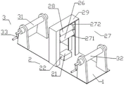
Fig. 1 is an isometric view of a semi-automatic stereoscopic granny rag device provided by the utility model.
Fig. 2 is a side view of a semi-automatic stereoscopic cloth spreading device provided by the utility model.
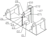
Fig. 3 is a structural diagram of a cloth pressing component of a semi-automatic three-dimensional cloth pulling device provided by the utility model.
Fig. 4 is a sectional view of a semi-automatic stereoscopic cloth spreading device provided by the utility model.
1-supporting component, 2-cloth pressing component, 3-discharging component, 21-motor, 22-rotating shaft, 23-belt wheel, 24-belt, 25-belt wheel, 26-lower pressing roller, 27-gear, 28-upper pressing roller, 29-protective cover, 210-rubber pad, 31-cloth discharging roller, 32-cloth collecting roller, 33-rotating rod, 271-main gear, 272-pinion.
Detailed Description
Reference will now be made in detail to embodiments of the present invention, examples of which are illustrated in the accompanying drawings, wherein like or similar reference numerals refer to the same or similar elements or elements having the same or similar function throughout. The embodiments described below with reference to the drawings are illustrative and intended to be illustrative of the utility model and are not to be construed as limiting the utility model.
In the description of the present invention, it is to be understood that the terms "length", "width", "upper", "lower", "front", "rear", "left", "right", "vertical", "horizontal", "top", "bottom", "inner", "outer", and the like, indicate orientations or positional relationships based on the orientations or positional relationships illustrated in the drawings, and are used merely for convenience in describing the present invention and for simplicity in description, and do not indicate or imply that the devices or elements referred to must have a particular orientation, be constructed in a particular orientation, and be operated, and thus, are not to be construed as limiting the present invention. Further, in the description of the present invention, "a plurality" means two or more unless specifically defined otherwise.
Referring to fig. 1 to 4, the present invention provides a semi-automatic three-dimensional cloth spreading device, which includes a support assembly 1, a cloth pressing assembly 2 and a cloth discharging assembly 3, wherein the cloth pressing assembly 2 includes a motor 21, a rotating shaft 22, a belt wheel 23, a belt 24, a belt pulley 25, a lower pressure roller 26, a gear 27 and an upper pressure roller 28, the motor 21 is fixedly connected with the support assembly 1, the motor 21 is located at one side of the support assembly 1, the rotating shaft 22 is rotatably connected with the motor 21, the rotating shaft 22 is located at one side of the motor 21, the belt wheel 23 is rotatably connected with the rotating shaft 22, the belt wheel 23 is located at one side of the rotating shaft 22 away from the motor 21, the belt 24 is slidably connected with the belt wheel 23, the belt 24 is located at the top of the belt wheel 23, the belt pulley 25 is slidably connected with the belt 24, the belt pulley 25 is located on one side of the belt 24 far away from the belt pulley 23, the lower pressing roller 26 is fixedly connected with the belt pulley 25, the lower pressing roller 26 is located on one side of the belt pulley 25, the gear 27 comprises a main gear 271 and a secondary gear 272, the main gear 271 is fixedly connected with the lower pressing roller 26, the main gear 271 is located on one side of the lower pressing roller 26 far away from the belt pulley 25, the secondary gear 272 is rotatably connected with the main gear 271, the secondary gear 272 is located on one side of the main gear 271, the upper pressing roller 28 is fixedly connected with the secondary gear 272, and the upper pressing roller 28 is located on one side of the secondary gear 272.
In this embodiment, the motor 21 is located on one side of the supporting component 1, the rotating shaft 22 is connected to the motor 21 in a rotating manner, the rotating shaft 22 is located on one side of the motor 21, the rotating shaft 22 is driven to rotate by the output power of the motor 21, the belt pulley 23 is connected to the rotating shaft 22 in a rotating manner, the belt pulley 23 is located on one side of the rotating shaft 22 away from the motor 21, the belt 24 is connected to the belt pulley 23 in a sliding manner, the belt 24 is located on the top of the belt pulley 23, the belt pulley 25 is connected to the belt 24 in a sliding manner, the belt pulley 25 is located on one side of the belt 24 away from the belt pulley 23, the rotating shaft 22 drives the belt pulley 23 to rotate, the belt pulley 23 rotates to drive the belt 24 to start sliding on the belt pulley 23, and after the belt 24 slides, the belt 25 is driven to start rotating, the lower pressing roller 26 is fixedly connected with the belt pulley 25, the lower pressing roller 26 is located at one side of the belt pulley 25, the belt pulley 25 is rotated, so that the lower pressing roller 26 starts to rotate, the gear 27 includes a main gear 271 and a sub-gear 272, the main gear 271 is fixedly connected with the lower pressing roller 26, the main gear 271 is located at one side of the lower pressing roller 26 away from the belt pulley 25, the sub-gear 272 is rotatably connected with the main gear 271, the sub-gear 272 is located at one side of the main gear 271, the lower pressing roller 26 drives the main gear 271 to rotate after rotating, the sub-gear 272 can be driven to rotate after rotating the main gear 271, the main gear 271 and the sub-gear 272 rotate in opposite directions, the upper pressing roller 28 is fixedly connected with the sub-gear 272, and the upper pressing roller 28 is located at one side of the sub-gear 272, after the pinion 272 is rotated, the upper press roll 28 can be driven to rotate, and the cloth starts to be flattened.
Through motor 21 output power, the pivot can rotate, drives band pulley 23 belt 24 wheel 25 begins to rotate, through belt pulley 25 drives lower compression roller 26 rotates, lower compression roller 26 drives master gear 271 rotates, master gear 271 drives pinion 272 rotates, pinion 272 drives go up compression roller 28 and rotate, through lower compression roller 26 with go up compression roller 28 relative direction and rotate, can flatten the cloth at the granny rag in-process, solve current equipment and produce fold or the problem of gas drum at the granny rag in-process.
Further, compress subassembly 2 still includes safety cover 29, safety cover 29 with supporting component 1 fixed connection, safety cover 29 is located one side of supporting component 1, compress subassembly 2 still includes rubber pad 210, rubber pad 210 is two, two rubber pads 210 respectively with lower compression roller 26 with go up compression roller 28 fixed connection, two rubber pads 210 are located respectively lower compression roller 26 with go up one side of compression roller 28.
In the embodiment, the protective cover 29 can prevent some impurities from falling into the gear or the belt 24 to cause device operation failure, and the two rubber pads 210 can prevent the cloth from being damaged by the lower pressing roller 26 and the upper pressing roller 28 in the long-time cloth pressing process.
Further, blowing subassembly 3 is including releasing cloth roller 31 and receipts cloth roller 32, release cloth roller 31 with supporting component 1 rotates to be connected, it is located to release cloth roller 31 one side of supporting component 1, receipts cloth roller 32 with supporting component 1 rotates to be connected, receipts cloth roller 32 is located supporting component 1 keeps away from release cloth roller 31 one side, blowing subassembly 3 still includes dwang 33, dwang 33 is two, two dwang 33 respectively with release cloth roller 31 with receipts cloth roller 32 rotates to be connected, two dwang 33 are located release cloth roller 31 with one side of receipts cloth roller 32.
In this embodiment, rotate put cloth roller 31, can convey the cloth to compress subassembly 2 flattens, rotates cloth roller 32, can be steady collect the cloth that the completion was flattened, rotate two dwang 33 can drive put cloth roller 31 with cloth roller 32 rotates, can be more convenient put cloth or receive cloth.
While the utility model has been described with reference to a preferred embodiment, it will be understood by those skilled in the art that various changes in form and detail may be made therein without departing from the spirit and scope of the utility model.
Claims (5)
1. A semi-automatic three-dimensional cloth spreading device, which is characterized in that,
the semi-automatic three-dimensional cloth spreading device comprises a supporting component, a cloth pressing component and a discharging component, wherein the cloth pressing component comprises a motor, a rotating shaft, a belt wheel, a belt wheel, a lower pressing roller, a gear and an upper pressing roller, the motor is fixedly connected with the supporting component, the motor is positioned on one side of the supporting component, the rotating shaft is rotatably connected with the motor, the rotating shaft is positioned on one side of the motor, the belt wheel is rotatably connected with the rotating shaft, the belt wheel is positioned on one side of the rotating shaft away from the motor, the belt is slidably connected with the belt wheel, the belt is positioned on the top of the belt wheel, the belt wheel is slidably connected with the belt, the belt wheel is positioned on one side of the belt wheel away from the belt wheel, the lower pressing roller is fixedly connected with the belt wheel, the lower pressing roller is positioned on one side of the belt wheel, and the gear comprises a main gear and an auxiliary gear, the main gear with lower compression roller fixed connection, the main gear is located the compression roller is kept away from down one side of belt pulley, the pinion with the main gear rotates to be connected, the pinion is located the main gear is one side, go up the compression roller with pinion fixed connection, it is located to go up the compression roller one side of pinion.
2. The semi-automatic stereoscopic granny rag device of claim 1,
the cloth pressing component further comprises a protective cover, the protective cover is fixedly connected with the supporting component, and the protective cover is located on one side of the supporting component.
3. The semi-automatic stereoscopic granny rag device of claim 1, wherein
The cloth pressing assembly further comprises two rubber pads, the two rubber pads are fixedly connected with the lower pressing roller and the upper pressing roller respectively, and the two rubber pads are located on one sides of the lower pressing roller and the upper pressing roller respectively.
4. The semi-automatic stereoscopic granny rag device of claim 1,
the blowing subassembly is including releasing cloth roller and receipts cloth roller, release the cloth roller with the supporting component rotates to be connected, it is located to release the cloth roller one side of supporting component, receive the cloth roller with the supporting component rotates to be connected, it is located to receive the cloth roller the supporting component is kept away from one side of releasing the cloth roller.
5. The semi-automatic stereoscopic granny rag device of claim 4,
the blowing subassembly still includes the dwang, the dwang is two, two dwangs respectively with put the cloth roller with the receipts cloth roller rotates to be connected, two dwangs are located put the cloth roller with one side of receipts cloth roller.
Priority Applications (1)
| Application Number | Priority Date | Filing Date | Title |
|---|---|---|---|
| CN202122756811.2U CN216189652U (en) | 2021-11-11 | 2021-11-11 | Semi-automatic three-dimensional granny rag device |
Applications Claiming Priority (1)
| Application Number | Priority Date | Filing Date | Title |
|---|---|---|---|
| CN202122756811.2U CN216189652U (en) | 2021-11-11 | 2021-11-11 | Semi-automatic three-dimensional granny rag device |
Publications (1)
| Publication Number | Publication Date |
|---|---|
| CN216189652U true CN216189652U (en) | 2022-04-05 |
Family
ID=80909616
Family Applications (1)
| Application Number | Title | Priority Date | Filing Date |
|---|---|---|---|
| CN202122756811.2U Active CN216189652U (en) | 2021-11-11 | 2021-11-11 | Semi-automatic three-dimensional granny rag device |
Country Status (1)
| Country | Link |
|---|---|
| CN (1) | CN216189652U (en) |
-
2021
- 2021-11-11 CN CN202122756811.2U patent/CN216189652U/en active Active
Similar Documents
| Publication | Publication Date | Title |
|---|---|---|
| CN112157546B (en) | Circular plank edge grinding device | |
| CN113060579A (en) | Non-woven fabric production and processing technology | |
| CN111101287B (en) | Weaving warp knitting production equipment and method thereof | |
| CN215884225U (en) | Solar cell curb plate pad pasting device | |
| CN216189652U (en) | Semi-automatic three-dimensional granny rag device | |
| CN213325900U (en) | Chicken essence wrapping bag membrane book coiling mechanism | |
| CN213264833U (en) | Coiling mechanism is used in non-woven fabrics processing | |
| CN211192964U (en) | Slice five metals product cutting device | |
| CN213417406U (en) | Burr removing device for high polymer fiber material yardage roll | |
| CN213325805U (en) | High-efficient automatic paper feed device of printing stock form | |
| CN208856590U (en) | The warp system of carbon ribbon cutting maloperation | |
| CN213647635U (en) | Automatic magic tape cutting machine | |
| CN214686693U (en) | High-temperature environment adhesive tape sucking and cutting mechanism | |
| CN217802076U (en) | Adjustable trimming mechanism for toilet paper production line | |
| CN214401160U (en) | Processing equipment of sofa cover | |
| CN217203333U (en) | Edge cutting device for non-woven fabric production and processing | |
| CN213356436U (en) | Paper flattening structure of paper rolling machine | |
| CN217324726U (en) | Conveniently adjust anti-inflammation cloth bead cutter of cutting width | |
| CN218465101U (en) | Film blowing machine with cutting device | |
| CN220685175U (en) | Leather piece cutting device of massage chair | |
| CN210819829U (en) | Cutting device for artificial lawn | |
| CN217324725U (en) | Device is tailor to cloth for umbrella processing | |
| CN215364055U (en) | PVC presss from both sides hot-blast fusion machine splicing piece automatic feeding | |
| CN219044130U (en) | Multifunctional automatic laminating machine | |
| CN220007934U (en) | Cutting and finishing device for pulp paper production |
Legal Events
| Date | Code | Title | Description |
|---|---|---|---|
| GR01 | Patent grant | ||
| GR01 | Patent grant |