CN113049765B - Portable water quality testing cup - Google Patents
Portable water quality testing cup Download PDFInfo
- Publication number
- CN113049765B CN113049765B CN202110257510.7A CN202110257510A CN113049765B CN 113049765 B CN113049765 B CN 113049765B CN 202110257510 A CN202110257510 A CN 202110257510A CN 113049765 B CN113049765 B CN 113049765B
- Authority
- CN
- China
- Prior art keywords
- hole
- partition plate
- cup body
- water quality
- portable water
- Prior art date
- Legal status (The legal status is an assumption and is not a legal conclusion. Google has not performed a legal analysis and makes no representation as to the accuracy of the status listed.)
- Active
Links
Images


Classifications
-
- G—PHYSICS
- G01—MEASURING; TESTING
- G01N—INVESTIGATING OR ANALYSING MATERIALS BY DETERMINING THEIR CHEMICAL OR PHYSICAL PROPERTIES
- G01N1/00—Sampling; Preparing specimens for investigation
- G01N1/02—Devices for withdrawing samples
- G01N1/10—Devices for withdrawing samples in the liquid or fluent state
- G01N1/14—Suction devices, e.g. pumps; Ejector devices
-
- G—PHYSICS
- G01—MEASURING; TESTING
- G01N—INVESTIGATING OR ANALYSING MATERIALS BY DETERMINING THEIR CHEMICAL OR PHYSICAL PROPERTIES
- G01N33/00—Investigating or analysing materials by specific methods not covered by groups G01N1/00 - G01N31/00
- G01N33/18—Water
Landscapes
- Life Sciences & Earth Sciences (AREA)
- Health & Medical Sciences (AREA)
- Chemical & Material Sciences (AREA)
- Biochemistry (AREA)
- Physics & Mathematics (AREA)
- Analytical Chemistry (AREA)
- General Health & Medical Sciences (AREA)
- General Physics & Mathematics (AREA)
- Immunology (AREA)
- Pathology (AREA)
- Hydrology & Water Resources (AREA)
- Engineering & Computer Science (AREA)
- Food Science & Technology (AREA)
- Medicinal Chemistry (AREA)
- Sampling And Sample Adjustment (AREA)
Abstract
The invention discloses a portable water quality detection cup which comprises a cup body, wherein the cup body is cylindrical, the upper end and the lower end of the cup body are both provided with openings, an upper cover is buckled at the upper end of the cup body, a through hole is formed in the center of the upper cover and is communicated with the upper surface and the lower surface of the upper cover, a lower cover is buckled at the lower end of the cup body, a first partition plate and a second partition plate are fixedly installed in the cup body, the first partition plate is positioned above the second partition plate, a pressing plate is further arranged in the cup body and is positioned above the first partition plate, a pushing block is arranged on the upper surface of the pressing plate and vertically and upwards penetrates through the through hole to extend out of the upper cover, a first embedding groove is formed in the center of the lower surface of the pressing plate, and a plurality of second embedding grooves are further formed in the lower surface of the pressing plate. The invention has the advantages that the sampling of a plurality of samples can be simultaneously completed, and the interference of external factors on the detection result is effectively reduced.
Description
Technical Field
The invention relates to the technical field of water quality detection, in particular to a portable water quality detection cup.
Background
Along with the continuous development of society, the quality requirement of people on drinking water is higher and higher, so that the importance of water quality detection work is highlighted, detection personnel need to sample water quality in different areas to complete water quality detection, for convenience of work, the detection personnel usually adopt a water quality detection cup, the water quality to be detected is sampled into the detection cup, then a dropper and a test tube are used for taking a sample, the sample is detected through an instrument or a reagent, then the sampling detection process is repeated, and finally accurate data of the water quality is obtained; repeated sampling from the detection cup through the dropper and the test tube is not only tedious, but also easily interfered by external factors to influence the detection structure, thereby bringing great trouble to the detection work.
Disclosure of Invention
The invention aims to solve the problems and designs a portable water quality detection cup.
A portable water quality detection cup comprises a cup body, wherein the cup body is cylindrical, the upper end and the lower end of the cup body are both provided with openings, an upper cover is buckled at the upper end of the cup body, a through hole is arranged at the center of the upper cover and is communicated with the upper surface and the lower surface of the upper cover, a lower cover is buckled at the lower end of the cup body,
the cup is characterized in that a first partition plate and a second partition plate are fixedly arranged in the cup body, the first partition plate is located above the second partition plate, a pressing plate is further arranged in the cup body and located above the first partition plate, a pushing block is arranged on the upper surface of the pressing plate, the pushing block vertically and upwardly penetrates through a through hole to extend out of an upper cover, an embedding groove I is formed in the center of the lower surface of the pressing plate, and a plurality of embedding grooves II are further formed in the lower surface of the pressing plate;
the center of the first partition plate is provided with a connecting hole, the connecting hole is communicated with the upper surface and the lower surface of the first partition plate, the first partition plate is further provided with a plurality of first through holes, the first through holes are communicated with the upper surface and the lower surface of the first partition plate, the positions of the first through holes are in one-to-one correspondence with the positions of the second embedding grooves, the second partition plate is provided with a plurality of second through holes, the positions of the second through holes are in one-to-one correspondence with the positions of the first through holes, and rubber layers are arranged on the inner surfaces of the first through holes and the second through holes;
a connecting rod is arranged in the cup body, the upper end of the connecting rod is fixedly connected with a first ball body, the first ball body is vertically and upwardly embedded into a first embedding groove, the lower end of the connecting rod vertically and downwardly penetrates through a connecting hole and extends into the lower portion of the partition plate, the lower end of the connecting rod is fixedly connected with a baffle plate, the connecting rod is perpendicular to the baffle plate, the size of the baffle plate is larger than that of the first penetrating hole, a spring is arranged between the lower surface of the baffle plate and the upper surface of the second partition plate, the upper end of the spring is connected with the lower surface of the baffle plate, and the lower end of the spring is connected with the upper surface of the second partition plate;
still include a plurality of empty barrels, empty barrel and through hole one-to-one, the vertical downward through hole one of empty barrel and through hole two, the rubber layer on empty barrel and the two internal surfaces of through hole internal surface and through hole forms interference fit, the lower extreme port of empty barrel is the toper, be equipped with the flange on the border of empty barrel upper end port, the flange is pressed on the upper surface of baffle one, the piston shaft is adorned in the empty barrel interpolation, in the piston shaft lower extreme inserts empty barrel, piston shaft lower extreme fixed connection piston, the upper end fixed connection spheroid two of piston shaft, the embedding of spheroid two is inlayed in the groove two.
The first ball body and the second ball body are rubber balls, the first ball body is embedded into the first embedding groove to form interference fit, and the second ball body is embedded into the second embedding groove to form interference fit.
The hollow cylinder is a cylinder, and the flange is a circular ring surrounding the upper end port of the hollow cylinder for a circle.
The first embedding groove and the second embedding groove are both spherical grooves, and the second embedding groove is distributed on the same circumference at equal angles by taking the first embedding groove as a circle center.
The edges of the first partition plate and the second partition plate are fixedly connected with the inner wall of the cup body.
The edge of the pressure plate is not contacted with the inner wall of the cup body.
The first through hole and the second through hole are both round holes, and the diameters of the first through hole and the second through hole are the same.
The through hole is a round hole, and the push block is cylindrical.
The hollow cylinder can be vertically and upwards pulled out from the first through hole and the second through hole.
The pressure plate is a circular plate, and the edge of the pressure plate is not contacted with the inner surface of the cup body.
Advantageous effects
The portable water quality detection cup manufactured by the technical scheme of the invention has the following advantages:
1. the device can simultaneously extract a plurality of water quality samples in an extrusion mode, and in the subsequent detection work, a dropper and a test tube are not required to be used for repeatedly extracting the samples, so that the working efficiency is greatly improved, and meanwhile, the interference of external factors on the detection result is effectively avoided;
2. the device can flexibly adjust the number of the empty cylinders according to the requirement, can finish the sampling of different sample numbers for different water qualities, and has flexible sampling mode and more convenient use;
3. the device can effectively reduce the contact between a water sample and the cup body, is favorable for repeated detection of different water qualities, avoids cross interference in the water quality detection process, and improves the accuracy of detection results.
Drawings
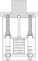
FIG. 1 is a schematic structural view of a portable water quality testing cup according to the present invention;
FIG. 2 is a schematic view of an exploded structure of a portable water quality testing cup according to the present invention;
FIG. 3 is a schematic structural view of a portable water quality detecting cup according to the present invention in a state of extracting a sample;
FIG. 4 is a schematic structural diagram of a portable water quality detecting cup according to the present invention in a state of completing a sample extraction;
in the figure, 1, a cup body; 2. an upper cover; 3. a through hole; 4. a lower cover; 5. a first clapboard; 6. a second clapboard; 7. pressing a plate; 8. a push block; 9. embedding the first groove; 10. a second embedding groove; 11. connecting holes; 12. a first through hole; 13. a second through hole; 14. a rubber layer; 15. a connecting rod; 16. a first sphere; 17. a baffle plate; 18. a spring; 19. an empty cartridge; 20. blocking edges; 21. a piston shaft; 22 a piston; 23 sphere two.
Detailed Description
The invention is described in detail below with reference to the drawings, as shown in FIGS. 1-4;
the cup is characterized in that a first partition plate 5 and a second partition plate 6 are fixedly installed in the cup body, the first partition plate is located above the second partition plate, a pressing plate 7 is further arranged in the cup body and located above the first partition plate, a pushing block 8 is arranged on the upper surface of the pressing plate, the pushing block vertically penetrates through a through hole upwards to extend out of an upper cover, an embedding groove I9 is formed in the center of the lower surface of the pressing plate, and a plurality of embedding grooves II 10 are further formed in the lower surface of the pressing plate;
the novel structure is characterized in that a connecting hole 11 is formed in the center of the first partition plate and is communicated with the upper surface and the lower surface of the first partition plate, a plurality of through holes 12 are formed in the first partition plate and are communicated with the upper surface and the lower surface of the first partition plate, the positions of the first through holes correspond to the positions of the second embedding grooves one by one, a plurality of second through holes 13 are formed in the second partition plate and correspond to the positions of the first through holes one by one, and rubber layers 14 are arranged on the inner surfaces of the first through holes and the second through holes;
the novel point of the application still lies in, is equipped with connecting rod 15 in the cup, the upper end fixed connection spheroid of connecting rod 16, the vertical embedding of spheroid upwards inlays in the groove one, the lower extreme of connecting rod is vertical to pass the connecting hole downwards and to stretch into baffle below, the lower extreme fixed connection baffle 17 of connecting rod, the connecting rod is perpendicular with the baffle, the baffle size is greater than the size of through hole one, be equipped with spring 18 between the lower surface of baffle and the upper surface of baffle two, the upper end of spring is connected with the lower surface of baffle, the lower extreme of spring and the upper surface connection of baffle two;
the utility model provides a creation point still lies in, still includes a plurality of empty section of thick bamboos 19, an empty section of thick bamboo and a through hole one-to-one, the vertical downward through hole one and through hole two of running through of an empty section of thick bamboo, the rubber layer on an empty section of thick bamboo and the two internal surfaces of through hole forms interference fit, the lower extreme port of an empty section of thick bamboo is the toper, be equipped with flange 20 on the border of empty section of thick bamboo upper end port, the flange is pressed on the upper surface of baffle one, empty section of thick bamboo interpolation dress piston shaft 21, in the empty section of thick bamboo of piston shaft lower extreme insertion, piston shaft lower extreme fixed connection piston 22, the upper end fixed connection spheroid two 23 of piston shaft, the two insets of spheroid inlay in the groove two.
The first ball body and the second ball body are both rubber balls, the first ball body is embedded into the first embedding groove to form interference fit, and the second ball body is embedded into the second embedding groove to form interference fit; the hollow cylinder is a cylinder, and the flange is a circular ring surrounding the upper end port of the hollow cylinder for one circle; the first embedding groove and the second embedding groove are both spherical grooves, and the second embedding grooves are distributed on the same circumference in an equiangular manner by taking the first embedding groove as a circle center; the edges of the first partition plate and the second partition plate are fixedly connected with the inner wall of the cup body; the edge of the pressure plate is not contacted with the inner wall of the cup body; the first through hole and the second through hole are both round holes, and the diameters of the first through hole and the second through hole are the same; the through hole is a circular hole, and the push block is cylindrical; the hollow cylinder can be vertically and upwards pulled out from the first through hole and the second through hole; the pressure plate is a circular plate, and the edge of the pressure plate is not contacted with the inner surface of the cup body.
In the implementation process of the technical scheme, the initial state is as shown in fig. 1, at the moment, the upper surface of the baffle is tightly attached to the lower surface of the first partition plate under the pushing of the spring, the first sphere is embedded in the first embedding groove, the second sphere is embedded in the corresponding second embedding groove, the lower cover is buckled on the lower end port of the cup body, and the upper cover is buckled on the upper end port of the cup body; when a sample needs to be taken, the lower cover is unscrewed, then the lower end port of the cup body extends into water to be detected, then the push block is pressed downwards, the push block pushes the press plate downwards, the press plate moves downwards and drives the connecting rod and the piston shaft to move downwards synchronously, at the moment, the connecting rod pushes the baffle plate to extrude the spring downwards, meanwhile, the piston shaft pushes the piston to extend into the empty cylinder, and air in the empty cylinder is discharged, as shown in fig. 3; then the pushing block is loosened, the spring pushes the baffle to move upwards until the upper surface of the baffle is attached to the lower surface of the first partition plate, the piston shaft drives the piston to move upwards at the moment, a detected water sample is pumped into the empty cylinder, as shown in figure 4, the cup body is taken out of water, the lower cover is screwed on, and sampling work is completed.
It is noted that, herein, relational terms such as first and second, and the like may be used solely to distinguish one entity or action from another entity or action without necessarily requiring or implying any actual such relationship or order between such entities or actions. Also, the terms "comprises," "comprising," or any other variation thereof, are intended to cover a non-exclusive inclusion, such that a process, method, article, or apparatus that comprises a list of elements does not include only those elements but may include other elements not expressly listed or inherent to such process, method, article, or apparatus. Without further limitation. The use of the phrase "comprising one of the elements does not exclude the presence of other like elements in the process, method, article, or apparatus that comprises the element.
The technical solutions described above only represent the preferred technical solutions of the present invention, and some possible modifications to some parts of the technical solutions by those skilled in the art all represent the principles of the present invention, and fall within the protection scope of the present invention.
Claims (10)
1. A portable water quality detection cup comprises a cup body (1), the cup body is cylindrical, the upper end and the lower end of the cup body are both provided with openings, the upper end of the cup body is buckled with an upper cover (2), the central position of the upper cover is provided with a through hole (3), the through hole is communicated with the upper surface and the lower surface of the upper cover, the lower end of the cup body is buckled with a lower cover (4),
a first partition plate (5) and a second partition plate (6) are fixedly installed in the cup body, the first partition plate is located above the second partition plate, a pressing plate (7) is further arranged in the cup body and located above the first partition plate, a pushing block (8) is arranged on the upper surface of the pressing plate, the pushing block vertically penetrates through the through hole upwards and extends out of the upper cover, an embedding groove I (9) is formed in the center of the lower surface of the pressing plate, and a plurality of embedding grooves II (10) are further formed in the lower surface of the pressing plate;
a connecting hole (11) is formed in the center of the first partition plate and is communicated with the upper surface and the lower surface of the first partition plate, a plurality of through holes (12) are further formed in the first partition plate and are communicated with the upper surface and the lower surface of the first partition plate, the positions of the through holes (I) are in one-to-one correspondence with the positions of the embedding grooves (II), a plurality of through holes (13) are formed in the second partition plate, the positions of the through holes (II) are in one-to-one correspondence with the positions of the through holes (I), and rubber layers (14) are arranged on the inner surfaces of the through holes (I) and the through holes (II);
a connecting rod (15) is arranged in the cup body, the upper end of the connecting rod is fixedly connected with a first sphere (16), the first sphere is vertically upwards embedded into the first embedding groove, the lower end of the connecting rod vertically downwards penetrates through the connecting hole and extends into the lower portion of the partition plate, the lower end of the connecting rod is fixedly connected with a baffle (17), the connecting rod is perpendicular to the baffle, the size of the baffle is larger than that of the first penetrating hole, a spring (18) is arranged between the lower surface of the baffle and the upper surface of the second partition plate, the upper end of the spring is connected with the lower surface of the baffle, and the lower end of the spring is connected with the upper surface of the second partition plate;
still include a plurality of empty section of thick bamboos (19), empty section of thick bamboos and through hole one-to-one, the vertical through hole that runs through downwards of empty section of thick bamboo one and through hole two, the rubber layer on empty section of thick bamboo and the two internal surfaces of through hole forms interference fit, the lower extreme port of empty section of thick bamboo is the toper, be equipped with flange (20) on the border of empty section of thick bamboo upper end port, the flange is pressed on the upper surface of baffle one, empty section of thick bamboo interpolation dress piston shaft (21), the piston shaft lower extreme inserts in the empty section of thick bamboo, piston shaft lower extreme fixed connection piston (22), the upper end fixed connection spheroid two (23) of piston shaft, the inslot is inlayed in the two imbeds to spheroid.
2. The portable water quality detection cup according to claim 1, wherein the first ball body and the second ball body are both rubber balls, the first ball body is embedded in the first embedded groove to form an interference fit, and the second ball body is embedded in the second embedded groove to form an interference fit.
3. The portable water quality detection cup according to claim 1, wherein the hollow cylinder is a cylinder, and the rib is a circular ring surrounding a circumference of an upper end port of the hollow cylinder.
4. The portable water quality detection cup according to claim 1, wherein the first embedding groove and the second embedding groove are both spherical grooves, and the first embedding groove and the second embedding groove are distributed on the same circumference at equal angles by taking the first embedding groove as a circle center.
5. The portable water quality detection cup according to claim 1, wherein the edges of the first partition plate and the second partition plate are fixedly connected with the inner wall of the cup body.
6. The portable water quality detecting cup according to claim 1, wherein the edge of the pressure plate does not contact the inner wall of the cup body.
7. The portable water quality detection cup according to claim 1, wherein the first through hole and the second through hole are both circular holes, and the diameters of the first through hole and the second through hole are the same.
8. The portable water quality detecting cup according to claim 1, wherein the through hole is a circular hole, and the push block is cylindrical.
9. The portable water quality detecting cup according to claim 1, wherein the hollow cylinder can be vertically and upwardly pulled out from the first through hole and the second through hole.
10. The portable water quality detecting cup according to claim 1, wherein the pressure plate is a circular plate, and the edge of the pressure plate does not contact with the inner surface of the cup body.
Priority Applications (1)
| Application Number | Priority Date | Filing Date | Title |
|---|---|---|---|
| CN202110257510.7A CN113049765B (en) | 2021-03-09 | 2021-03-09 | Portable water quality testing cup |
Applications Claiming Priority (1)
| Application Number | Priority Date | Filing Date | Title |
|---|---|---|---|
| CN202110257510.7A CN113049765B (en) | 2021-03-09 | 2021-03-09 | Portable water quality testing cup |
Publications (2)
| Publication Number | Publication Date |
|---|---|
| CN113049765A CN113049765A (en) | 2021-06-29 |
| CN113049765B true CN113049765B (en) | 2022-12-09 |
Family
ID=76510786
Family Applications (1)
| Application Number | Title | Priority Date | Filing Date |
|---|---|---|---|
| CN202110257510.7A Active CN113049765B (en) | 2021-03-09 | 2021-03-09 | Portable water quality testing cup |
Country Status (1)
| Country | Link |
|---|---|
| CN (1) | CN113049765B (en) |
Families Citing this family (2)
| Publication number | Priority date | Publication date | Assignee | Title |
|---|---|---|---|---|
| CN115932206A (en) * | 2023-02-28 | 2023-04-07 | 四川君逸数码科技股份有限公司 | Tracing monitoring device and method for overproof sewage |
| CN116183856B (en) * | 2023-03-14 | 2024-02-09 | 山东遂真信息技术有限公司 | River water quality monitoring device |
Citations (10)
| Publication number | Priority date | Publication date | Assignee | Title |
|---|---|---|---|---|
| JPH09243632A (en) * | 1996-03-13 | 1997-09-19 | Suido Kiko Kaisha Ltd | Portable water quality inspection apparatus |
| JP2009222440A (en) * | 2008-03-13 | 2009-10-01 | Nippon Suiki Chosa Kk | Water examination device |
| WO2013004927A1 (en) * | 2011-07-05 | 2013-01-10 | Valorhiz | Device for measurement coupled with water parameters of soil |
| CN206876692U (en) * | 2017-05-11 | 2018-01-12 | 刘剑锐 | A kind of online water quality monitor |
| CN108896727A (en) * | 2018-06-15 | 2018-11-27 | 山东五洲检测有限公司 | A kind of Stratified Sampling formula water quality detecting device |
| CN209841449U (en) * | 2018-12-29 | 2019-12-24 | 南京大劲精密机械有限公司 | COD detecting instrument |
| CN210037785U (en) * | 2019-05-28 | 2020-02-07 | 四川大序环境建设有限公司 | Simple water quality real-time early warning device |
| CN110927355A (en) * | 2019-12-27 | 2020-03-27 | 张瑞萍 | Water quality detection cup |
| CN210269811U (en) * | 2019-06-11 | 2020-04-07 | 蒙城县中益机械科技有限公司 | Water quality detection device of non-negative pressure water supply equipment |
| CN210376315U (en) * | 2019-04-23 | 2020-04-21 | 青岛引黄济青水务有限责任公司 | Water quality detection and analysis device |
-
2021
- 2021-03-09 CN CN202110257510.7A patent/CN113049765B/en active Active
Patent Citations (10)
| Publication number | Priority date | Publication date | Assignee | Title |
|---|---|---|---|---|
| JPH09243632A (en) * | 1996-03-13 | 1997-09-19 | Suido Kiko Kaisha Ltd | Portable water quality inspection apparatus |
| JP2009222440A (en) * | 2008-03-13 | 2009-10-01 | Nippon Suiki Chosa Kk | Water examination device |
| WO2013004927A1 (en) * | 2011-07-05 | 2013-01-10 | Valorhiz | Device for measurement coupled with water parameters of soil |
| CN206876692U (en) * | 2017-05-11 | 2018-01-12 | 刘剑锐 | A kind of online water quality monitor |
| CN108896727A (en) * | 2018-06-15 | 2018-11-27 | 山东五洲检测有限公司 | A kind of Stratified Sampling formula water quality detecting device |
| CN209841449U (en) * | 2018-12-29 | 2019-12-24 | 南京大劲精密机械有限公司 | COD detecting instrument |
| CN210376315U (en) * | 2019-04-23 | 2020-04-21 | 青岛引黄济青水务有限责任公司 | Water quality detection and analysis device |
| CN210037785U (en) * | 2019-05-28 | 2020-02-07 | 四川大序环境建设有限公司 | Simple water quality real-time early warning device |
| CN210269811U (en) * | 2019-06-11 | 2020-04-07 | 蒙城县中益机械科技有限公司 | Water quality detection device of non-negative pressure water supply equipment |
| CN110927355A (en) * | 2019-12-27 | 2020-03-27 | 张瑞萍 | Water quality detection cup |
Also Published As
| Publication number | Publication date |
|---|---|
| CN113049765A (en) | 2021-06-29 |
Similar Documents
| Publication | Publication Date | Title |
|---|---|---|
| CN113049765B (en) | Portable water quality testing cup | |
| CN101103906B (en) | Pulse condition collecting device and using method thereof | |
| CN209342677U (en) | The air detection instrument that the air in different height space is detected | |
| CN2842409Y (en) | Novel pavement infiltration instrument | |
| CN212059424U (en) | Soil sampling device is used to agricultural | |
| CN108678035B (en) | Annular sounding device for detecting side friction force in sinking process of cylindrical foundation | |
| CN214716750U (en) | Application of sample rifle of nuclear medicine branch of academic or vocational study | |
| CN204855213U (en) | Depthkeeping piston water sampling ware | |
| CN110926880B (en) | Deep quality of water sampling device based on environmental protection | |
| CN102519754A (en) | Deep water sample collector | |
| CN211205835U (en) | Sampler for pesticide residue test | |
| CN113588343B (en) | Sewage cross section sampling device for water quality environment detection | |
| CN210810985U (en) | Skin elasticity detection device | |
| CN212008236U (en) | Waterproof testing arrangement of cable | |
| CN208013067U (en) | A kind of saliva detection device | |
| CN211954796U (en) | Water sample collection system | |
| CN210090278U (en) | Seal paint film drying tester | |
| CN200941101Y (en) | Fast analysis for vaginitis PH/amine | |
| CN209820831U (en) | Water quality layered sampler | |
| CN207976402U (en) | A kind of saliva Test paper device | |
| CN109507381B (en) | A kind of mudflat seawater water monitoring device | |
| CN216593891U (en) | Water and soil pressure dual-purpose testing device | |
| CN219224208U (en) | Soil quantitative sampler | |
| CN208013065U (en) | A kind of double-layer structure saliva detection bottle | |
| CN220218702U (en) | Punching machine for intelligent water meter shell |
Legal Events
| Date | Code | Title | Description |
|---|---|---|---|
| PB01 | Publication | ||
| PB01 | Publication | ||
| SE01 | Entry into force of request for substantive examination | ||
| SE01 | Entry into force of request for substantive examination | ||
| GR01 | Patent grant | ||
| GR01 | Patent grant |