CN113030383A - Atmospheric environmental pollution monitoring device capable of being adaptively adjusted according to wind direction - Google Patents
Atmospheric environmental pollution monitoring device capable of being adaptively adjusted according to wind direction Download PDFInfo
- Publication number
- CN113030383A CN113030383A CN202110213906.1A CN202110213906A CN113030383A CN 113030383 A CN113030383 A CN 113030383A CN 202110213906 A CN202110213906 A CN 202110213906A CN 113030383 A CN113030383 A CN 113030383A
- Authority
- CN
- China
- Prior art keywords
- block
- environmental pollution
- monitoring device
- pollution monitoring
- atmospheric environmental
- Prior art date
- Legal status (The legal status is an assumption and is not a legal conclusion. Google has not performed a legal analysis and makes no representation as to the accuracy of the status listed.)
- Granted
Links
Images


Classifications
-
- G—PHYSICS
- G01—MEASURING; TESTING
- G01N—INVESTIGATING OR ANALYSING MATERIALS BY DETERMINING THEIR CHEMICAL OR PHYSICAL PROPERTIES
- G01N33/00—Investigating or analysing materials by specific methods not covered by groups G01N1/00 - G01N31/00
- G01N33/0004—Gaseous mixtures, e.g. polluted air
- G01N33/0009—General constructional details of gas analysers, e.g. portable test equipment
-
- Y—GENERAL TAGGING OF NEW TECHNOLOGICAL DEVELOPMENTS; GENERAL TAGGING OF CROSS-SECTIONAL TECHNOLOGIES SPANNING OVER SEVERAL SECTIONS OF THE IPC; TECHNICAL SUBJECTS COVERED BY FORMER USPC CROSS-REFERENCE ART COLLECTIONS [XRACs] AND DIGESTS
- Y02—TECHNOLOGIES OR APPLICATIONS FOR MITIGATION OR ADAPTATION AGAINST CLIMATE CHANGE
- Y02A—TECHNOLOGIES FOR ADAPTATION TO CLIMATE CHANGE
- Y02A50/00—TECHNOLOGIES FOR ADAPTATION TO CLIMATE CHANGE in human health protection, e.g. against extreme weather
- Y02A50/20—Air quality improvement or preservation, e.g. vehicle emission control or emission reduction by using catalytic converters
Landscapes
- Chemical & Material Sciences (AREA)
- Life Sciences & Earth Sciences (AREA)
- Engineering & Computer Science (AREA)
- Health & Medical Sciences (AREA)
- Medicinal Chemistry (AREA)
- Food Science & Technology (AREA)
- Combustion & Propulsion (AREA)
- Physics & Mathematics (AREA)
- Analytical Chemistry (AREA)
- Biochemistry (AREA)
- General Health & Medical Sciences (AREA)
- General Physics & Mathematics (AREA)
- Immunology (AREA)
- Pathology (AREA)
- Indicating Or Recording The Presence, Absence, Or Direction Of Movement (AREA)
Abstract
The invention discloses an atmospheric environmental pollution monitoring device capable of being adjusted in a self-adaptive mode according to wind directions, which comprises a base, a supporting block, a support and a gas detector, wherein the supporting block is arranged above the base, the support is arranged above the supporting block, the gas detector is fixed above the support, a transmission pipe is connected to the upper bearing of the gas detector, an air inlet pipe is connected above the transmission pipe, and a driving plate is fixed at the upper end of the air inlet pipe. This atmospheric environmental pollution monitoring devices that can carry out self-adaptation adjustment according to wind direction is provided with drive plate and one-way conduction structure, can blow the drive plate and remove when the wind direction changes to drive the air-supply line and remove, make it keep and wind direction parallel, cooperation one-way conduction structure makes the gas when parallel no matter enter into the transmission pipe smoothly from the left side of guide duct or right side homoenergetic, guarantee that the follow-up ability of device is effectual monitors gas environment, increase the functionality of device.
Description
Technical Field
The invention relates to the technical field of air environment monitoring, in particular to an atmospheric environmental pollution monitoring device capable of being adaptively adjusted according to the wind direction.
Background
Along with the improvement of environmental protection consciousness, people also attach more and more importance to atmospheric environment, will influence people's healthy when atmospheric environment receives the pollution, when managing atmospheric environment, accessible atmospheric pollution monitoring devices monitors surrounding gas environment, but current monitoring devices still has some weak points when using:
1. when the existing detection device is used, the external gas environment is generally monitored only through one oriented gas collection pipeline, the direction of the collection pipeline cannot be adjusted when the wind direction is changed, the accuracy of monitoring the gas environment is greatly reduced under the leeward condition, the gas cannot be effectively collected, and the functionality of the device is reduced;
2. the existing detection device is generally directly installed on a fixed supporting rod for use, the fixed supporting rod is inconvenient to carry and transport due to the length of the fixed supporting rod, equipment such as a climbing frame is needed when the device is required to be overhauled subsequently, and meanwhile, certain overhaul risks can be increased due to high-altitude operation.
In order to solve the above problems, innovative design based on the original detection device is urgently needed.
Disclosure of Invention
The invention aims to provide an atmospheric environmental pollution monitoring device capable of self-adaptively adjusting according to wind direction, the prior detection device in the market proposed by the background art generally monitors the external gas environment only through one oriented gas collection pipeline when in use, and the direction of the collection pipe can not be adjusted when the wind direction changes, the accuracy of monitoring the gas environment under the leeward condition is greatly reduced, and the gas can not be effectively collected, and current detection device generally is that direct mount uses on fixed support bar, and fixed bracing piece all has inconveniently when carrying and transporting because the reason of self length leads to it, and follow-up needs need be overhauld the device spare with the help of equipment such as climbing frame, and aerial work also can increase the problem of certain maintenance risk simultaneously.
In order to achieve the purpose, the invention provides the following technical scheme: an atmospheric environmental pollution monitoring device capable of being adjusted in a self-adaptive mode according to wind directions comprises a base, supporting blocks, a support and a gas detector, wherein the supporting blocks are arranged above the base, the support is arranged above the supporting blocks, the gas detector is fixed above the support, a transmission pipe is connected to a bearing above the gas detector, an air inlet pipe is connected to the upper side of the transmission pipe, a driving plate is fixed to the upper end of the air inlet pipe, the inside of the transmission pipe and the inside of the air inlet pipe are communicated, a one-way conduction structure is arranged inside the air inlet pipe, a connecting block is arranged inside the supporting blocks, a second return spring is nested on the surface of the connecting block, a connecting rope is arranged inside the connecting block, a limiting block is connected to the upper end of the connecting rope, a third return spring is nested on the surface of the limiting block, and a first magnet is nested at the left, the outside of stopper is provided with the spread groove, and the inner wall of spread groove is fixed with the second magnet, the upper end of connecting block is fixed with the third magnet, and the top of third magnet is provided with the fourth magnet, the lower extreme of connecting the rope is connected with the loose axle, the draw-in groove has been seted up on the surface of supporting shoe, and the inside of draw-in groove is provided with the fixture block to the outside of fixture block is provided with the movable block, and the inside of movable block is provided with fifth reset spring, the internal connection of movable block has the actuating lever.
Preferably, both ends all are the design of slope column structure about the air-supply line, and the tip of air-supply line is provided with the filter screen to air-supply line and drive plate parallel arrangement, the air-supply line constitutes revolution mechanic through between transmission pipe and the gas detector simultaneously.
Preferably, the support column is fixed with below of air-supply line, and the ball is installed to the below of support column to the outside of support column is connected with the fixed block, and the guide way has been seted up to the inside of fixed block simultaneously, constitute sliding connection between support column and the guide way.
Preferably, the one-way conduction structure comprises a baffle, a through opening, a sealing block, a first return spring, a guide rod and a mounting plate, and the one-way conduction structure is arranged in bilateral symmetry with respect to the center line of the transmission pipe.
Preferably, the opening has been seted up on the surface of baffle, and the inside of opening is provided with sealed piece to the inner of baffle is connected with first reset spring, and first reset spring's inside nestification has the guide bar simultaneously, the right-hand member of guide bar runs through there is the mounting panel, and constitutes left and right sliding connection between guide bar and the mounting panel.
Preferably, the bottom of connecting block and supporting shoe constitutes unsmooth cooperation structure, and the connecting block passes through and constitutes sliding structure from top to bottom between second reset spring and the supporting shoe to constitute sliding structure from top to bottom between supporting shoe and the base, the right side of base is the structural design of opening form simultaneously.
Preferably, the first magnet and the second magnet and the third magnet and the fourth magnet are arranged in opposite directions with different magnetic poles, an integrated structure is formed between the first magnet and the limiting block, and the limiting block is connected with the movable shaft through a connecting rope.
Preferably, the left end of loose axle is provided with the connection pad, and the left side of connection pad is provided with the transmission piece to constitute unsmooth cooperation structure between transmission piece and the connection pad, the left end of transmission piece is connected with the movable rod simultaneously, the clamp plate is installed to the surface bearing of movable rod, and the right side of clamp plate is connected with fourth reset spring.
Preferably, constitute threaded connection between actuating lever and the movable block, and the lower extreme of actuating lever is connected with the connecting band to the inner of connecting band is connected with the motor.
Compared with the prior art, the invention has the beneficial effects that: the atmospheric environmental pollution monitoring device can be adaptively adjusted according to the wind direction;
(1) the air inlet pipe is provided with a driving plate and a one-way conduction structure, when the wind direction changes, the driving plate can be blown to move, so that the air inlet pipe is driven to move, the air direction is kept parallel to the wind direction, and the one-way conduction structure is matched to enable air in parallel to smoothly enter the transmission pipe from the left side or the right side of the air guide pipe, so that the follow-up performance of the device can be effectively monitored for the air environment, and the functionality of the device is improved;
(2) the connecting block and the limiting block are arranged, the positions of the limiting block and the connecting block can be controlled through mutual attraction between the first magnet and the second magnet and between the third magnet and the fourth magnet, adjacent supporting blocks are connected through the limiting block and the connecting block, subsequent splicing is facilitated, and meanwhile the device is convenient to transport and carry;
(3) be provided with movable block and actuating lever, the accessible actuating lever drives the movable block and removes, makes the movable block control the position of supporting shoe through the cooperation of fixture block and draw-in groove, conveniently carries out subsequent concatenation and dismantlement to the supporting shoe of below, improves the use convenience of device.
Drawings
FIG. 1 is a schematic front view of the present invention;
FIG. 2 is a schematic view of the main section of the air inlet pipe according to the present invention;
FIG. 3 is a schematic top view of the drive plate of the present invention;
FIG. 4 is an enlarged view of the structure at A in FIG. 2 according to the present invention;
FIG. 5 is a schematic view of a main sectional structure of the base of the present invention;
FIG. 6 is an enlarged view of the structure at B in FIG. 5 according to the present invention;
FIG. 7 is a schematic side sectional view of the base of the present invention;
FIG. 8 is a schematic view of a top-down structure of the movable block of the present invention.
In the figure: 1. a base; 2. a support block; 3. a support; 4. a gas detector; 5. a conveying pipe; 6. an air inlet pipe; 7. a drive plate; 8. a filter screen; 9. a support pillar; 10. a ball bearing; 11. a fixed block; 12. a guide groove; 13. a baffle plate; 14. a port; 15. a sealing block; 16. a first return spring; 17. a guide bar; 18. mounting a plate; 19. connecting blocks; 20. a second return spring; 21. connecting ropes; 22. a limiting block; 23. a third return spring; 24. a first magnet; 25. connecting grooves; 26. a second magnet; 27. a third magnet; 28. a fourth magnet; 29. a movable shaft; 30. a connecting disc; 31. a transmission block; 32. a movable rod; 33. a fourth return spring; 34. pressing a plate; 35. a card slot; 36. a clamping block; 37. a fifth return spring; 38. a movable block; 39. a drive rod; 40. a connecting belt; 41. an electric motor.
Detailed Description
The technical solutions in the embodiments of the present invention will be clearly and completely described below with reference to the drawings in the embodiments of the present invention, and it is obvious that the described embodiments are only a part of the embodiments of the present invention, and not all of the embodiments. All other embodiments, which can be derived by a person skilled in the art from the embodiments given herein without making any creative effort, shall fall within the protection scope of the present invention.
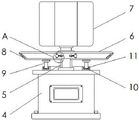
Referring to fig. 1-8, the present invention provides a technical solution: an atmospheric environmental pollution monitoring device capable of being adjusted in a self-adaptive mode according to wind directions comprises a base 1, supporting blocks 2, a support 3 and a gas detector 4, wherein the supporting blocks 2 are arranged above the base 1, the support 3 is arranged above the supporting blocks 2, the gas detector 4 is fixed above the support 3, a transmission pipe 5 is connected to the upper portion of the gas detector 4 through a bearing, an air inlet pipe 6 is connected to the upper portion of the transmission pipe 5, a driving plate 7 is fixed to the upper end of the air inlet pipe 6, the interior of the transmission pipe 5 is communicated with the interior of the air inlet pipe 6, a one-way conduction structure is arranged inside the air inlet pipe 6, a connecting block 19 is arranged inside the supporting blocks 2, a second reset spring 20 is embedded on the surface of the connecting block 19, a connecting rope 21 is arranged inside the connecting block 19, a limiting block 22 is connected to the upper end of the connecting rope 21, and a third reset spring 23 is, a first magnet 24 is inlaid at the left end of the limiting block 22, a connecting groove 25 is formed in the outer side of the limiting block 22, a second magnet 26 is fixed on the inner wall of the connecting groove 25, a third magnet 27 is fixed at the upper end of the connecting block 19, a fourth magnet 28 is arranged above the third magnet 27, the lower end of the connecting rope 21 is connected with a movable shaft 29, a clamping groove 35 is formed in the surface of the supporting block 2, a clamping block 36 is arranged inside the clamping groove 35, a movable block 38 is arranged on the outer side of the clamping block 36, a fifth return spring 37 is arranged inside the movable block 38, and a driving rod 39 is connected inside the movable block 38;
the left end and the right end of the air inlet pipe 6 are both designed in an inclined structure, the end part of the air inlet pipe 6 is provided with the filter screen 8, the air inlet pipe 6 and the drive plate 7 are arranged in parallel, meanwhile, the air inlet pipe 6 forms a rotating structure through the transmission pipe 5 and the gas detector 4, the structural design facilitates the subsequent adjustment of the position of the air inlet pipe 6 through the movement of the drive plate 7, and the gas can be effectively collected;
a support column 9 is fixed below the air inlet pipe 6, a ball 10 is arranged below the support column 9, a fixed block 11 is connected to the outer side of the support column 9, a guide groove 12 is formed in the fixed block 11, and the support column 9 and the guide groove 12 are in sliding connection;
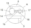
the one-way conduction structure comprises a baffle 13, a through hole 14, a sealing block 15, a first return spring 16, a guide rod 17 and a mounting plate 18, the one-way conduction structure is arranged in bilateral symmetry about the center line of the transmission pipe 5, the through hole 14 is formed in the surface of the baffle 13, the sealing block 15 is arranged inside the through hole 14, the first return spring 16 is connected to the inner end of the baffle 13, the guide rod 17 is nested inside the first return spring 16, the mounting plate 18 penetrates through the right end of the guide rod 17, and left-right sliding connection is formed between the guide rod 17 and the mounting plate 18;
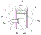
the connecting block 19 and the bottom of the supporting block 2 form a concave-convex matching structure, the connecting block 19 forms a vertical sliding structure through the space between the second return spring 20 and the supporting block 2, the supporting block 2 and the base 1 form a vertical sliding structure, meanwhile, the right side of the base 1 is designed to be in an opening-shaped structure, the first magnet 24 and the second magnet 26, the third magnet 27 and the fourth magnet 28 are oppositely arranged in a different magnetic pole way, the first magnet 24 and the limiting block 22 form an integrated structure, the limiting block 22 is connected with the movable shaft 29 through the connecting rope 21, the left end of the movable shaft 29 is provided with the connecting disc 30, the left side of the connecting disc 30 is provided with the driving block 31, the driving block 31 and the connecting disc 30 form a concave-convex matching structure, meanwhile, the left end of the driving block 31 is connected with the movable rod 32, and the surface bearing of the movable rod 32 is, the right side of the pressure plate 34 is connected with a fourth return spring 33, the position of the limiting block 22 can be controlled by the rotation of the subsequent movable shaft 29 and the connection disc 30, and the supporting block 2 can be pushed out by the movement of the movable rod 32;
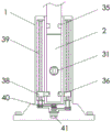
the driving rod 39 and the movable block 38 form a threaded connection, the lower end of the driving rod 39 is connected with a connecting belt 40, the inner end of the connecting belt 40 is connected with a motor 41, and the structural design can control the position of the movable block 38 through the rotation of the subsequent driving rod 39, so that the position of the supporting block 2 is controlled by matching with the fixture block 36.
The working principle is as follows: when the atmospheric environmental pollution monitoring device capable of self-adaptively adjusting according to the wind direction is used, firstly, according to the illustration in fig. 1, when the device is used, the external air can be collected through the air inlet pipe 6, when the wind direction changes, the driving plate 7 is blown by the wind force to rotate by combining the illustrations in fig. 2 and 3, so that the air direction of the driving plate 7 is kept parallel, the driving plate 7 drives the air inlet pipe 6 to move, the air inlet pipe 6 drives the transmission pipe 5 to rotate on the gas detector 4, so that the position of the air inlet pipe 6 is automatically adjusted, the wind direction is kept parallel, and at the moment, as shown in the illustration in fig. 4, the wind direction can smoothly enter the transmission pipe 5 through the one-way conduction structure in the air inlet pipe 6 from left to right or from right to left, and then enters the gas detector 4 to be detected, so that the accuracy of subsequent detection is;
when the height of the device needs to be adjusted or the supporting blocks 2 need to be spliced, as shown in fig. 5-8, a motor 41 can drive a driving rod 39 to rotate, the driving rod 39 drives a movable block 38 to move, the movable block 38 drives the supporting blocks 2 to move upwards in the base 1 through the clamping of a clamping block 36 and a clamping groove 35, when the supporting blocks 2 move upwards to the end, a new supporting block 2 can be horizontally inserted into the base 1 to be positioned below the original supporting block 2, at the moment, a fourth magnet 28 attracts a third magnet 27 to enable a connecting block 19 to enter the supporting block 2, after the connecting block 19 enters, the first magnet 24 and the second magnet 26 attract each other to enable a limiting block 22 to enter a connecting groove 25, so that the supporting blocks 2 are spliced, when the supporting blocks need to be taken down, the movable rod 32 can be pressed to enable a transmission block 31 to be clamped into a connecting disc 30, and the movable rod 32 is rotated to drive a movable shaft 29 to rotate, the movable shaft 29 sequentially pulls the limiting block 22 and the connecting block 19 through the connecting rope 21 to move, the connection between the limiting block and the supporting block 2 is released, then the movable rod 32 is continuously pushed to push the supporting block 2 out, and after the movable rod is pushed out, the movable block 38 is controlled to move downwards to move the original supporting block 2 downwards, so that the use convenience of the device is improved, and the carrying and the transportation of the device are facilitated.
Those not described in detail in this specification are within the skill of the art.
Although the present invention has been described in detail with reference to the foregoing embodiments, it will be apparent to those skilled in the art that various changes in the embodiments and/or modifications of the invention can be made, and equivalents and modifications of some features of the invention can be made without departing from the spirit and scope of the invention.
Claims (9)
1. The utility model provides a can carry out self-adaptation adjustment's atmospheric environmental pollution monitoring devices according to wind direction, includes base (1), supporting shoe (2), support (3) and gas detector (4), its characterized in that: the gas detection device is characterized in that a supporting block (2) is arranged above the base (1), a support (3) is arranged above the supporting block (2), a gas detector (4) is fixed above the support (3), a transmission pipe (5) is connected to a bearing above the gas detector (4), an air inlet pipe (6) is connected above the transmission pipe (5), a driving plate (7) is fixed at the upper end of the air inlet pipe (6), the inside of the transmission pipe (5) is communicated with the inside of the air inlet pipe (6), a one-way conduction structure is arranged inside the air inlet pipe (6), a connecting block (19) is arranged inside the supporting block (2), a second reset spring (20) is nested on the surface of the connecting block (19), a connecting rope (21) is arranged inside the connecting block (19), and a limiting block (22) is connected to the upper end of the connecting rope (21), and the surface of stopper (22) nests there is third reset spring (23) to the left end of stopper (22) is inlayed and is had first magnet (24), the outside of stopper (22) is provided with spread groove (25), and the inner wall of spread groove (25) is fixed with second magnet (26), the upper end of connecting block (19) is fixed with third magnet (27), and the top of third magnet (27) is provided with fourth magnet (28), the lower extreme of connecting rope (21) is connected with loose axle (29), draw-in groove (35) have been seted up on the surface of supporting shoe (2), and the inside of draw-in groove (35) is provided with fixture block (36), and the outside of fixture block (36) is provided with movable block (38), and the inside of movable block (38) is provided with fifth reset spring (37), the internal connection of movable block (38) has actuating lever (39).
2. The atmospheric environmental pollution monitoring device according to claim 1, wherein the atmospheric environmental pollution monitoring device is capable of performing adaptive adjustment according to a wind direction, and comprises: both ends all are the design of slope column structure about air-supply line (6), and the tip of air-supply line (6) is provided with filter screen (8) to air-supply line (6) and drive plate (7) parallel arrangement, constitute revolution mechanic simultaneously between air-supply line (6) through transmission pipe (5) and gas detector (4).
3. The atmospheric environmental pollution monitoring device according to claim 2, wherein the atmospheric environmental pollution monitoring device is capable of performing adaptive adjustment according to a wind direction, and comprises: the air inlet pipe is characterized in that a support column (9) is fixed below the air inlet pipe (6), a ball (10) is installed below the support column (9), a fixed block (11) is connected to the outer side of the support column (9), a guide groove (12) is formed in the fixed block (11), and the support column (9) is connected with the guide groove (12) in a sliding mode.
4. The atmospheric environmental pollution monitoring device according to claim 1, wherein the atmospheric environmental pollution monitoring device is capable of performing adaptive adjustment according to a wind direction, and comprises: the one-way conduction structure comprises a baffle (13), a through opening (14), a sealing block (15), a first return spring (16), a guide rod (17) and a mounting plate (18), and the one-way conduction structure is arranged in bilateral symmetry with respect to the center line of the transmission pipe (5).
5. The atmospheric environmental pollution monitoring device according to claim 4, wherein the atmospheric environmental pollution monitoring device is capable of performing adaptive adjustment according to a wind direction, and comprises: opening (14) have been seted up on the surface of baffle (13), and the inside of opening (14) is provided with sealed piece (15) to the inner of baffle (13) is connected with first reset spring (16), and the inside nestification of first reset spring (16) has guide bar (17) simultaneously, the right-hand member of guide bar (17) has run through mounting panel (18), and constitutes left and right sliding connection between guide bar (17) and mounting panel (18).
6. The atmospheric environmental pollution monitoring device according to claim 1, wherein the atmospheric environmental pollution monitoring device is capable of performing adaptive adjustment according to a wind direction, and comprises: the bottom of connecting block (19) and supporting shoe (2) constitutes unsmooth cooperation structure, and sliding structure about connecting block (19) passes through between second reset spring (20) and supporting shoe (2) and constitutes between supporting shoe (2) and base (1) to sliding structure about constituting between supporting shoe (2) and base (1), the right side of base (1) is the structural design of opening form simultaneously.
7. The atmospheric environmental pollution monitoring device according to claim 6, wherein the atmospheric environmental pollution monitoring device is capable of performing adaptive adjustment according to a wind direction, and comprises: the first magnet (24) and the second magnet (26) and the third magnet (27) and the fourth magnet (28) are arranged in opposite directions with different magnetic poles, the first magnet (24) and the limiting block (22) form an integrated structure, and the limiting block (22) is connected with the movable shaft (29) through the connecting rope (21).
8. The atmospheric environmental pollution monitoring device according to claim 7, wherein the atmospheric environmental pollution monitoring device is capable of performing adaptive adjustment according to a wind direction, and comprises: the left end of loose axle (29) is provided with connection pad (30), and the left side of connection pad (30) is provided with transmission piece (31) to constitute unsmooth cooperation structure between transmission piece (31) and connection pad (30), the left end of transmission piece (31) is connected with movable rod (32) simultaneously, clamp plate (34) are installed to the surface bearing of movable rod (32), and the right side of clamp plate (34) is connected with fourth reset spring (33).
9. The atmospheric environmental pollution monitoring device according to claim 8, wherein the atmospheric environmental pollution monitoring device is adapted according to a wind direction, and comprises: constitute threaded connection between actuating lever (39) and movable block (38), and the lower extreme of actuating lever (39) is connected with connecting band (40), and the inner of connecting band (40) is connected with motor (41).
Priority Applications (1)
| Application Number | Priority Date | Filing Date | Title |
|---|---|---|---|
| CN202110213906.1A CN113030383B (en) | 2021-02-26 | 2021-02-26 | Atmospheric environmental pollution monitoring device capable of performing self-adaptive adjustment according to wind direction |
Applications Claiming Priority (1)
| Application Number | Priority Date | Filing Date | Title |
|---|---|---|---|
| CN202110213906.1A CN113030383B (en) | 2021-02-26 | 2021-02-26 | Atmospheric environmental pollution monitoring device capable of performing self-adaptive adjustment according to wind direction |
Publications (2)
| Publication Number | Publication Date |
|---|---|
| CN113030383A true CN113030383A (en) | 2021-06-25 |
| CN113030383B CN113030383B (en) | 2023-08-08 |
Family
ID=76462195
Family Applications (1)
| Application Number | Title | Priority Date | Filing Date |
|---|---|---|---|
| CN202110213906.1A Active CN113030383B (en) | 2021-02-26 | 2021-02-26 | Atmospheric environmental pollution monitoring device capable of performing self-adaptive adjustment according to wind direction |
Country Status (1)
| Country | Link |
|---|---|
| CN (1) | CN113030383B (en) |
Cited By (2)
| Publication number | Priority date | Publication date | Assignee | Title |
|---|---|---|---|---|
| CN113720974A (en) * | 2021-11-03 | 2021-11-30 | 张家港谱析传感科技有限公司 | Environmental pollution monitoring instrument |
| CN116448949A (en) * | 2023-03-22 | 2023-07-18 | 宁波远亚车辆检测有限公司 | Automobile pollutant detection method, system, intelligent terminal and storage medium |
Citations (11)
| Publication number | Priority date | Publication date | Assignee | Title |
|---|---|---|---|---|
| CN204856870U (en) * | 2015-08-04 | 2015-12-09 | 河北翰智物联网科技有限公司 | Rotation type air monitoring appearance based on zigBee wireless communication |
| CN206738650U (en) * | 2017-04-12 | 2017-12-12 | 浙江冠正阀门股份有限公司 | A kind of natural gas valve |
| CN208350091U (en) * | 2018-07-06 | 2019-01-08 | 北京农学院 | It is a kind of with the measurement line rod for founding straight frame |
| CN209399979U (en) * | 2019-02-15 | 2019-09-17 | 广州兴粤勘测设计研究有限公司 | A kind of depth of water prospecting measuring device |
| CN210266651U (en) * | 2019-07-26 | 2020-04-07 | 河南唐诚科技有限公司 | Portable electronic equipment mounting structure of convenient equipment |
| CN211013709U (en) * | 2019-11-27 | 2020-07-14 | 上海盛剑环境系统科技股份有限公司 | Pollutant sampling device for atmospheric pollution treatment |
| CN211260129U (en) * | 2019-12-25 | 2020-08-14 | 广东科迪隆科技有限公司 | Raise dust automatic monitoring device |
| CN211317892U (en) * | 2019-12-30 | 2020-08-21 | 纪轶 | Environmental monitoring flue gas sampling instrument |
| CN211784996U (en) * | 2020-04-09 | 2020-10-27 | 盖玉刚 | Novel construction engineering atmospheric environment detects device |
| CN112303509A (en) * | 2020-11-16 | 2021-02-02 | 王润枝 | Movable lighting equipment for constructional engineering |
| CN112305173A (en) * | 2020-11-24 | 2021-02-02 | 江苏恩测检测技术有限公司 | Novel construction engineering atmospheric environment detects device |
-
2021
- 2021-02-26 CN CN202110213906.1A patent/CN113030383B/en active Active
Patent Citations (11)
| Publication number | Priority date | Publication date | Assignee | Title |
|---|---|---|---|---|
| CN204856870U (en) * | 2015-08-04 | 2015-12-09 | 河北翰智物联网科技有限公司 | Rotation type air monitoring appearance based on zigBee wireless communication |
| CN206738650U (en) * | 2017-04-12 | 2017-12-12 | 浙江冠正阀门股份有限公司 | A kind of natural gas valve |
| CN208350091U (en) * | 2018-07-06 | 2019-01-08 | 北京农学院 | It is a kind of with the measurement line rod for founding straight frame |
| CN209399979U (en) * | 2019-02-15 | 2019-09-17 | 广州兴粤勘测设计研究有限公司 | A kind of depth of water prospecting measuring device |
| CN210266651U (en) * | 2019-07-26 | 2020-04-07 | 河南唐诚科技有限公司 | Portable electronic equipment mounting structure of convenient equipment |
| CN211013709U (en) * | 2019-11-27 | 2020-07-14 | 上海盛剑环境系统科技股份有限公司 | Pollutant sampling device for atmospheric pollution treatment |
| CN211260129U (en) * | 2019-12-25 | 2020-08-14 | 广东科迪隆科技有限公司 | Raise dust automatic monitoring device |
| CN211317892U (en) * | 2019-12-30 | 2020-08-21 | 纪轶 | Environmental monitoring flue gas sampling instrument |
| CN211784996U (en) * | 2020-04-09 | 2020-10-27 | 盖玉刚 | Novel construction engineering atmospheric environment detects device |
| CN112303509A (en) * | 2020-11-16 | 2021-02-02 | 王润枝 | Movable lighting equipment for constructional engineering |
| CN112305173A (en) * | 2020-11-24 | 2021-02-02 | 江苏恩测检测技术有限公司 | Novel construction engineering atmospheric environment detects device |
Cited By (3)
| Publication number | Priority date | Publication date | Assignee | Title |
|---|---|---|---|---|
| CN113720974A (en) * | 2021-11-03 | 2021-11-30 | 张家港谱析传感科技有限公司 | Environmental pollution monitoring instrument |
| CN116448949A (en) * | 2023-03-22 | 2023-07-18 | 宁波远亚车辆检测有限公司 | Automobile pollutant detection method, system, intelligent terminal and storage medium |
| CN116448949B (en) * | 2023-03-22 | 2023-10-31 | 宁波远亚车辆检测有限公司 | Automobile pollutant detection method, system, intelligent terminal and storage medium |
Also Published As
| Publication number | Publication date |
|---|---|
| CN113030383B (en) | 2023-08-08 |
Similar Documents
| Publication | Publication Date | Title |
|---|---|---|
| CN113030383A (en) | Atmospheric environmental pollution monitoring device capable of being adaptively adjusted according to wind direction | |
| CN204463706U (en) | Protection screen red cloth curtain instrument | |
| CN209546342U (en) | A kind of ball-type fruit picking device | |
| CN115021771A (en) | Indoor and outdoor calling and communication device for regional purification environment | |
| CN113362697B (en) | Outdoor multidirectional signboard with dynamic guiding function and implementation method thereof | |
| CN116816045A (en) | Auxiliary installation tool and installation method for integrated ceiling pinch plate | |
| CN215338799U (en) | Pneumatic elevator landing door pendulum test device | |
| CN209210265U (en) | Steel wire rope stretching device | |
| CN215326251U (en) | Maintenance device for preventing elevator door from being closed | |
| CN214951791U (en) | Plant illumination function detection device | |
| CN111779251A (en) | Electromechanical mounting device | |
| CN220021933U (en) | Small-size non-totally enclosed power equipment protection against electric shock rain-proof cage | |
| CN219016399U (en) | Be used for hall device fixed bolster | |
| CN219592486U (en) | Positioning calibration device for unmanned aerial vehicle aerial photogrammetry | |
| CN218646849U (en) | Household infrared gas detection device | |
| CN209615532U (en) | A kind of crusing robot | |
| CN114302039B (en) | Intelligent device and method for collecting community risk universe based on image processing | |
| CN210514265U (en) | Archaeology is with grave empty gas detection survey device | |
| CN113459216B (en) | Positioning equipment for punching of wooden house beam | |
| CN213547710U (en) | Monitoring device for logistics storage | |
| CN218295177U (en) | Cable monitoring computer with anti-disengaging structure | |
| CN214117997U (en) | Shutter lifting slide block | |
| CN214119889U (en) | Solar energy intelligence street lamp with monitoring function | |
| CN212933698U (en) | Detection alarm equipment based on thing networking | |
| CN210373165U (en) | Road high-pole lamp adjusting device |
Legal Events
| Date | Code | Title | Description |
|---|---|---|---|
| PB01 | Publication | ||
| PB01 | Publication | ||
| SE01 | Entry into force of request for substantive examination | ||
| SE01 | Entry into force of request for substantive examination | ||
| TA01 | Transfer of patent application right |
Effective date of registration: 20230704 Address after: 030000 Station 2, Cloud Times Maker Space, Floor 6, High tech Real Estate, No. 38, Industrial Road, Xuefu Industrial Park, Shanxi Transformation Comprehensive Reform Demonstration Zone, Taiyuan City, Shanxi Province Applicant after: Shanxi Qiyun Big Data Environmental Protection Technology Co.,Ltd. Address before: 241000 No.8, taitangwang natural village, Dongsan village, Xuzhen Town, Nanling County, Wuhu City, Anhui Province Applicant before: Wang Peipu |
|
| TA01 | Transfer of patent application right | ||
| GR01 | Patent grant | ||
| GR01 | Patent grant |