CN113027021A - Support-free prefabricated floor slab with bracket - Google Patents
Support-free prefabricated floor slab with bracket Download PDFInfo
- Publication number
- CN113027021A CN113027021A CN202110286221.XA CN202110286221A CN113027021A CN 113027021 A CN113027021 A CN 113027021A CN 202110286221 A CN202110286221 A CN 202110286221A CN 113027021 A CN113027021 A CN 113027021A
- Authority
- CN
- China
- Prior art keywords
- steel plate
- floor slab
- concrete
- vertical steel
- bracket
- Prior art date
- Legal status (The legal status is an assumption and is not a legal conclusion. Google has not performed a legal analysis and makes no representation as to the accuracy of the status listed.)
- Pending
Links
Images


Classifications
-
- E—FIXED CONSTRUCTIONS
- E04—BUILDING
- E04B—GENERAL BUILDING CONSTRUCTIONS; WALLS, e.g. PARTITIONS; ROOFS; FLOORS; CEILINGS; INSULATION OR OTHER PROTECTION OF BUILDINGS
- E04B5/00—Floors; Floor construction with regard to insulation; Connections specially adapted therefor
- E04B5/02—Load-carrying floor structures formed substantially of prefabricated units
- E04B5/023—Separate connecting devices for prefabricated floor-slabs
-
- E—FIXED CONSTRUCTIONS
- E04—BUILDING
- E04B—GENERAL BUILDING CONSTRUCTIONS; WALLS, e.g. PARTITIONS; ROOFS; FLOORS; CEILINGS; INSULATION OR OTHER PROTECTION OF BUILDINGS
- E04B5/00—Floors; Floor construction with regard to insulation; Connections specially adapted therefor
- E04B5/02—Load-carrying floor structures formed substantially of prefabricated units
- E04B5/10—Load-carrying floor structures formed substantially of prefabricated units with metal beams or girders, e.g. with steel lattice girders
-
- E—FIXED CONSTRUCTIONS
- E04—BUILDING
- E04C—STRUCTURAL ELEMENTS; BUILDING MATERIALS
- E04C5/00—Reinforcing elements, e.g. for concrete; Auxiliary elements therefor
- E04C5/01—Reinforcing elements of metal, e.g. with non-structural coatings
Abstract
The application relates to a support-free precast floor slab with brackets, which belongs to the field of building structural members, and the scheme of the application consists of a precast concrete floor slab and a plurality of steel brackets partially embedded in the side wall of the floor slab in the span direction; the steel bracket consists of a vertical steel plate, a horizontal steel plate and a plurality of shearing resistant pieces; the part of the vertical steel plate embedded in the floor slab and the shear resistant part form a fishbone structure, and the part of the vertical steel plate extending out of the floor slab is connected with the horizontally arranged steel plate. This scheme is through setting up the steel construction bracket in concrete precast floor both sides, puts the steel sheet support on structure roof beam or wall body through the level of steel bracket in floor construction process, and the fishbone structure of anchor in the floor has strengthened its and concrete connectivity, makes construction stage load and floor dead weight pass through the steel bracket and transmit to roof beam, wall isotructure on to exempt from the mesh of supporting under reaching the precast floor. Because no support is needed to be arranged below the floor slab, the construction efficiency is improved and the construction cost is reduced; and the component has simple structure, easy production and convenient installation.
Description
Technical Field
The application relates to the technical field of fabricated building structural members, in particular to a support-free prefabricated floor slab with brackets.
Background
With the continuous development of urban buildings, the assembly type buildings gradually become a new trend for the development of the building industry due to the advantages of low labor cost, low on-site wet operation, energy conservation, environmental protection and short construction period; the floor slab is one of important structural members, and the composite floor slab is widely applied to the current assembly type building; compared with the traditional cast-in-place floor slab, the composite floor slab reduces the field wet operation and the template engineering quantity, and a large number of scaffolds for supporting and even supporting in full space are required to be arranged below the floor slab in advance in a construction field before the composite floor slab is hoisted, so that the self weight and the construction load of the prefabricated floor slab are transferred; a large number of supports are arranged on a construction site, so that the construction space is limited, the construction cost is increased, and the construction efficiency is seriously influenced.
Disclosure of Invention
In order to improve the efficiency of construction, shorten construction cycle and reduce construction cost, this application provides a take brace-free precast floor of bracket. The components are produced in a standard modularization mode, the site construction is rapid and convenient, and the bracket component is simple in structure, easy to produce and convenient to install.
The application provides a pair of take exempt from to support precast floor slab of bracket adopts following technical scheme:
a support-free precast floor slab with brackets comprises a concrete full precast floor slab body and a plurality of brackets; the brackets are arranged on two sides of the span direction of the concrete full precast floor slab body; every the bracket anchor in this internal part of full prefabricated floor of concrete all is the fishbone structure, stretches out this external partial bottom of full prefabricated floor of concrete all is formed with the holding surface.
By adopting the technical scheme, the corbels are produced in a modularized mode, and the fishbone structures are buried in the corbels and prefabricated and molded together with the corbels when the concrete full-prefabricated floor slab body is poured; the bracket is located the both sides of precast concrete floor body span direction, and when hoist and mount the floor with steel construction or other high strength material prefabricated forming's bracket rest on structural beam or wall body, the fishbone structure of anchoring in the concrete has strengthened the connectivity of bracket and floor, and both make construction stage load and floor dead weight pass through the bracket and transmit to structural component such as roof beam, wall body in coordination on to exempt from the mesh of supporting under the precast floor.
Support systems such as scaffolds do not need to be built to support the floor slabs in the construction process, and after the pouring construction of the nodes between the adjacent floor slabs and the structural beams or the wall bodies is completed, the support systems do not need to be dismantled, so that the construction efficiency is greatly improved, and the construction period is shortened. The technical scheme is not only suitable for a full prefabricated floor slab, but also suitable for partial prefabricated floor slabs such as a composite floor slab, a partial composite floor slab and the like, the bracket can be embedded in the floor slab of the prefabricated part in the application process of the latter, the supporting surface of the bracket is placed on a structural beam or a wall body when the prefabricated and formed floor slab is hoisted in construction, then the partial floor slab is constructed in a cast-in-place mode, and the supporting-free purpose can be achieved in the whole construction stage.
Optionally, at least one layer of reinforcing mesh is distributed inside the concrete full-precast floor slab body;
each bracket is provided with a gap between the part of the concrete full precast floor slab body and the reinforcing mesh;
the reinforcing mesh is formed by cross-connecting a plurality of transverse reinforcing steel bars and a plurality of longitudinal reinforcing steel bars according to a preset interval; two ends of the transverse steel bar and the longitudinal steel bar respectively extend outwards from the side surface of the concrete precast floor slab body;
and the part of each bracket extending out of the concrete full-precast floor slab body is positioned between two adjacent transverse steel bars or between two adjacent longitudinal steel bars.
Through adopting above-mentioned technical scheme, when the precast concrete floor adopted above-mentioned individual layer reinforcing bar net concrete structure, stretch out the part of floor with the bracket and arrange adjacent overhanging reinforcing bar between, with the reinforcing bar net coupling, prevent that the reinforcing bar net from hindering the holding surface and the butt of structural beam or wall body of bracket structure, and be favorable to pouring the construction. Further to improve the anchoring performance of the steel-concrete, the fishbone structure is coupled with the steel bar mesh inside the floor, for example, the fishbone structure is wholly located above or below the single-layer steel bar mesh, and the coupling gap is filled with concrete.
Optionally, two layers of reinforcing mesh are distributed in the concrete full-precast floor slab body;
the bracket is located the whole internal part of prefabricated floor of concrete and is located between two-layer reinforcing bar net, and all fill between two-layer reinforcing bar net and have the concrete.
Through adopting above-mentioned technical scheme, when adopting above-mentioned double-deck reinforcing bar net concrete structure, fishbone structure couples between the double-deck reinforcing bar net, and the concrete is filled in the coupling clearance to increase the area that reinforcing bar net and concrete contact, thereby reinforcing bracket steel construction and the anchorage performance of concrete.
Optionally, the brackets all comprise a vertical steel plate, a horizontal steel plate and a plurality of shearing resistant pieces; the vertical steel plate is in a long strip shape to form a spine of the fishbone structure, one end of the vertical steel plate is anchored in the concrete fully-prefabricated floor body, and the other end of the vertical steel plate extends out of the concrete fully-prefabricated floor body along the length direction of the transverse steel bars or the longitudinal steel bars; the top surface of the horizontally-arranged steel plate is fixedly connected with the part of the vertical steel plate extending out of the concrete fully-prefabricated floor body, and the bottom surface forms the supporting surface; wherein the plurality of shear pieces are anchored in the concrete fully-prefabricated floor body and distributed on two sides of the vertical steel plate to form ribs of the fishbone structure; one end of the vertical steel plate is fixed on the vertical side face of the part of the vertical steel plate in the concrete full-prefabricated floor body, and the other end of the vertical steel plate extends towards the direction deviating from the vertical side face.
By adopting the technical scheme, the vertical steel plate enhances the bearing performance of the steel structure bracket on one hand; on the other hand, the steel structure bracket is fixedly connected with the plurality of shearing resistant pieces to form a fishbone structure, the steel structure bracket extends in the vertical steel plate serving as a main direction along the span direction of the floor slab, the plurality of shearing resistant pieces extend to two sides of the vertical steel plate along the length of the vertical steel plate, and the connection performance of the steel structure bracket and the floor slab is greatly improved by increasing the contact area of the bracket and concrete and the distribution area of the fishbone structure in the floor slab; the horizontal steel plate and the vertical steel plate are connected, load borne by the bracket is stably transmitted to the structural beam and the wall body, stability of the structure is improved, and compared with the related technology, the steel bracket structure formed by the combination of the vertical steel plate, the horizontal steel plate and the shearing resistant piece has the advantages of light self weight, building material saving and simplified construction steps.
Optionally, the shear pieces are arranged at intervals along the length direction of the vertical steel plate.
By adopting the technical scheme, the shearing resistant pieces are arranged along the length direction of the vertical steel plate, so that on one hand, the contact area of the bracket member and the concrete is increased, and the connection performance of the bracket member and the concrete is improved; on the other hand, the area of the integral bracket structure paved on the surface vertical to the load is enlarged, and after the shearing resistant piece, the vertical steel plate and the concrete are anchored, the bearing performance of the bracket can be improved; in addition, the shearing resistant pieces can be symmetrically distributed on two sides of the vertical steel plate, so that the stress balance of the bracket is kept, and the bearing stability of the floor slab is improved. The shearing resistant pieces can be distributed on two sides of the vertical steel plates in a staggered mode, and local stress concentration of the connecting parts of the vertical steel plates is reduced.
Optionally, the shear resistant member comprises a shear resistant stud or a PBL shear key; the shear stud or the PBL shear key is a linear shaft component; the included angle between the shear piece and the vertical steel plate is 45-90 degrees.
By adopting the technical scheme, standard components in the building field such as shear resistant studs or PBL shear keys and the like can be adopted; can be directly purchased from the market, and is beneficial to reducing the cost of the bracket. The included angle between shear-resistant piece and the vertical steel plate makes the structure of establishing and the concrete of filling in this structure space enclose jointly at arbitrary adjacent shear-resistant piece and the vertical steel plate that is located between the adjacent shear-resistant piece be a whole, has improved the stability that bracket and the inside concrete of floor body are connected.
Optionally, the shear resistant member is connected to the vertical steel plate in the thickness direction thereof, and is fixed to the vertical steel plate.
Through adopting above-mentioned technical scheme, when the installation bracket, the piece that shears runs through the perforation of vertical steel sheet along thickness direction, when wearing to establish to preset position fixed with vertical steel sheet through technologies such as mechanical structure or welding, riveting, is favorable to the realization of the piece that shears for vertical steel sheet symmetrical arrangement structure.
Optionally, the shearing resistant part is an arc shaft component; the shear piece is gradually bent from one end close to the vertical steel plate to one end far away from the vertical steel plate.
Through adopting above-mentioned technical scheme, the arc shear resistant has increased the fishbone structure that shear resistant and vertical steel sheet are connected and are formed and the effective area that the concrete is connected for sharp shear resistant, further promotes the stability that corbel and the inside concrete of floor body are connected.
Optionally, the shear member comprises a vertical steel plate perpendicular to the vertical steel plate; the vertical steel plate is in the shape of a right-angled triangle, one right-angled edge is fixedly connected with the vertical steel plate side wall, the other right-angled edge is close to the top of the vertical steel plate and extends towards the direction far away from the vertical steel plate side wall, and the inclined edge is in a transition curve shape and is sunken towards the near right-angled end.
Through adopting above-mentioned technical scheme, the piece that shears adopts platelike structure and vertical steel sheet to be the vertical board equally to crossing with vertical steel sheet, and all being perpendicular with the steel sheet of putting horizontally, reduce vertical steel sheet and shear piece junction because of stress concentration produces the possibility of destruction on satisfying the basis of shearing, promote the bearing capacity of junction.
In summary, the present application includes at least one of the following beneficial technical effects:
1. the bracket is arranged on the side surface of the floor slab body in the span direction, and the self weight and the construction load of the floor slab are transmitted to the structural beam or the wall body through the supporting surface at the bottom of the bracket, so that the floor slab does not need to be supported, the construction flow is optimized, the construction efficiency is greatly improved, and the construction period is shortened;
2. the anchoring performance of the bracket and floor concrete is enhanced through the fishbone structure embedded in the fully-prefabricated floor, the integral self weight and the construction load of the floor are transmitted to the structural beam or the wall through the bracket, and the structure has the advantages of simple structure, easiness in production, convenience in installation and the like;
3. the support-free prefabricated floor slab is not only suitable for a full prefabricated floor slab, but also suitable for a composite floor slab, a partial composite floor slab and other partial prefabricated floor slabs, and has wide application space in the field of fabricated buildings;
4. the bracket structure can be produced before the floor slab is poured by adopting a standard modular mode, the prefabricated part of the support-free floor slab can be directly prefabricated outside a construction site, the anchor of the support-free floor slab and the bracket structure is completed, and the support-free construction of the floor slab of the cast-in-place construction part can be realized by means of the bracket.
Drawings
Fig. 1 is a schematic perspective view of a support-free fully-prefabricated floor slab provided in embodiment 1 of the present application;
FIG. 2 is a perspective view of FIG. 1 from above;
fig. 3 is a cross-sectional view taken along the span of the floor slab in fig. 1;
fig. 4 is a cross-sectional view taken along the width of the floor slab in fig. 1;
FIG. 5 is a schematic perspective view of the bracket of FIG. 1;
fig. 6 is a schematic view showing a state of the support-free full precast floor slab of fig. 1;
fig. 7 is a schematic view of a support-free fully precast floor slab provided in embodiment 2 of the present application;
FIG. 8 is a top view of a modified form of the shear block of FIG. 7;
fig. 9 is a schematic view of a support-free fully precast floor slab provided in embodiment 3 of the present application;
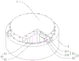
fig. 10 is a schematic view of a support-free fully precast floor slab provided in example 4 of the present application;
fig. 11 is a schematic view of a state of a support-free fully precast floor slab provided in example 5 of the present application.
Description of reference numerals: 1. fully prefabricating a floor slab body by using concrete; 2. a bracket; 21. a support member; 211. a vertical steel plate; 212. horizontally placing a steel plate; 22. a shear resistant member; 3. a wall body; 4. a reinforcing mesh; 41. transverse reinforcing steel bars; 42. longitudinal reinforcing steel bars.
Detailed Description
The present application is described in further detail below with reference to the accompanying drawings.
The embodiment of the application discloses take prefabricated floor of exempting from to support of bracket.
Example 1
Referring to fig. 1, the support-free precast floor slab with the bracket is a full precast floor slab, and comprises a concrete full precast floor slab body 1 and a plurality of brackets 2, wherein the meaning of the concrete full precast floor slab body 1 is a concrete floor slab with the bracket 2 removed, the pouring operation is completed in advance before the assembly type building construction operation, the bracket 2 is buried in the concrete in the pouring operation process, and the bracket 2 is precast and molded before the pouring construction operation of the concrete full precast floor slab body 1. The bracket 2 and the prefabricated floor slab are both prepared by adopting standardized module operation, so that the field wet operation and the template engineering quantity are greatly reduced.
Referring to fig. 2, two groups of corbels 2 are respectively arranged on two side walls of a concrete full-precast floor slab body 1 in the span direction (transverse direction in fig. 1), each group includes two corbels 2, and each group may include more than three corbels 2 based on actual design requirements; when the full precast concrete floor slab body 1 is in the construction of pouring, its inside thickness based on building design standard and floor self inlays establishes one deck or two-layer reinforcing bar net 4, and two-layer reinforcing bar net 4 about the full precast concrete floor slab body 1 is embedded to be equipped with in this scheme. The reinforcing mesh 4 can be a prefabricated reinforcing mesh commonly used in the field of buildings and is generally formed by mutually and vertically and crossly welding, binding or connecting a plurality of longitudinal reinforcing steel bars 41 and a plurality of transverse reinforcing steel bars 42 through connecting pieces, and the distance between every two transverse reinforcing steel bars 41 and the distance between every two longitudinal reinforcing steel bars 42 are both 150-200 mm; the bracket 2 is anchored in the concrete fully-prefabricated floor slab body 1, the parts are all in a fishbone structure, the fishbone structure is coupled between two layers of reinforcing mesh 4, the upper layer of reinforcing mesh 4, the fishbone structure and the lower layer of reinforcing mesh 4 are coupled in concrete and are connected with the concrete to form a whole, the bottom of the part of the bracket 2 extending out of the concrete fully-prefabricated floor slab body 1 is provided with a supporting surface, and the floor slab is supported on a structural beam or a wall body through the supporting surface.
The fish bone structure adopts the steel construction that the machine tooling prepared formed for by shaped steel, steel sheet and reinforcing bar in this scheme an embodiment, and the fish bone structure can also pour fashioned component for adopting high strength material in other embodiments of this scheme. The corbel 2 comprises a supporting piece 21 and a shearing resistant piece 22, the supporting piece 21 comprises a vertical steel plate 211 and a horizontal steel plate 212, in a specific embodiment, the vertical steel plate 211 is made of I-shaped steel, the length direction of the I-shaped steel is transversely arranged along the span direction of the floor slab, and a part of the I-shaped steel is embedded in the floor slab; the shear resistant member 22 is made of reinforcing steel bars, a plurality of reinforcing steel bars are welded on a web plate of the I-shaped steel embedding part, and the plurality of reinforcing steel bars are arranged at intervals along the length direction of the I-shaped steel and are distributed in a mirror image mode by taking the web plate as a symmetrical surface. The reinforcing steel bars are linear and vertical to the web plates, and refer to fig. 3, 4 and 5, so that the reinforcing steel bars are simple in structure and easy to prepare.
In other embodiments, the shear pieces 22 are standard pieces such as shear studs or PBL (p-bonded Strips, PBL for short) shear keys, a plurality of holes penetrating through the thickness direction are formed in the middle of the i-steel web along the length direction, the shear pieces 22 are respectively and directly inserted into the through holes, the axial direction of the shear pieces 22 is perpendicular to the i-steel web, and finally the shear pieces 22 and the web are welded along the through holes to complete the prefabrication of the corbel 2. This scheme is higher for the welding process precision, can guarantee the angle of reinforcing bar and web is perpendicular and the interval between the adjacent reinforcing bar.
In order to improve the bearing stability of the support-free floor slab, the bottom of the vertical steel plate 211 is fixedly connected with the horizontal steel plate 212, in the above embodiment, a horizontal steel plate can be welded on the lower flange of the i-steel, and the bottom surface of the horizontal steel plate forms a supporting surface, so that the area of the horizontal steel plate is greatly increased relative to the area of the lower flange of the i-steel, and the bearing stability of the support 21 is improved. In order to avoid interference between the horizontal steel plates and the portions of the transverse steel bars 42 of the reinforcing mesh 4 extending out of the floor slab body, the width of each horizontal steel plate is smaller than the distance between two adjacent transverse steel bars 42.
Referring again to fig. 5, the flat steel plate 212 is a horizontally disposed rectangular plate. The lower edge of the part of the vertical steel plate 211 extending out of the concrete full precast floor slab body 1 is welded with the upper surface of the horizontal steel plate 212. The horizontal steel plates 212 are perpendicular to the vertical steel plates 211. In order to avoid interference with the lower layer reinforcing mesh 4, the bottom of the part of the vertical steel plate 211 embedded in the floor slab is provided with a gap, the part of the vertical steel plate 211 extending out of the floor slab extends downwards, the lower edge of the extending part is welded on the horizontal steel plate 212, and the lower surface of the horizontal steel plate 212 is flush with the lower surface of the concrete full-precast floor slab body 1. The lower surface of the flat steel plate 212 abuts against the upper surface of the structural beam or wall 3.
In other embodiments of the present disclosure, the lower surface of the vertical steel plate 211 extending out of the concrete fully-precast floor slab body 1 extends to two sides to form the supporting surface and is flush with the lower surface of the concrete fully-precast floor slab body 1.
The vertical steel plate 211 mainly bears the dead weight of the floor slab body, the vertical structure of the vertical steel plate 211 can enhance the bearing performance of the connecting node, the lower surface of the part, extending out of the concrete fully-prefabricated floor slab body 1, of the vertical steel plate 211 forms a supporting surface towards the surfaces extending towards the two sides of the vertical steel plate 211 or the bottom surface of the horizontally-arranged steel plate 212 connected with the vertical steel plate and is attached to the upper surface of a structural beam or a wall 3 supporting the floor slab, and the increase of the contact area is favorable for improving the stability of the bracket steel structure in the construction process; the supporting surface is flush with the lower surface of the concrete fully-prefabricated floor slab body 1, so that the lower surface of the concrete fully-prefabricated floor slab body 1 and the upper surface of the structural beam or the wall 3 are at the same height, and when cement is poured into a joint space defined by the structural beam or the wall 3 and two adjacent concrete fully-prefabricated floor slab bodies, the construction quality reduction and the construction inconvenience caused by cement leakage are reduced; after the construction of the joints is completed, the overhanging reinforcing steel bars of the floor slab comprise transverse reinforcing steel bars 42, longitudinal reinforcing steel bars 41, the part of the corbel 2 extending out of the floor slab comprises a horizontal steel plate 212, and part of the vertical steel plate 211 is anchored in Concrete.
Before concrete full precast floor slab body 1 pours, to the demand of different shapes, can arrange prefabricated fashioned bracket 2 in the corresponding position in span direction's lateral wall, the preparation of support-free precast floor slab is accomplished to the concreting, the bracket structure can adopt unified standard based on the specification of floor, and prefabricate and install the shaping or through pouring integrated into one piece through machining before the construction, only need in the installation with its whole installation in place in floor slab pouring template, can implement and pour, construction efficiency can not consequently be reduced for ordinary precast floor slab's construction.
During floor slab prefabrication construction, firstly, pouring a layer of concrete in an installed forming die, then placing a reinforcing mesh 4 at the lower layer and pouring the concrete, and then respectively placing the four prefabricated brackets 2 at preset positions on two transverse sides and pouring the concrete; then placing the reinforcing mesh 4 on the upper layer, pouring concrete, grinding and curing to form, and finishing the preparation of the support-free fully-prefabricated floor slab;
referring to fig. 6, when assembling the support-free fully-prefabricated floor slab, two sides of the floor slab in the span direction support the concrete fully-prefabricated floor slab body 1 on the structural beam or the wall 3 through two brackets 2. The structural beam or wall 3 may be a concrete structure or a steel structure such as a load-bearing wall, a load-bearing beam column, etc. When pouring of connecting nodes between adjacent floor slabs and structural beams or walls 3 in the span direction is implemented; construction space is spacious relatively, has saved and has built full hall scaffold and in a large amount of dismouting work after the construction is accomplished, has promoted the efficiency of construction greatly, has shortened construction cycle, is favorable to assembly type structure's popularization and application.
In addition, the structure of the support-free full precast floor slab with the bracket is suitable for the full precast floor slab, and also comprises partial precast floor slabs such as partial composite floor slabs or composite floor slabs.
Referring to fig. 2, the width (parallel direction to the longitudinal steel bar 41) of the horizontal steel plate 212 is between 100 and 150 mm. Avoiding interference between the flat steel plate 212 and the transverse reinforcing bars 42.
A section of the vertical steel plate 211 in the concrete full precast floor slab body 1 is horizontally welded with a shear resistant member 22, and the shear resistant member 22 is a shear resistant connecting member. The shear pieces 22 vertically penetrate through the side wall of the vertical steel plate 211, and the lengths of the shear pieces 22 on the two sides of the vertical steel plate 211 are the same. When in pouring, the shearing resistant pieces 22 and the concrete full-precast floor slab body 1 are poured in the concrete full-precast floor slab body 1 together; the longitudinal movement of the vertical steel plates 211 is restricted by the shear blocks 22. Three shear pieces 22 are uniformly arranged along the length direction of the vertical steel plate 211. The number of the shear blocks 22 is designed and determined according to the load calculated from the size and specification of the prefabricated floor panel to improve the shear performance. The shear member 22 in this application includes shear members such as shear studs, PBL shear keys, shear bars, etc.
The implementation principle of the embodiment is as follows: when the floor slab is prefabricated, a proper amount of cement is injected into the mould; putting the lower layer reinforcing mesh 4 and injecting a proper amount of cement; and (3) putting the bracket 2 into the mould, and attaching the bottom surface of the bracket 2 to the ground of the mould. Pouring cement to submerge the corbels 2, putting the reinforcing mesh 4 on the upper layer, and continuously pouring the reinforcing mesh 4 on the upper layer submerged by the cement. And (5) waiting for cement solidification, and finishing prefabricating the concrete full-prefabricated floor slab body 1.
During construction, the floor slabs are lifted, so that the four brackets 2 on the two sides are respectively arranged on the structural beams or the wall bodies 3 on the two sides, after the two floor slabs are adjacently lifted in place (the adjacent sides are supported on the same structural beam or the wall body 3), cement is poured into a space formed by the two adjacent sides of the floor slabs and the structural beam or the wall body 3 between the two adjacent sides, and construction of the connection node is completed.
Example 2
Referring to fig. 7, the present embodiment is different from embodiment 1 in that a section of the bottom surface of the vertical steel plate 211 extending out of the concrete prefabricated floor slab body 1 is eliminated, and the upper surface of the horizontal steel plate 212 is higher than the lower surface of the vertical steel plate 211. The shear 22 is screwed with the vertical steel plate 211 through the through hole. The both sides wall of concrete prefabricated floor body 1 and the lateral wall butt of structural beam or wall body 3, the seal is better, and cement leakage when preventing to pour cement. The shear blocks 22 may be rectangular posts. Accordingly, by processing a rectangular through hole in the vertical steel plate 211, the shear block 22 is prevented from rotating relative to the vertical steel plate 211 during the cement pouring process, and the combination between the rectangular column and the solidified concrete is firmer.
Referring to fig. 8, as a modification of embodiment 2, the shear resistant member 22 may be a steel bar, and the steel bar is disposed at an end far from the connecting vertical steel plate 211 and has a ring shape (e.g., a rectangular closed ring or a circular closed ring) or a curved shape (e.g., an S shape, a semicircular shape, etc.) to increase an area of the steel bar embedded in the concrete and improve anchoring performance between the steel bar and the concrete.
Example 3
Referring to fig. 9, the present embodiment is different from embodiment 1 in that an angle between the shear 22 and the vertical steel plate is 60 °.
The shear pieces 22 are welded to one side of the vertical steel plate 211, and the shear pieces 22 gradually incline horizontally towards the direction of the horizontal steel plate 212 in the direction away from the vertical steel plate 211. The shear pieces 22 are obliquely arranged, namely the direction of the shear pieces 22 separated from the vertical steel plate 211 is an acute angle larger than 45 degrees, the shear pieces 22 are symmetrical on two sides of the vertical steel plate 211, the left side and the right side of the shear pieces 22 bear the same force when bearing the force, and the influence of non-uniform stress on the shear performance is avoided. The number of the shear pieces 22 is reasonably arranged as required, and the cost is saved while the vertical steel plate 211 is fixed. The structure enclosed by the adjacent shearing resistant pieces 22 and the vertical steel plates 211 positioned between the adjacent shearing resistant pieces 22 and the concrete filled in the structural space can be effectively connected into a whole, so that the anchoring stability of the reinforced concrete joint section is improved.
The bracket 2 is evenly provided with three along the length direction of the concrete full precast floor slab body 1 near one side of the building body 3. A plurality of brackets 2 support the concrete full precast floor slab body 1, and the support is more stable.
As a modification of embodiment 3, the shear 22 is made of arc-shaped steel bars, the arc-shaped steel bars are arranged along a horizontal plane, and the arc-shaped steel bars are gradually bent toward the interior of the floor slab from one end close to the side surface of the vertical steel plate 211 to one end far away from the side surface of the vertical steel plate 211, so that stress concentration at the joint of the shear 22 and the vertical steel plate 211 is reduced compared with embodiment 3. In other embodiments, the arc-shaped steel bars are gradually bent outward, upward and/or downward from the end close to the side of the vertical steel plate 211 to the end far away from the side of the vertical steel plate 211, and a plurality of arc-shaped steel bars connected to the vertical steel bar 211 can be twisted relatively on different planes to jointly enclose and form a space structure, so that the concrete in the enclosed space is anchored together, and the connection performance of the steel bars and the concrete can be further improved relative to the plane structure.
Example 4
Referring to fig. 10, the present embodiment is different from embodiment 1 in that the concrete precast floor slab body 1 is a triangular steel plate. The lateral wall of the concrete full precast floor slab body 1 is provided with brackets 2. Each side wall of the triangle is provided with a bracket 2 which plays a supporting role for the concrete fully-prefabricated floor slab body 1. The shear resistant member 22 is a shaft member with a cross-shaped cross section. The cross-shaped structure has larger bearing capacity in the transverse and longitudinal directions, and the shearing resistance of the shearing resistant part 22 is improved.
The implementation principle of the embodiment is as follows: during construction, the concrete fully-prefabricated floor slab body 1 is lifted, the concrete fully-prefabricated floor slab body 1 is moved to the position above the structural beam or the wall body 3, the concrete fully-prefabricated floor slab body 1 is descended, and the supporting device on the concrete fully-prefabricated floor slab body 1 is aligned with the structural beam or the wall body 3. And continuously descending the concrete full-precast floor slab body 1 to enable the horizontally arranged steel plate 212 to be in contact with the upper surface of the structural beam or the wall body 3. And pouring cement in a space formed by the upper surface of the structural beam or the wall body 3 and the side walls of the two concrete fully-prefabricated floor slab bodies 1 on the upper surface of the structural beam or the wall body to complete the connection of the nodes between the floor slab and the structural beam or the wall body 3.
Example 5
Referring to fig. 11, the present embodiment is different from embodiment 1 in that the concrete precast floor slab body 1 is a circular disc-shaped steel plate. The periphery wall of the concrete full precast floor slab body 1 is evenly provided with three brackets 2. When the concrete full precast floor slab body 1 is round, the brackets 2 are uniformly arranged on the peripheral wall to play a role of stable support.
The part of the vertical steel plate 211 extending downwards is eliminated, and the lower surface of the horizontal steel plate 212 and the lower surface of the vertical steel plate 211 extending out of one section of the concrete full precast floor slab body 1 are welded. The vertical steel plate 211 is rectangular, and is convenient to process or purchase.
Gaps are formed between the horizontal steel plates 212 and the reinforcing mesh 4 on the upper layer and between the horizontal steel plates and the reinforcing mesh 4 on the lower layer, and cement is filled in the gaps to increase the contact area of the steel and concrete.
The shear members 22 are horizontally disposed or vertically disposed webs. Fig. 11 shows a horizontal plate, the shear resistant member 22 is a rectangular plate, and the vertical plate is beneficial to improving the bearing performance and the shear resistant performance.
As a modification of example 5, the shear 22 employs a vertical steel plate perpendicular to the vertical steel plate 211; the vertical steel plate is a right triangle, one of the right angle edges is fixedly connected with the vertical steel plate side wall, the other right angle edge is close to the top of the vertical steel plate 211 and extends towards the direction far away from the vertical steel plate 211 side wall, and the inclined edge is in a transition curve shape and is sunken towards the near right angle end. Triangle-shaped can promote the stability of structure, strengthens the connection performance between vertical steel sheet 211 and the shear 22, and the transition curve shape of depressed part has reduced vertical steel sheet 211 and shear 22 junction because of stress concentration produces the possibility of destruction.
The above embodiments are preferred embodiments of the present application, and the protection scope of the present application is not limited by the above embodiments, so: all equivalent changes made according to the structure, shape and principle of the present application shall be covered by the protection scope of the present application.
Claims (9)
1. The utility model provides a take support-free precast floor slab of bracket, includes the full precast floor slab body of concrete, its characterized in that still includes:
the brackets are arranged on two sides of the concrete full-precast floor slab body in the span direction; every the bracket anchor in this internal part of full prefabricated floor of concrete all is the fishbone structure, stretches out this external partial bottom of full prefabricated floor of concrete all is formed with the holding surface.
2. The braceless precast floor slab with brackets according to claim 1, wherein at least one layer of reinforcing mesh is laid inside the concrete full precast floor slab body;
each bracket is provided with a gap between the part of the concrete full precast floor slab body and the reinforcing mesh;
the reinforcing mesh is formed by cross-connecting a plurality of transverse reinforcing steel bars and a plurality of longitudinal reinforcing steel bars according to a preset interval; two ends of the transverse steel bar and the longitudinal steel bar respectively extend outwards from the side surface of the concrete precast floor slab body;
and the part of each bracket extending out of the concrete full-precast floor slab body is positioned between two adjacent transverse steel bars or between two adjacent longitudinal steel bars.
3. The braceless precast floor slab with brackets according to claim 2, characterized in that two layers of steel bar nets are arranged in the concrete full precast floor slab body;
the bracket is located the whole internal part of prefabricated floor of concrete and is located between two-layer reinforcing bar net, and all fill between two-layer reinforcing bar net and have the concrete.
4. A support-free precast floor slab with corbels according to claim 2 or 3, wherein the corbels each comprise:
the vertical steel plate is in a long strip shape to form a spine of the fishbone structure, one end of the vertical steel plate is anchored in the concrete fully-prefabricated floor body, and the other end of the vertical steel plate extends out of the concrete fully-prefabricated floor body along the length direction of the transverse steel bar or the longitudinal steel bar;
the top surface of the horizontal steel plate is fixedly connected with the part of the vertical steel plate extending out of the concrete full-prefabricated floor body, and the bottom surface of the horizontal steel plate forms the supporting surface;
the shearing resistant pieces are anchored in the concrete fully-prefabricated floor body and distributed on two sides of the vertical steel plate to form ribs of the fishbone structure; one end of the vertical steel plate is fixed on the vertical side face of the part of the vertical steel plate in the concrete full-prefabricated floor body, and the other end of the vertical steel plate extends towards the direction deviating from the vertical side face.
5. The braceless precast floor slab with brackets according to claim 4, wherein a plurality of the shear blocks are arranged at intervals along the length direction of the vertical steel plates.
6. The braceless precast floor slab of claim 5 wherein the shear blocks comprise shear studs or PBL shear keys; the shear stud or the PBL shear key is a linear shaft component; the included angle between the shear piece and the vertical steel plate is 45-90 degrees.
7. The support-free precast floor slab with bracket according to claim 5, wherein the shear resistant member is connected to the thickness direction of the vertical steel plate and fixed with the vertical steel plate.
8. The support-free precast floor slab with bracket according to claim 5, wherein the shear resistant member is a curved shaft member; the shear piece is gradually bent from one end close to the vertical steel plate to one end far away from the vertical steel plate.
9. The braceless precast floor slab with brackets according to the ring claim 5, characterized in that the shear comprises vertical steel plates perpendicular to the vertical steel plates;
the vertical steel plate is in the shape of a right triangle, one of the right-angled edges is fixedly connected with the vertical steel plate side wall, the other right-angled edge is close to the top of the vertical steel plate and extends towards the direction far away from the vertical steel plate side wall, and the bevel edge is in a transition curve shape and is sunken towards the near right-angled end.
Priority Applications (1)
| Application Number | Priority Date | Filing Date | Title |
|---|---|---|---|
| CN202110286221.XA CN113027021A (en) | 2021-03-17 | 2021-03-17 | Support-free prefabricated floor slab with bracket |
Applications Claiming Priority (1)
| Application Number | Priority Date | Filing Date | Title |
|---|---|---|---|
| CN202110286221.XA CN113027021A (en) | 2021-03-17 | 2021-03-17 | Support-free prefabricated floor slab with bracket |
Publications (1)
| Publication Number | Publication Date |
|---|---|
| CN113027021A true CN113027021A (en) | 2021-06-25 |
Family
ID=76471294
Family Applications (1)
| Application Number | Title | Priority Date | Filing Date |
|---|---|---|---|
| CN202110286221.XA Pending CN113027021A (en) | 2021-03-17 | 2021-03-17 | Support-free prefabricated floor slab with bracket |
Country Status (1)
| Country | Link |
|---|---|
| CN (1) | CN113027021A (en) |
Cited By (2)
| Publication number | Priority date | Publication date | Assignee | Title |
|---|---|---|---|---|
| CN113818578A (en) * | 2021-09-18 | 2021-12-21 | 北京市建筑设计研究院有限公司 | Induced seam structure with prefabricated connecting piece |
| CN114856030A (en) * | 2022-06-08 | 2022-08-05 | 青岛中科坤泰装配建筑科技有限公司 | Prefabricated side wall board and prefabricated plate's connected node |
Citations (4)
| Publication number | Priority date | Publication date | Assignee | Title |
|---|---|---|---|---|
| CN107829515A (en) * | 2017-11-23 | 2018-03-23 | 厦门华旸建筑工程设计有限公司 | The construction method that a kind of new precast panel and prefabricated board are connected with beam |
| CN109680835A (en) * | 2019-02-15 | 2019-04-26 | 姚攀峰 | A kind of self-bearing type precast concrete wall panel, concrete walls, structural system and engineering method |
| CN110439122A (en) * | 2019-08-21 | 2019-11-12 | 沈阳建筑大学 | A kind of precast floor slab and H profile steel beam connecting structure and connection method |
| CN112502339A (en) * | 2020-12-07 | 2021-03-16 | 上海市机械施工集团有限公司 | Prefabricated coincide floor and connection structure with support girder steel thereof |
-
2021
- 2021-03-17 CN CN202110286221.XA patent/CN113027021A/en active Pending
Patent Citations (4)
| Publication number | Priority date | Publication date | Assignee | Title |
|---|---|---|---|---|
| CN107829515A (en) * | 2017-11-23 | 2018-03-23 | 厦门华旸建筑工程设计有限公司 | The construction method that a kind of new precast panel and prefabricated board are connected with beam |
| CN109680835A (en) * | 2019-02-15 | 2019-04-26 | 姚攀峰 | A kind of self-bearing type precast concrete wall panel, concrete walls, structural system and engineering method |
| CN110439122A (en) * | 2019-08-21 | 2019-11-12 | 沈阳建筑大学 | A kind of precast floor slab and H profile steel beam connecting structure and connection method |
| CN112502339A (en) * | 2020-12-07 | 2021-03-16 | 上海市机械施工集团有限公司 | Prefabricated coincide floor and connection structure with support girder steel thereof |
Cited By (3)
| Publication number | Priority date | Publication date | Assignee | Title |
|---|---|---|---|---|
| CN113818578A (en) * | 2021-09-18 | 2021-12-21 | 北京市建筑设计研究院有限公司 | Induced seam structure with prefabricated connecting piece |
| CN113818578B (en) * | 2021-09-18 | 2023-04-18 | 北京市建筑设计研究院有限公司 | Induced seam structure with prefabricated connecting piece |
| CN114856030A (en) * | 2022-06-08 | 2022-08-05 | 青岛中科坤泰装配建筑科技有限公司 | Prefabricated side wall board and prefabricated plate's connected node |
Similar Documents
| Publication | Publication Date | Title |
|---|---|---|
| CN101487332B (en) | Prefabricated hollow superposed beam, and cast-in-situ construction method for beam and precast slab | |
| CN109680835B (en) | Self-supporting precast concrete wallboard, concrete wall, structural system and construction method | |
| CN207110167U (en) | One kind assembling flat close rib building roof of superposed type two dimension prestressing | |
| CN108301545A (en) | A kind of big module overlapping contignation of the assembled with space truss temporary support | |
| CN113027021A (en) | Support-free prefabricated floor slab with bracket | |
| CN111851825A (en) | Fabricated form-removal-free prefabricated steel bar truss floor and construction method thereof | |
| CN107905426B (en) | Construction method of bidirectional hollow composite floor slab | |
| CN109469204A (en) | Assembled steel reinforced concrete combination frame structure and construction method based on composite beam | |
| CN208328647U (en) | A kind of durable lower flange hollow slab bridge of the quick prefabricated assembled light in city | |
| CN214884632U (en) | Assembled shaped steel composite wall | |
| CN208309388U (en) | The underwater bearing platform construction structure integrally transferred | |
| CN105952044B (en) | A kind of full precast prestressed concrete floor construction and prestressing force assembly method | |
| CN212534738U (en) | Truss floor plate | |
| CN212926589U (en) | Assembly type formwork-dismantling-free structural body formwork and cast-in-place formwork-dismantling-free structural body | |
| CN212802185U (en) | Prefabricated steel bar truss floor of assembled form removal-free | |
| CN112282164B (en) | Light composite floor slab structure and construction method thereof | |
| CN114753482A (en) | Assembled rectangular pool | |
| CN210289267U (en) | Assembled platform canopy | |
| CN112064824A (en) | Combined-connection prefabricated shear wall system | |
| CN112982771A (en) | Fully-prefabricated lattice type reinforced concrete support-free floor and manufacturing method thereof | |
| CN113323262A (en) | 3D printed prefabricated wall module, wall and construction method of wall | |
| CN111851804A (en) | Assembly type formwork-dismantling-free structural body formwork and cast-in-place formwork-dismantling-free structural body | |
| CN112227580A (en) | Steel pipe truss prestressed hollow superimposed sheet | |
| CN206591624U (en) | A kind of prefabricated PC concrete overlaps groove type plate sheet-pile composite frame structure | |
| CN111663695A (en) | Assembly type template-free box-type floor system and construction process thereof |
Legal Events
| Date | Code | Title | Description |
|---|---|---|---|
| PB01 | Publication | ||
| PB01 | Publication | ||
| SE01 | Entry into force of request for substantive examination | ||
| SE01 | Entry into force of request for substantive examination | ||
| RJ01 | Rejection of invention patent application after publication | ||
| RJ01 | Rejection of invention patent application after publication |
Application publication date: 20210625 |