CN113018917A - Rotary type efficient particle separation device and use method - Google Patents
Rotary type efficient particle separation device and use method Download PDFInfo
- Publication number
- CN113018917A CN113018917A CN202110225705.3A CN202110225705A CN113018917A CN 113018917 A CN113018917 A CN 113018917A CN 202110225705 A CN202110225705 A CN 202110225705A CN 113018917 A CN113018917 A CN 113018917A
- Authority
- CN
- China
- Prior art keywords
- rotary
- shell
- tracks
- particles
- water
- Prior art date
- Legal status (The legal status is an assumption and is not a legal conclusion. Google has not performed a legal analysis and makes no representation as to the accuracy of the status listed.)
- Pending
Links
Images
Classifications
-
- B—PERFORMING OPERATIONS; TRANSPORTING
- B01—PHYSICAL OR CHEMICAL PROCESSES OR APPARATUS IN GENERAL
- B01D—SEPARATION
- B01D21/00—Separation of suspended solid particles from liquids by sedimentation
- B01D21/02—Settling tanks with single outlets for the separated liquid
- B01D21/04—Settling tanks with single outlets for the separated liquid with moving scrapers
- B01D21/06—Settling tanks with single outlets for the separated liquid with moving scrapers with rotating scrapers
-
- B—PERFORMING OPERATIONS; TRANSPORTING
- B01—PHYSICAL OR CHEMICAL PROCESSES OR APPARATUS IN GENERAL
- B01D—SEPARATION
- B01D21/00—Separation of suspended solid particles from liquids by sedimentation
- B01D21/18—Construction of the scrapers or the driving mechanisms for settling tanks
-
- B—PERFORMING OPERATIONS; TRANSPORTING
- B01—PHYSICAL OR CHEMICAL PROCESSES OR APPARATUS IN GENERAL
- B01D—SEPARATION
- B01D21/00—Separation of suspended solid particles from liquids by sedimentation
- B01D21/18—Construction of the scrapers or the driving mechanisms for settling tanks
- B01D21/183—Construction of the scrapers or the driving mechanisms for settling tanks with multiple scraping mechanisms
-
- B—PERFORMING OPERATIONS; TRANSPORTING
- B01—PHYSICAL OR CHEMICAL PROCESSES OR APPARATUS IN GENERAL
- B01D—SEPARATION
- B01D21/00—Separation of suspended solid particles from liquids by sedimentation
- B01D21/24—Feed or discharge mechanisms for settling tanks
- B01D21/2405—Feed mechanisms for settling tanks
-
- B—PERFORMING OPERATIONS; TRANSPORTING
- B01—PHYSICAL OR CHEMICAL PROCESSES OR APPARATUS IN GENERAL
- B01D—SEPARATION
- B01D21/00—Separation of suspended solid particles from liquids by sedimentation
- B01D21/24—Feed or discharge mechanisms for settling tanks
- B01D21/2444—Discharge mechanisms for the classified liquid
-
- B—PERFORMING OPERATIONS; TRANSPORTING
- B01—PHYSICAL OR CHEMICAL PROCESSES OR APPARATUS IN GENERAL
- B01D—SEPARATION
- B01D21/00—Separation of suspended solid particles from liquids by sedimentation
- B01D21/24—Feed or discharge mechanisms for settling tanks
- B01D21/245—Discharge mechanisms for the sediments
Landscapes
- Chemical & Material Sciences (AREA)
- Chemical Kinetics & Catalysis (AREA)
- Separation Of Solids By Using Liquids Or Pneumatic Power (AREA)
Abstract
The invention provides a rotary type high-efficiency particle separation device and a using method thereof, wherein the device comprises a shell, a water inlet positioned at one side of the shell, a free water distribution area positioned at one side of the water inlet, a plurality of water outlet grooves positioned at one side opposite to the water inlet, a plurality of rotary type crawler belts uniformly arranged in the shell, and a driving motor positioned at the front side outside the shell, wherein the water outlet groove is positioned between two adjacent rotary type crawler belts; the rotary track comprises a first bearing positioned at the front part of the shell, a driving shaft and a second bearing positioned at the rear part of the shell; the first bearings of two adjacent rotary tracks are connected through a driving chain, and a driving motor is connected with a driving shaft of one rotary track in the plurality of rotary tracks. The crawler of the device provided by the invention is a rotary crawler, so that the rising flow velocity of the dense-phase region is delayed, the separation efficiency of the dense-phase region is improved, and the rising flow velocity of the dilute-phase region is accelerated, so that the clear water after solid-liquid separation is accelerated to rise, and the space utilization rate between inclined plates is improved.
Description
Technical Field
The invention belongs to the technical field of sewage treatment, and particularly relates to a rotary type efficient particle separation device and a using method thereof.
Background
Classic fixed swash plate sedimentation tank utilizes the shallow layer principle of deposiing, sets up the multilayer baffle in the cell body and makes the separation efficiency of granule promote greatly. However, in actual use, in order to facilitate the particles deposited on the inclined plate to fall into the mud bucket, the angle of the inclined plate is usually set to be steeper, which greatly limits the treatment efficiency of the inclined plate sedimentation tank. And for particles with high adhesion, the particles are generally easy to adhere and deposit on the inclined plate, which causes large-area blockage of the water passage and seriously influences the production safety.
Disclosure of Invention
Aiming at the defects, the invention provides a rotary type high-efficiency particle separation device and a using method thereof, which are used for solving the problems of low treatment efficiency and large occupied area in a sewage biochemical treatment process.
The invention provides the following technical scheme: a rotary type efficient particle separating device comprises a shell, a water inlet, a free water distribution area, a plurality of water outlet grooves, a plurality of rotary type tracks and a driving motor, wherein the water inlet is positioned at one side of the shell, the free water distribution area is positioned at one side of the water inlet, the water outlet grooves are positioned at one side opposite to the water inlet, the rotary type tracks are uniformly arranged in the shell, the driving motor is positioned at the front side outside the shell, and the water outlet grooves are positioned between two adjacent rotary type tracks;
the rotary track comprises a first bearing positioned at the front part of the shell, a driving shaft and a second bearing positioned at the rear part of the shell; the first bearings of two adjacent rotary tracks are connected through a driving chain, and the driving motor is connected with a driving shaft of one rotary track in the plurality of rotary tracks.
Furthermore, a plurality of mud hoppers are arranged at the lower part of the free water distribution area of the device.
Further, the number of the rotary tracks is 7.
Further, the rotary track is provided with a mud scraper at the second bearing.
The invention also provides a using method of the rotary type high-efficiency particle separating device, which comprises the following steps:
1) the mixed liquid containing particles enters the shell from the water inlet, primary particle separation is carried out in the free water distribution area, large particles and heavy particles directly sink into the mud bucket, and the remaining muddy water continuously moves upwards to enter the efficient separation area for secondary separation by utilizing the shallow layer precipitation principle;
2) in the high-efficiency separation zone formed by the plurality of rotary tracks, a water body can be divided into a dense-phase zone and a dilute-phase zone which are close to the rotary tracks, the dense-phase zone is a separated particle phase zone, the dilute-phase zone is a separated clear water phase zone, the flow velocity at boundary layers on two sides is lower due to the retention phenomenon of flow channel boundaries, fluid is accelerated by arranging the rotary tracks, clear water in the dilute phase is accelerated to rise by utilizing the coanda effect of the fluid, and particles in the dense-phase zone are accelerated to fall;
3) after rising, the clear water in the dilute phase zone overflows from the water outlet tank to form water;
4) the particles in the dense-phase area directly fall into a bottom mud bucket;
5) the rotary tracks are driven by a first bearing with the upper part as a driving shaft, a second bearing as a driven shaft is arranged at the lower part, and after one of the rotary tracks is driven to rotate by a driving motor outside the shell, the first bearing of the driving shaft drives the other rotary tracks to rotate by the driving chain.
Further, in the step 4), when the particles have certain adhesiveness, the mud scraper on the rotating track scrapes the particles off the track, and the particles fall into the mud bucket at the bottom automatically after being gathered to a certain volume and weight.
Further, the apparatus has 7 revolving tracks, and 7 drive shafts share 1 drive motor.
The invention has the beneficial effects that:
1. the track of the rotary high-efficiency particle separating device provided by the invention is a rotary track, the rising flow velocity of a dense-phase area is delayed, the separation efficiency of the dense-phase area is improved, the rising flow velocity of a dilute-phase area is accelerated, and the clear water after solid-liquid separation is accelerated to rise, so that the space utilization rate between inclined plates is improved.
2. The rotary type high-efficiency particle separating device provided by the invention can adjust the rotating speed according to the actual water quality of inlet and outlet water. The angle of the inclined plate can be designed at will.
3. The bottom of the rotary track of the rotary efficient particle separating device provided by the invention is provided with the mud scraping fixed knife, so that sediment and adhered substances on the track can be scraped, and the treatment efficiency of the inclined plate is improved. The inclined plate sedimentation tank is suitable for separating viscous particles, and the application range of the inclined plate sedimentation tank is greatly expanded. Prevent the accumulated mud from blocking the ascending channel and improve the processing capacity.
4. The rotary efficient particle separation device provided by the invention can replace radial-flow, advection and other sedimentation tanks to be used for separating biochemical sludge, and greatly saves land resources in China.
Drawings
The invention will be described in more detail hereinafter on the basis of embodiments and with reference to the accompanying drawings. Wherein:
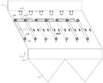
FIG. 1 is a schematic view of a rotary high-efficiency particle separator according to the present invention;
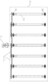
FIG. 2 is a side view of the rotary high-efficiency particle separator provided by the present invention.
Detailed description of the preferred embodiments
The technical solutions in the embodiments of the present invention will be clearly and completely described below with reference to the drawings in the embodiments of the present invention, and it is obvious that the described embodiments are only a part of the embodiments of the present invention, and not all of the embodiments. All other embodiments, which can be derived by a person skilled in the art from the embodiments given herein without making any creative effort, shall fall within the protection scope of the present invention.
Example 1
As shown in fig. 1-2, the rotary type high-efficiency particle separating device provided by the invention comprises a housing 1, a water inlet 2 located at one side of the housing, a free water distribution area 3 located at one side of the water inlet, a plurality of water outlet grooves 4 located at the opposite side of the water inlet, a plurality of rotary type caterpillar tracks 5 uniformly arranged in the housing 1, and a driving motor 6 located at the front side of the exterior of the housing 1, wherein the water outlet grooves 4 are located between two adjacent rotary type caterpillar tracks 5;
the rotary track 5 comprises a first bearing 5-1 at the front of the housing, a drive shaft 5-2 and a second bearing 5-3 at the rear of the housing; the first bearings 5-1 of two adjacent rotary tracks are connected through a driving chain 7, and a driving motor 8 is connected with a driving shaft 5-2 of one rotary track in the plurality of rotary tracks 5.
The lower part of the free water distribution area 3 of the device is provided with a plurality of mud hoppers 3-1.
The number of the rotary type caterpillar tracks 5 is 7, and the 7 driving shafts share 1 driving motor.
The rotary track 5 is provided with a mud scraper 5-4 at the second bearing 5-2.
Example 2
The embodiment adopts the use method of the rotary high-efficiency particle separation device provided by the embodiment 1, and comprises the following steps:
1) the mixed liquid containing particles enters the shell 1 from the water inlet 2, primary particle separation is carried out in the free water distribution area 3, large particles and heavy particles directly sink into the mud bucket, and the remaining muddy water continuously moves upwards to enter the efficient separation area for secondary separation by utilizing the shallow layer precipitation principle;
2) in the high-efficiency separation zone formed by a plurality of rotary tracks 5, a water body can be divided into a dense-phase zone and a dilute-phase zone which are close to the rotary tracks 5, the dense-phase zone is a separated particle phase zone, the dilute-phase zone is a separated clear water phase zone, because of the detention phenomenon of the flow channel boundary, the flow velocity at the boundary layers at two sides is generally lower, the fluid is accelerated by arranging the rotary tracks, the clear water in the dilute phase is accelerated to rise by utilizing the coanda wall effect of the fluid, the particles in the dense-phase zone are accelerated to fall, and the space utilization rate and the separation efficiency of the high-efficiency separation zone are greatly improved;
3) after rising, clear water in the dilute phase zone overflows from the water outlet tank 4;
4) the particles in the dense phase region directly fall into a bottom mud bucket, when the particles have certain adhesiveness, the mud scraper 5-4 on the rotary crawler 5 scrapes the particles off the crawler, and when the particles are gathered to a certain volume and weight, the particles automatically fall into the bottom mud bucket 3-1;
5) the rotary crawler belts 5 are driven by first bearings 5-1 with the upper parts as driving shafts, the lower parts are provided with second bearings 5-2 as driven shafts, and after one of the rotary crawler belts 5 is driven to rotate by a driving motor outside the shell, the first bearing 5-1 of the driving shaft drives the other rotary crawler belts 5 to rotate by a driving chain.
Comparative example 1
By adopting the use method provided by the embodiment 2, the mixed liquor of the biochemical pool of a certain domestic sewage treatment plant is adopted to carry out the particle separation comparison experiment, and the inclined plates of the 7-layer inclined plate particle separation device are 1 meter in length, 1 meter in width, 0.866 meter in height, 60 degrees in angle and 200mm in distance. The rotary high-efficiency particle separation device provided by the invention is adopted in the embodiment 2, the traditional classical fixed inclined plate precipitation device is adopted in the comparative example 1, and the effect after the operation for 3 months is shown in the table 2:
TABLE 1

Comparative example 2
By adopting the use method provided by the embodiment 2, the particle mixed liquid after coagulation and flocculation reaction of certain fluorine-containing sewage is adopted for carrying out separation comparison experiments, and the inclined plates of the 7-layer inclined plate particle separation device are 1 meter in length, 1 meter in width, 0.866 meter in height, 30 degrees in angle and 100mm in distance. The effect of the rotary high-efficiency particle separation device adopted in the example 2 and the traditional classical fixed inclined plate precipitation device adopted in the comparative example 2 after 3 months of operation is shown in the table 2:
TABLE 2

While the invention has been described with reference to a preferred embodiment, various modifications may be made and equivalents may be substituted for elements thereof without departing from the scope of the invention. In particular, the technical features mentioned in the embodiments can be combined in any way as long as there is no structural conflict. It is intended that the invention not be limited to the particular embodiments disclosed, but that the invention will include all embodiments falling within the scope of the appended claims.
Claims (7)
1. A rotary type efficient particle separation device is characterized by comprising a shell (1), a water inlet (2) positioned on one side of the shell, a free water distribution area (3) positioned on one side of the water inlet, a plurality of water outlet grooves (4) positioned on one side opposite to the water inlet, a plurality of rotary type crawler belts (5) uniformly arranged in the shell (1), and a driving motor (6) positioned on the front side of the outer portion of the shell (1), wherein the water outlet grooves (4) are positioned between two adjacent rotary type crawler belts (5);
the rotary track (5) comprises a first bearing (5-1) positioned at the front part of the shell, a driving shaft (5-2) and a second bearing (5-3) positioned at the rear part of the shell; the first bearings (5-1) of two adjacent rotary tracks are connected through a driving chain (7), and the driving motor (8) is connected with a driving shaft (5-2) of one rotary track in the rotary tracks (5).
2. The rotary high-efficiency particle separating device as claimed in claim 1, wherein a plurality of mud hoppers (3-1) are arranged at the lower part of the free water distribution area (3) of the device.
3. A rotary high efficiency particle separation apparatus as in claim 1, wherein the number of rotary tracks (5) is 7.
4. Rotary high efficiency particle separation apparatus according to claim 1, characterized by the fact that the rotary track (5) is provided with mud scraper (5-4) at the second bearing (5-2).
5. The use method of the rotary high-efficiency particle separating device as claimed in any one of claims 1 to 4, which comprises the following steps:
1) the mixed liquid containing particles enters the shell (1) from the water inlet (2), primary particle separation is carried out in the free water distribution area (3), large particles and heavy particles directly sink into the mud bucket, the remaining muddy water continuously moves upwards to enter the efficient separation area, and secondary separation is carried out by utilizing the shallow sedimentation principle;
2) in the high-efficiency separation zone formed by the plurality of rotary tracks (5), a water body can be divided into a dense-phase zone and a dilute-phase zone which are close to the rotary tracks (5), the dense-phase zone is a separated particle phase zone, the dilute-phase zone is a separated clear water phase zone, because of the detention phenomenon of the flow channel boundary, the flow velocity at the boundary layers at two sides is lower, the fluid is accelerated by arranging the rotary tracks, the clear water in the dilute phase is accelerated to rise by utilizing the coanda effect of the fluid, and the particles in the dense-phase zone are accelerated to fall;
3) after rising, the clear water in the dilute phase zone overflows from the water outlet tank (4) to discharge water;
4) the particles in the dense-phase area directly fall into a bottom mud bucket;
5) the rotary type caterpillar tracks (5) are driven by first bearings (5-1) with the upper parts serving as driving shafts, second bearings (5-2) serving as driven shafts are arranged at the lower parts, and after one of the rotary type caterpillar tracks (5) is driven to rotate by a driving motor outside the shell, the first bearings (5-1) of the driving shafts drive other rotary type caterpillar tracks (5) to rotate through the driving chains.
6. The use method of the rotary high-efficiency particle separating device in the claim 5 is characterized in that in the step 4), when the particles have certain adhesiveness, the mud scraper (5-4) on the rotary track (5) scrapes the particles off the track, and when the particles are gathered to certain volume and weight, the particles fall into the mud bucket (3-1) at the bottom.
7. The use method of the rotary high efficiency particle separator as in claim 5, wherein the device has 7 rotary tracks, and 7 drive shafts share 1 drive motor.
Priority Applications (1)
| Application Number | Priority Date | Filing Date | Title |
|---|---|---|---|
| CN202110225705.3A CN113018917A (en) | 2021-03-01 | 2021-03-01 | Rotary type efficient particle separation device and use method |
Applications Claiming Priority (1)
| Application Number | Priority Date | Filing Date | Title |
|---|---|---|---|
| CN202110225705.3A CN113018917A (en) | 2021-03-01 | 2021-03-01 | Rotary type efficient particle separation device and use method |
Publications (1)
| Publication Number | Publication Date |
|---|---|
| CN113018917A true CN113018917A (en) | 2021-06-25 |
Family
ID=76466301
Family Applications (1)
| Application Number | Title | Priority Date | Filing Date |
|---|---|---|---|
| CN202110225705.3A Pending CN113018917A (en) | 2021-03-01 | 2021-03-01 | Rotary type efficient particle separation device and use method |
Country Status (1)
| Country | Link |
|---|---|
| CN (1) | CN113018917A (en) |
Citations (3)
| Publication number | Priority date | Publication date | Assignee | Title |
|---|---|---|---|---|
| EP0596052A1 (en) * | 1992-04-15 | 1994-05-11 | Anton Felder | Method and inlet device for feeding flat sand traps and settling tanks. |
| KR101087672B1 (en) * | 2011-03-11 | 2011-11-30 | 주식회사 경호엔지니어링 종합건축사사무소 | Moving-belt type apparatus for preventing adherence sludge to settling pond |
| CN104254378A (en) * | 2012-02-02 | 2014-12-31 | 威埃姆集团股份有限公司 | Wastewater treatment plant |
-
2021
- 2021-03-01 CN CN202110225705.3A patent/CN113018917A/en active Pending
Patent Citations (3)
| Publication number | Priority date | Publication date | Assignee | Title |
|---|---|---|---|---|
| EP0596052A1 (en) * | 1992-04-15 | 1994-05-11 | Anton Felder | Method and inlet device for feeding flat sand traps and settling tanks. |
| KR101087672B1 (en) * | 2011-03-11 | 2011-11-30 | 주식회사 경호엔지니어링 종합건축사사무소 | Moving-belt type apparatus for preventing adherence sludge to settling pond |
| CN104254378A (en) * | 2012-02-02 | 2014-12-31 | 威埃姆集团股份有限公司 | Wastewater treatment plant |
Similar Documents
| Publication | Publication Date | Title |
|---|---|---|
| US20090095672A1 (en) | High efficiency grit removal system | |
| CN203653357U (en) | Air floater integrating cant board oil separation, cavitation and dissolved air floatation devices | |
| CN107233755A (en) | A kind of mobile sloping plate deposition wastewater treatment equipment | |
| CN109248475B (en) | Winding type sedimentation tank | |
| CN213803070U (en) | High-speed solid-liquid separation equipment of large-flow circulating granulation fluidized bed | |
| CN113521808A (en) | New process for treating tail water of tap water | |
| CN203389377U (en) | Suspending clarification device | |
| CN206081768U (en) | Sewage sedimentation tank | |
| CN202729923U (en) | Backflow type high-efficiency air-dissolved air flotation device | |
| CN113018917A (en) | Rotary type efficient particle separation device and use method | |
| CN112239256A (en) | High-speed solid-liquid separation equipment of large-flow circulating granulation fluidized bed | |
| CN108067358B (en) | Oil-water-sand separation three-phase horizontal spiral centrifuge | |
| CN216513030U (en) | Coagulating sedimentation tank device and sewage treatment system | |
| CN203281084U (en) | Anti-blocking precipitator | |
| CN211513534U (en) | A deposit device for sled dress formula integration sewage treatment unit | |
| CN213803069U (en) | Peripheral transmission type high-speed solid-liquid separation equipment for large-flow circulating granulation fluidized bed | |
| CN212050637U (en) | Oily waste water oil removal device | |
| CN211999167U (en) | Inclined tube precipitation device | |
| CN111617520B (en) | Turbulent flow sedimentation tank | |
| CN210711079U (en) | Pipeline cleaning sewage treatment device | |
| CN206483200U (en) | A kind of peripheral gear rack driven type mud scraper | |
| CN111544959A (en) | Silt multi-stage separation device | |
| CN214829242U (en) | Micro-sand circulating concentrator | |
| CN206229001U (en) | A kind of girt-water separation device | |
| CN116651063B (en) | Recovery equipment for epoxy resin preparation |
Legal Events
| Date | Code | Title | Description |
|---|---|---|---|
| PB01 | Publication | ||
| PB01 | Publication | ||
| SE01 | Entry into force of request for substantive examination | ||
| SE01 | Entry into force of request for substantive examination | ||
| RJ01 | Rejection of invention patent application after publication |
Application publication date: 20210625 |
|
| RJ01 | Rejection of invention patent application after publication |