CN113000249A - Paint spraying equipment capable of uniformly spraying inner and outer surfaces of mechanical part simultaneously - Google Patents
Paint spraying equipment capable of uniformly spraying inner and outer surfaces of mechanical part simultaneously Download PDFInfo
- Publication number
- CN113000249A CN113000249A CN202011394341.3A CN202011394341A CN113000249A CN 113000249 A CN113000249 A CN 113000249A CN 202011394341 A CN202011394341 A CN 202011394341A CN 113000249 A CN113000249 A CN 113000249A
- Authority
- CN
- China
- Prior art keywords
- paint
- pipeline
- fixedly connected
- paint spraying
- wall
- Prior art date
- Legal status (The legal status is an assumption and is not a legal conclusion. Google has not performed a legal analysis and makes no representation as to the accuracy of the status listed.)
- Withdrawn
Links
Images


Classifications
-
- B—PERFORMING OPERATIONS; TRANSPORTING
- B05—SPRAYING OR ATOMISING IN GENERAL; APPLYING FLUENT MATERIALS TO SURFACES, IN GENERAL
- B05B—SPRAYING APPARATUS; ATOMISING APPARATUS; NOZZLES
- B05B13/00—Machines or plants for applying liquids or other fluent materials to surfaces of objects or other work by spraying, not covered by groups B05B1/00 - B05B11/00
- B05B13/02—Means for supporting work; Arrangement or mounting of spray heads; Adaptation or arrangement of means for feeding work
- B05B13/0278—Arrangement or mounting of spray heads
-
- B—PERFORMING OPERATIONS; TRANSPORTING
- B05—SPRAYING OR ATOMISING IN GENERAL; APPLYING FLUENT MATERIALS TO SURFACES, IN GENERAL
- B05B—SPRAYING APPARATUS; ATOMISING APPARATUS; NOZZLES
- B05B13/00—Machines or plants for applying liquids or other fluent materials to surfaces of objects or other work by spraying, not covered by groups B05B1/00 - B05B11/00
- B05B13/02—Means for supporting work; Arrangement or mounting of spray heads; Adaptation or arrangement of means for feeding work
- B05B13/04—Means for supporting work; Arrangement or mounting of spray heads; Adaptation or arrangement of means for feeding work the spray heads being moved during spraying operation
- B05B13/0405—Means for supporting work; Arrangement or mounting of spray heads; Adaptation or arrangement of means for feeding work the spray heads being moved during spraying operation with reciprocating or oscillating spray heads
- B05B13/041—Means for supporting work; Arrangement or mounting of spray heads; Adaptation or arrangement of means for feeding work the spray heads being moved during spraying operation with reciprocating or oscillating spray heads with spray heads reciprocating along a straight line
-
- B—PERFORMING OPERATIONS; TRANSPORTING
- B05—SPRAYING OR ATOMISING IN GENERAL; APPLYING FLUENT MATERIALS TO SURFACES, IN GENERAL
- B05B—SPRAYING APPARATUS; ATOMISING APPARATUS; NOZZLES
- B05B13/00—Machines or plants for applying liquids or other fluent materials to surfaces of objects or other work by spraying, not covered by groups B05B1/00 - B05B11/00
- B05B13/02—Means for supporting work; Arrangement or mounting of spray heads; Adaptation or arrangement of means for feeding work
- B05B13/04—Means for supporting work; Arrangement or mounting of spray heads; Adaptation or arrangement of means for feeding work the spray heads being moved during spraying operation
- B05B13/0421—Means for supporting work; Arrangement or mounting of spray heads; Adaptation or arrangement of means for feeding work the spray heads being moved during spraying operation with rotating spray heads
-
- B—PERFORMING OPERATIONS; TRANSPORTING
- B05—SPRAYING OR ATOMISING IN GENERAL; APPLYING FLUENT MATERIALS TO SURFACES, IN GENERAL
- B05B—SPRAYING APPARATUS; ATOMISING APPARATUS; NOZZLES
- B05B13/00—Machines or plants for applying liquids or other fluent materials to surfaces of objects or other work by spraying, not covered by groups B05B1/00 - B05B11/00
- B05B13/06—Machines or plants for applying liquids or other fluent materials to surfaces of objects or other work by spraying, not covered by groups B05B1/00 - B05B11/00 specially designed for treating the inside of hollow bodies
- B05B13/0627—Arrangements of nozzles or spray heads specially adapted for treating the inside of hollow bodies
- B05B13/0636—Arrangements of nozzles or spray heads specially adapted for treating the inside of hollow bodies by means of rotatable spray heads or nozzles
-
- B—PERFORMING OPERATIONS; TRANSPORTING
- B05—SPRAYING OR ATOMISING IN GENERAL; APPLYING FLUENT MATERIALS TO SURFACES, IN GENERAL
- B05B—SPRAYING APPARATUS; ATOMISING APPARATUS; NOZZLES
- B05B15/00—Details of spraying plant or spraying apparatus not otherwise provided for; Accessories
- B05B15/60—Arrangements for mounting, supporting or holding spraying apparatus
- B05B15/68—Arrangements for adjusting the position of spray heads
Landscapes
- Spray Control Apparatus (AREA)
Abstract
The invention relates to the technical field of paint spraying equipment, in particular to paint spraying equipment capable of uniformly spraying the inner surface and the outer surface of a mechanical part simultaneously, which comprises a device main body, wherein the device main body comprises a paint spraying machine outer shell, the top end of the paint spraying machine outer shell is fixedly connected with a paint spraying cavity main body, the bottom end of the paint spraying cavity main body is fixedly connected with a main paint injection pipeline, the main paint injection pipeline is inserted into the paint spraying machine outer shell, the front end of the main paint injection pipeline is inserted with a control valve, the bottom end of the main paint injection pipeline is connected with a first paint injection pipeline through a bearing, and the bottom end of the first paint injection pipeline is connected with a second paint. The device can uniformly spray paint on parts with irregular shapes, the application range of the device is improved, and the reciprocating mechanism and the inner and outer double-layer simultaneous paint spraying mechanism are matched, so that the device can uniformly spray paint on the inner surface and the outer surface of mechanical parts with different shapes, and the paint spraying efficiency and the paint spraying effect are greatly improved.
Description
Technical Field
The invention relates to the technical field of paint spraying equipment, in particular to paint spraying equipment capable of uniformly spraying the inner surface and the outer surface of a mechanical part at the same time.
Background
Mechanical parts are also called mechanical elements and are inseparable single parts forming machines and machines, which are basic units of the machines, most of the mechanical parts are made of metal materials, meanwhile, in order to avoid the surfaces of the mechanical parts from being oxidized and ensure the service life of the mechanical parts, the surfaces of the mechanical parts are generally protected by paint spraying by spraying equipment, for example, a hardware part paint spraying device disclosed by the publication number CN105935639B solves the problem that the parts are manually placed when the parts are painted, is convenient for users to use, saves the paint spraying time, and is also convenient for users to use, for example, a cylindrical part paint spraying device disclosed by the publication number CN108787240B, when the paint spraying device is used, a cylindrical part to be painted is sleeved on the hollow column, the supporting plate on the hollow column plays a longitudinal supporting role for the cylindrical part, the supporting block on the side wall of the hollow column plays a transverse supporting role for the cylindrical part, the cylindrical part is firmly fixed on the hollow column, the position deviation of the cylindrical part in the rotating process is avoided, meanwhile, the paint spraying gun can longitudinally reciprocate through the linkage of the rotating rod, the rocker and the L-shaped rod, the cylindrical part sleeved on the hollow column can rotate through the connection relation of the worm, the worm wheel, the vertical rod and the hollow column, the side surface of the roller brush is attached to and fixed on the side surface of the cylindrical part, the roller brush can reversely rotate under the action of friction force between the roller brush and the cylindrical part, and in the process, the paint on the side surface of the cylindrical part is uniformly coated through the rotation of the roller brush, it can be seen that the paint spraying equipment which can uniformly spray the mechanical parts in the prior art substantially meets the use requirements of people, but the following problems still exist.
In order to ensure the service life of a part after production, generally, the surface of the part is protected by painting equipment, in order to improve the painting efficiency of the part, refer to the above-mentioned comparison patent with publication number CN105935639B, which improves the efficiency of the part during painting by arranging an electric telescopic rod and a clamping hand for clamping the part, but when painting, because part of the surface is shielded by a clamping device, the clamped part of the part after painting will have dead angle of painting, and the uniformity of the surface of the part cannot be ensured, and refer to the above-mentioned comparison patent with publication number CN108787240B, which supports the part by a hollow column, thereby ensuring the uniformity of painting on the outer surface of the part, but because part of the inside of the mechanical part is a through shape, the traditional painting equipment can not paint the inner surface of the part while painting on the outer surface of the mechanical part, greatly reduced the application scope and the spraying efficiency of device, and refer to above-mentioned two sets of comparison patents and know, two sets of patents can only support the cylindrical tube-shape thing of regular shape, can't carry out even spraying to the part of irregular shape, consequently need a paint spraying apparatus that can solve the problem that the interior outer surface of the mechanical parts of irregular shape carries out even spraying simultaneously to the interior outer surface of the mechanical parts of the traditional spraying equipment who provides simultaneously urgently.
Disclosure of Invention
The invention aims to provide paint spraying equipment capable of uniformly spraying inner and outer surfaces of mechanical parts at the same time, and aims to solve the problems that the traditional screening effect in the background technology is not ideal, and part of paddy is blown out along with empty paddy.
In order to achieve the purpose, the invention provides the following technical scheme: a paint spraying device capable of uniformly spraying the inner surface and the outer surface of a mechanical part simultaneously comprises a device main body, wherein the device main body comprises a paint spraying machine outer shell, the top end of the paint spraying machine outer shell is fixedly connected with a paint spraying cavity main body, the bottom end of the paint spraying cavity main body is fixedly connected with a main paint injection pipeline, the main paint injection pipeline is inserted into the paint spraying machine outer shell, the front end of the main paint injection pipeline is inserted with a control valve, a first paint injection pipeline bottom end bearing is connected with a first paint injection pipeline, the bottom end of the first paint injection pipeline is slidably connected with a second paint injection pipeline, a second paint injection pipeline outer wall bearing is connected with a lifting plate, the top end of the lifting plate is fixedly connected with a first output motor, the left end of the first output motor is fixedly connected with an output shaft, the left end of the output shaft is fixedly connected with a first conical gear, and the outer wall of the second bevel gear is meshed with the first bevel gear, a paint spraying mechanism is arranged below the second paint injection pipeline and comprises a first branch pipeline, the left side and the right side of the bottom end of the second paint injection pipeline are connected with the first branch pipeline through four-way pipe threads, one end of the first branch pipeline, which is far away from the second paint injection pipeline, is connected with a second branch pipeline through right-angle pipe threads, the inner sides of the two groups of second branch pipelines are connected with outer wall spray heads through threads, the bottom end of the second paint injection pipeline is connected with a third branch pipeline through four-way pipe threads, the left side and the right side of the third branch pipeline are connected with branch paint injection pipelines through three-way pipe threads, one ends of the two groups of branch paint injection pipelines, which are far away from the third branch pipeline, are connected with inner wall spray heads through threads, the outer wall of the third branch pipeline is connected with, and the reciprocating mechanism comprises second connecting rods, the left end bearing of the outer shell of the paint spraying machine is connected with two groups of second connecting rods, the outer walls of the second connecting rods are fixedly connected with first gears, two groups of the first gears are mutually meshed, the outer walls of the two groups of the second connecting rods are fixedly connected with second gears, the left end of the second connecting rod below is fixedly connected with a second output motor, and the bottom end of the second output motor is fixedly connected with a supporting base, the right end of the supporting base is fixedly connected with the outer shell of the paint spraying machine, the left end bearing of the outer shell of the paint spraying machine is connected with a third connecting rod, and the left end of the third connecting rod is fixedly connected with a third gear, the outer wall of the third gear is meshed with the second gear, the right end of the third connecting rod is fixedly connected with a fourth gear, the bottom end of the lifting plate is fixedly connected with a rack, and the front end of the rack is meshed with a fourth gear, and the outer wall of the third branch pipeline is provided with a supporting mechanism.
Preferably, a second sliding groove is formed in the first paint injection pipeline, a second sliding block is connected to the inner portion of the second sliding groove in a sliding mode, and one end, far away from the second sliding groove, of the second sliding block is fixedly connected to the second paint injection pipeline.
Preferably, a groove is formed in the bottom end of the first paint injection pipeline, a sealing gasket is fixedly connected to the inner wall of the groove, and the sealing gasket is made of rubber.
Preferably, the inner walls of the left side and the right side of the shell of the paint sprayer are provided with first sliding grooves, the first sliding grooves are connected with first sliding blocks in a sliding mode, and two groups of ends, far away from the first sliding grooves, of the first sliding blocks are fixedly connected to the lifting plate.
Preferably, a third sliding groove is formed in the fixing plate, two groups of third sliding blocks are connected to the inside of the third sliding groove in a sliding mode, one ends, far away from the third sliding groove, of the third sliding blocks are fixedly connected with first connecting rods, and one ends, far away from the third sliding blocks, of the first connecting rods are fixedly connected to the injection paint pipeline.
Preferably, the supporting mechanism comprises a threaded rod, the outer wall of the third branch pipeline is connected with the threaded rod in a bearing mode, the outer wall of the threaded rod is sleeved with a lantern ring, three groups of first hinge rods are hinged on the outer wall of the lantern ring, sleeves are hinged at one ends of the first hinge rods far away from the lantern ring, springs are fixedly connected on the inner walls of the three groups of sleeves, the other end of the spring is fixedly connected with a first connecting plate, the ends of the three groups of first connecting plates far away from the spring are fixedly connected with a fourth connecting rod, and the ends of the fourth connecting rods far away from the first connecting plates are all fixedly connected with second connecting plates, the ends of the three groups of second connecting plates far away from the fourth connecting rods are all fixedly connected with two groups of side plates, pulleys are connected between the two groups of side plates through rotating shafts, the fixed plate top articulates there are three groups of second articulated rods, three groups the one end that the fixed plate was kept away from to the second articulated rod all articulates in first articulated rod.
Preferably, the shape of the outer wall of the threaded rod and the shape of the inner wall of the lantern ring are both set to be threaded, and the shape of the outer wall of the threaded rod is matched with the shape of the inner wall of the lantern ring.
Preferably, three sets of the fourth spout has all been seted up to the sleeve inside, and the inside sliding connection that all has the fourth slider of fourth spout, three sets of the one end that the fourth spout was kept away from to the fourth slider is fixed connection in first connecting plate all.
Compared with the prior art, the invention has the beneficial effects that:
the paint spraying equipment capable of uniformly spraying the inner surface and the outer surface of a mechanical part simultaneously is provided with a paint spraying cavity main body, a main paint injection pipeline, a control valve, a first paint injection pipeline, a second paint injection pipeline, a first output motor, an output shaft, a first conical gear, a second conical gear, a first branch pipeline, a second branch pipeline, an outer wall spray head, a third branch pipeline, a branch paint injection pipeline, an inner wall spray head, a spraying piece, a second connecting rod, a first gear, a second output motor, a supporting base, a third connecting rod, a third gear, a fourth gear, a rack and a rotary control valve, wherein paint in the paint spraying cavity main body can be introduced into the first paint injection pipeline and the second paint injection pipeline through the main paint injection pipeline and then enters the second branch pipeline and the third branch pipeline through a four-way pipe, and paint in the third branch pipeline enters the branch paint injection pipeline through a three-way pipe, the paint vehicle in the branch paint injection pipeline and the second branch pipeline is sprayed out through the outer wall sprayer and the inner wall sprayer, the first output motor and the second output motor are started, the output shaft and the first bevel gear can be driven to rotate through the first output motor, the second bevel gear can be driven to rotate through the meshing of the first bevel gear and the second bevel gear, the second paint injection pipeline and the first paint injection pipeline can be driven to rotate through the second bevel gear, the third branch pipeline is driven to rotate simultaneously, the first branch pipeline, the second branch pipeline and the outer wall sprayer rotate periodically, the outer surface and the inner surface of a sprayed part can be sprayed simultaneously through the rotation of the outer wall sprayer and the inner wall sprayer, the uniform spraying effect of the device is ensured, the device can spray the inner surface and the outer surface of the sprayed part simultaneously, when the second output motor is started, the second connecting rod, the first gear and the second gear can be driven to rotate through the second output motor, meanwhile, due to the meshing of the two groups of first gears, the rotating directions of the two groups of first gears are opposite, meanwhile, the two groups of second gears rotate reversely, the third gear can rotate reversely after rotating in the forward direction through the two groups of second gears, so that the third gear and the fourth gear can rotate in the reciprocating forward and reverse directions, the rack can move in the up-and-down reciprocating mode through the meshing of the fourth gear and the rack, thereby driving the two groups of inner wall spray heads and the two groups of outer wall spray heads to move in the up-and-down reciprocating mode while rotating, through the mechanism, the inner surface and the outer surface of a sprayed part can be comprehensively and uniformly sprayed with paint, the problem that the inner surface of the part can not be sprayed with paint by the traditional paint spraying equipment is solved, and the reciprocating mechanism is matched, the device can perform up-and-down reciprocating type paint spraying on the sprayed part while performing rotary paint spraying on the inner surface and the outer surface of the sprayed part, namely, the inner surface and the outer surface of the sprayed part can be comprehensively and uniformly sprayed;
meanwhile, a threaded rod is arranged, a lantern ring, a first hinged rod, a sleeve, a spring, a first connecting plate, a fourth connecting rod, a second connecting plate, a side plate, a pulley and a second hinged rod are arranged, a fixed plate is held, then the threaded rod is rotated, the lantern ring can be driven to move downwards through threaded connection of the threaded rod and the lantern ring, so that the first hinged rod is driven to rotate, one end, far away from the lantern ring, of the first hinged rod rotates towards the direction of the lantern ring, so that the sleeve is driven, the fourth connecting rod and the second connecting plate move towards the direction of the lantern ring and are inserted into a spraying part, the threaded rod is rotated reversely, three groups of sleeves can be driven to move towards one end, far away from the lantern ring, the pulley abuts against the inner wall of the spraying part, so that the first connecting plate extrudes the spring, the pulley abuts against the inner wall of the spraying, when the third minute pipeline drives the lantern ring and reciprocates, can reduce the frictional force of device and spraying inner wall when guaranteeing that the third minute pipeline reciprocates stability through the roll of pulley, through this mechanism, can make the device support anomalous shape, make the device can evenly spray paint to the anomalous part of shape, the applicable interval of device has been promoted, cooperate foretell reciprocating mechanism and inside and outside double-deck mechanism of spraying paint simultaneously, make the device can carry out the inside and outside surface and evenly spray paint simultaneously to the machine part of different shapes, paint spraying efficiency and the effect of spraying paint have been promoted greatly.
Drawings
In order to more clearly illustrate the embodiments of the present invention or the technical solutions in the prior art, the drawings used in the description of the embodiments or the prior art will be briefly described below, it is obvious that the drawings in the following description are only some embodiments of the present invention, and for those skilled in the art, other drawings can be obtained according to the drawings without creative efforts.
FIG. 1 is a schematic front sectional view of the present invention;
FIG. 2 is a schematic view of a partial structure of the spray member of the present invention in a front view;
FIG. 3 is a schematic view of a portion of the reciprocating mechanism of the present invention in elevation and section;
FIG. 4 is a partial structure view of the second gear and the third gear of the present invention in a left side view;
FIG. 5 is a partial structural view in left side view, in section, of a fourth gear and rack of the present invention;
FIG. 6 is a schematic top sectional view of a portion of the support mechanism of the present invention;
FIG. 7 is an enlarged view of the structure at A in FIG. 1 according to the present invention;
FIG. 8 is an enlarged view of the structure of FIG. 1 at B according to the present invention;
FIG. 9 is an enlarged view of the structure of FIG. 2 at C according to the present invention;
fig. 10 is an enlarged view of the structure of fig. 2 according to the present invention.
In the figure: 100. a device main body; 110. a paint sprayer housing; 111. a first chute; 112. a first slider; 120. a paint spray chamber body; 130. a main paint injection pipeline; 140. a control valve; 150. a first paint injection pipeline; 151. a second chute; 152. a second slider; 153. a gasket; 160. a second paint injection pipeline; 170. a lifting plate; 180. a first output motor; 190. an output shaft; 191. a first bevel gear; 192. a second bevel gear; 200. a paint spraying mechanism; 210. a first branch duct; 220. a second branch pipe; 230. an outer wall spray head; 240. a third branch pipeline; 250. branch injection of paint pipelines; 260. an inner wall nozzle; 270. a fixing plate; 271. a third chute; 272. a third slider; 273. a first connecting rod; 280. spraying a piece; 300. a reciprocating mechanism; 310. a second connecting rod; 320. a first gear; 330. a second gear; 340. a second output motor; 350. a support base; 360. a third connecting rod; 370. a third gear; 380. a fourth gear; 390. a rack; 400. a support mechanism; 410. a threaded rod; 420. a collar; 430. a first hinge lever; 440. a sleeve; 441. a fourth chute; 442. a fourth slider; 450. a spring; 460. a first connecting plate; 470. a fourth connecting rod; 480. a second connecting plate; 490. a side plate; 491. a pulley; 492. a second hinge rod.
Detailed Description
The technical solutions in the embodiments of the present invention will be clearly and completely described below with reference to the drawings in the embodiments of the present invention, and it is obvious that the described embodiments are only a part of the embodiments of the present invention, and not all of the embodiments. All other embodiments, which can be derived by a person skilled in the art from the embodiments given herein without making any creative effort, shall fall within the protection scope of the present invention.
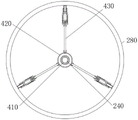
As shown in fig. 1-10, the present invention provides an embodiment: a paint spraying device capable of uniformly spraying the inner and outer surfaces of a mechanical part simultaneously comprises a device body 100, the device body 100 comprises a paint sprayer outer shell 110, the top end of the paint sprayer outer shell 110 is fixedly connected with a paint spraying cavity body 120, the bottom end of the paint spraying cavity body 120 is fixedly connected with a main paint injection pipeline 130, the main paint injection pipeline 130 is inserted in the paint sprayer outer shell 110, the front end of the main paint injection pipeline 130 is inserted with a control valve 140, the bottom end of the main paint injection pipeline 130 is in bearing connection with a first paint injection pipeline 150, the bottom end of the first paint injection pipeline 150 is in sliding connection with a second paint injection pipeline 160, the outer wall of the second paint injection pipeline 160 is in bearing connection with a lifting plate 170, the top end of the lifting plate 170 is fixedly connected with a first output motor 180, the left end of the first output motor 180 is fixedly connected with an output shaft 190, the left end of the output shaft 190 is fixedly connected with a first bevel, the outer wall of the second bevel gear 192 is meshed with the first bevel gear 191, a paint spraying mechanism 200 is arranged below the second paint injection pipeline 160, the paint spraying mechanism 200 comprises a first branch pipeline 210, the left side and the right side of the bottom end of the second paint injection pipeline 160 are connected with the first branch pipeline 210 through four-way pipe threads, one end, away from the second paint injection pipeline 160, of the first branch pipeline 210 is connected with a second branch pipeline 220 through right-angle pipe threads, the inner sides of the two groups of second branch pipelines 220 are connected with outer wall spray nozzles 230 through threads, the bottom end of the second paint injection pipeline 160 is connected with a third branch pipeline 240 through four-way pipe threads, the left side and the right side of the third branch pipeline 240 are connected with branch paint injection pipelines 250 through three-way pipe threads, one ends, away from the third branch pipeline 240, of the two groups of branch paint injection pipelines 250 are connected with inner wall spray nozzles 260 through threads, the outer wall, the reciprocating mechanism 300 is arranged below the lifting plate 170, the reciprocating mechanism 300 comprises a second connecting rod 310, two groups of second connecting rods 310 are connected to the left end of the outer shell 110 of the paint spraying machine in a bearing mode, the outer walls of the second connecting rods 310 are fixedly connected with first gears 320, the two groups of first gears 320 are meshed with each other, second gears 330 are fixedly connected to the outer walls of the two groups of second connecting rods 310, a second output motor 340 is fixedly connected to the left end of the lower second connecting rod 310, a supporting base 350 is fixedly connected to the bottom end of the second output motor 340, the right end of the supporting base 350 is fixedly connected to the outer shell 110 of the paint spraying machine, a third connecting rod 360 is connected to the left end of the outer shell 110 of the paint spraying machine in a bearing mode, a third gear 370 is fixedly connected to the left end of the third connecting rod 360, the outer wall of the third gear 370 is meshed with the second gear, and rack 390 front end meshing in fourth gear 380, third branch pipeline 240 outer wall is provided with supporting mechanism 400, through this mechanism, can carry out comprehensive even spraying paint to spraying 280 internal surface and surface, solved that traditional paint spraying apparatus can't spray paint to the part internal surface when spraying paint to the part surface, cooperate foretell reciprocating mechanism 300 simultaneously, make the device can carry out reciprocating type spraying paint from top to bottom to spraying 280 when can be to the rotatory spraying paint of spraying 280 internal and external surfaces, can be comprehensive to the spraying 280 internal and external surfaces carry out comprehensive even spraying paint promptly.
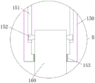
First annotate inside second spout 151 of having seted up of lacquer pipeline 150, and the inside sliding connection of second spout 151 has second slider 152, and second slider 152 keeps away from the one end fixed connection of second spout 151 in second annotates lacquer pipeline 160, through the inside gliding effect of second slider 152 in second spout 151, has promoted the stability of second notes lacquer pipeline 160 when reciprocating.
The bottom end of the first paint injection pipeline 150 is provided with a groove, the inner wall of the groove is fixedly connected with a sealing gasket 153, the sealing gasket 153 is made of rubber, and the sealing performance of the second paint injection pipeline 160 inside the first paint injection pipeline 150 when the second paint injection pipeline moves up and down is guaranteed under the action of the sealing gasket 153.
The inside third spout 271 that has seted up of fixed plate 270, and the inside sliding connection of third spout 271 has two sets of third sliders 272, and the one end that third spout 271 was kept away from to two sets of third sliders 272 all fixedly connected with head rod 273, and the one end that third slider 272 was kept away from to head rod 273 all fixedly connected in notes lacquer pipeline 250, through the inside gliding effect of third slider 272 in third spout 271, the stability of head rod 273 when rotatory has been guaranteed.
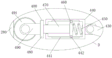
The supporting mechanism 400 comprises a threaded rod 410, the outer wall of the third branched pipe 240 is connected with the threaded rod 410 by a bearing, the outer wall of the threaded rod 410 is sleeved with a sleeve ring 420, the outer wall of the sleeve ring 420 is hinged with three groups of first hinged rods 430, one ends of the first hinged rods 430 far away from the sleeve ring 420 are hinged with sleeves 440, the inner walls of the three groups of sleeves 440 are fixedly connected with springs 450, the other ends of the springs 450 are fixedly connected with first connecting plates 460, one ends of the three groups of first connecting plates 460 far away from the springs 450 are fixedly connected with fourth connecting rods 470, one ends of the fourth connecting rods 470 are fixedly connected with second connecting plates 480, one ends of the three groups of second connecting plates 480 far away from the fourth connecting rods 470 are fixedly connected with two groups of side plates 490, pulleys 491 are connected between the two groups of side plates 490 by rotating shafts, the top end of the fixed plate 270 is hinged with three groups of, through this mechanism, can make the device support anomalous shape for the device can evenly spray paint the anomalous shape part, has promoted the applicable interval of device.
Threaded rod 410 outer wall shape and lantern ring 420 inner wall shape all set up to the screw thread form, and threaded rod 410 outer wall shape and lantern ring 420 inner wall shape match each other, and through threaded rod 410 and lantern ring 420 threaded connection's effect, when threaded rod 410 rotated, can drive lantern ring 420 and reciprocate on the threaded rod 410 surface.
The third sliding grooves 441 are formed in the third set of sleeves 440, the fourth sliding blocks 442 are slidably connected to the third sliding grooves 441, ends of the third set of sliding blocks 442, which are far away from the fourth sliding grooves 441, are fixedly connected to the first connecting plate 460, and the stability of the first connecting plate 460 moving left and right is improved by the sliding action of the fourth sliding blocks 442 in the fourth sliding grooves 441.
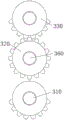
The working principle is as follows: rotating the control valve 140, at this time, the paint inside the main paint spraying cavity 120 can enter the first paint injecting pipeline 150 and the second paint injecting pipeline 160 through the main paint injecting pipeline 130, and then enter the second branch pipeline 220 and the third branch pipeline 240 through the four-way pipe, at this time, the paint inside the third branch pipeline 240 enters the branch paint injecting pipeline 250 through the three-way pipe, at the same time, the paint inside the branch paint injecting pipeline 250 and the second branch pipeline 220 is sprayed out through the outer wall nozzle 230 and the inner wall nozzle 260, the first output motor 180 and the second output motor 340 are started, the output shaft 190 and the first bevel gear 191 can be driven to rotate through the first output motor 180, the second bevel gear 192 can be driven to rotate through the meshing of the first bevel gear 191 and the second bevel gear 192, the second paint injecting pipeline 160 and the first paint injecting pipeline 150 can be driven to rotate through the second bevel gear 192, and the third branch pipeline 240 can be driven to rotate at the same time, the first branch pipe 210, the second branch pipe 220 and the outer wall nozzle 230 rotate periodically, the outer surface and the inner surface of the spray part 280 can be sprayed simultaneously through the rotation of the outer wall nozzle 230 and the inner wall nozzle 260, so that the uniform spraying effect of the device is ensured, the device can simultaneously spray the inner surface and the outer surface of the spray part 280, when the second output motor 340 is started, the second output motor 340 can drive the second connecting rod 310, the first gear 320 and the second gear 330 to rotate, meanwhile, because the two groups of first gears 320 are meshed, the rotating directions of the two groups of first gears 320 are opposite, the two groups of second gears 330 rotate in opposite directions, the third gear 370 can rotate in opposite directions after rotating in the forward direction through the two groups of second gears 330, the third gear 370 and the fourth gear 380 rotate in opposite directions in a reciprocating manner, and the rack 390 can move up and down in a reciprocating manner through the meshing of the fourth gear 380 and the rack 390, thereby driving the two groups of inner wall nozzles 260 and the two groups of outer wall nozzles 230 to rotate and reciprocate up and down;
holding the fixing plate 270, then rotating the threaded rod 410, can drive the lantern ring 420 to move downwards through threaded connection of the threaded rod 410 and the lantern ring 420, thereby drive the first hinge rod 430 to rotate, and the one end of the first hinge rod 430 far away from the lantern ring 420 rotates to the direction of the lantern ring 420, thereby drive the sleeve 440, the fourth connecting rod 470 and the second connecting plate 480 move to the direction of the lantern ring 420, insert it inside the spraying piece 280, reversely rotate the threaded rod 410, can drive the three sets of sleeves 440 to move to the one end far away from the lantern ring 420, and the pulley 491 abuts against the inner wall of the spraying piece 280, so that the first connecting plate 460 extrudes the spring 450, through the elastic action of the spring 450, the pulley 491 can be pushed to abut against the inner wall of the spraying piece 280, thereby support the third branched pipe 240, when the third branched pipe 240 drives the lantern ring 420 to move up and down, through the rolling of the pulley 491, the up-down and down stability of the third branched Friction of the wall, to the end of this operation.
It will be evident to those skilled in the art that the invention is not limited to the details of the foregoing illustrative embodiments, and that the present invention may be embodied in other specific forms without departing from the spirit or essential attributes thereof. The present embodiments are therefore to be considered in all respects as illustrative and not restrictive, the scope of the invention being indicated by the appended claims rather than by the foregoing description, and all changes which come within the meaning and range of equivalency of the claims are therefore intended to be embraced therein. Any reference sign in a claim should not be construed as limiting the claim concerned.
Claims (8)
1. The utility model provides a can be simultaneously to paint spraying apparatus of mechanical part internal and external surface even spraying, includes device main part (100), its characterized in that: the device main body (100) comprises a paint sprayer outer shell (110), a paint spraying cavity main body (120) is fixedly connected to the top end of the paint sprayer outer shell (110), a main paint injection pipeline (130) is fixedly connected to the bottom end of the paint spraying cavity main body (120), the main paint injection pipeline (130) is inserted into the paint sprayer outer shell (110), a control valve (140) is inserted into the front end of the main paint injection pipeline (130), a first paint injection pipeline (150) is connected to a bottom end bearing of the main paint injection pipeline (130), a second paint injection pipeline (160) is slidably connected to the bottom end of the first paint injection pipeline (150), a lifting plate (170) is connected to an outer wall bearing of the second paint injection pipeline (160), a first output motor (180) is fixedly connected to the top end of the lifting plate (170), an output shaft (190) is fixedly connected to the left end of the first output motor (180), and a first bevel gear (191) is fixedly connected to the left end of, the outer wall of the second paint injection pipeline (160) is fixedly connected with a second bevel gear (192), the outer wall of the second bevel gear (192) is meshed with the first bevel gear (191), a paint spraying mechanism (200) is arranged below the second paint injection pipeline (160), the paint spraying mechanism (200) comprises a first branch pipeline (210), the left side and the right side of the bottom end of the second paint injection pipeline (160) are connected with the first branch pipeline (210) through four-way pipe threads, one end, far away from the second paint injection pipeline (160), of the first branch pipeline (210) is connected with a second branch pipeline (220) through right-angle pipe threads, the inner sides of the two groups of second branch pipelines (220) are connected with outer wall spray heads (230) through threads, the bottom end of the second paint injection pipeline (160) is connected with a third branch pipeline (240) through four-way pipe threads, the left side and the right side of the third branch pipeline (240) are connected with branch paint injection pipelines (250, two sets of the third branch pipeline (240) is kept away from by the branch injection paint pipeline (250), one end of the third branch pipeline (240) is connected with an inner wall sprayer (260) through threads, the outer wall of the third branch pipeline (240) is connected with a fixing plate (270) through threads, a spraying part (280) is sleeved outside the third branch pipeline (240), a reciprocating mechanism (300) is arranged below the lifting plate (170), the reciprocating mechanism (300) comprises a second connecting rod (310), the left end of the outer shell (110) of the paint spraying machine is connected with two sets of second connecting rods (310) through bearings, the outer wall of each second connecting rod (310) is fixedly connected with a first gear (320), the two sets of first gears (320) are meshed with each other, the outer walls of the two sets of second connecting rods (310) are fixedly connected with a second gear (330), the left end of the second connecting rod (310) is fixedly connected with a second output motor (340), and the bottom end of the, support base (350) right-hand member fixed connection in paint spraying machine shell body (110), paint spraying machine shell body (110) left end bearing is connected with third connecting rod (360), and third connecting rod (360) left end fixedly connected with third gear (370), third gear (370) outer wall meshes in second gear (330), third connecting rod (360) right-hand member fixedly connected with fourth gear (380), lifter plate (170) bottom fixedly connected with rack (390), and rack (390) front end meshing in fourth gear (380), third minute pipeline (240) outer wall is provided with supporting mechanism (400).
2. The paint spraying apparatus according to claim 1, wherein the inner and outer surfaces of the mechanical part are uniformly coated at the same time, and the paint spraying apparatus comprises: first annotate inside second spout (151) of having seted up of lacquer pipeline (150), and inside sliding connection of second spout (151) has second slider (152), the one end fixed connection of second spout (151) is kept away from in second slider (152) annotates lacquer pipeline (160) in the second.
3. The paint spraying apparatus according to claim 1, wherein the inner and outer surfaces of the mechanical part are uniformly coated at the same time, and the paint spraying apparatus comprises: first notes lacquer pipeline (150) bottom has seted up the recess, and recess inner wall fixedly connected with sealed pad (153), sealed pad (153) material is the rubber material.
4. The paint spraying apparatus according to claim 1, wherein the inner and outer surfaces of the mechanical part are uniformly coated at the same time, and the paint spraying apparatus comprises: first spout (111) have all been seted up to the inner wall of the paint sprayer shell body (110) left and right sides, and first spout (111) inside all sliding connection has first slider (112), two sets of first slider (112) keep away from the one end all fixed connection in lifter plate (170) of first spout (111).
5. The paint spraying apparatus according to claim 1, wherein the inner and outer surfaces of the mechanical part are uniformly coated at the same time, and the paint spraying apparatus comprises: the fixed plate (270) is internally provided with a third sliding groove (271), the third sliding groove (271) is internally and slidably connected with two sets of third sliding blocks (272), the third sliding blocks (272) are both fixedly connected with a first connecting rod (273) at one end far away from the third sliding groove (271), and the first connecting rod (273) is both fixedly connected with the branch injection paint pipeline (250) at one end far away from the third sliding block (272).
6. The paint spraying apparatus according to claim 1, wherein the inner and outer surfaces of the mechanical part are uniformly coated at the same time, and the paint spraying apparatus comprises: the supporting mechanism (400) comprises a threaded rod (410), the outer wall of the third branch pipeline (240) is connected with the threaded rod (410) in a bearing mode, a sleeve ring (420) is sleeved on the outer wall of the threaded rod (410), three groups of first hinged rods (430) are hinged to the outer wall of the sleeve ring (420), sleeves (440) are hinged to one ends, far away from the sleeve ring (420), of the first hinged rods (430), springs (450) are fixedly connected to the inner walls of the three groups of sleeves (440), the other ends of the springs (450) are fixedly connected with a first connecting plate (460), three groups of fourth connecting plates (470) are fixedly connected to one ends, far away from the springs (450), of the first connecting plates (470), of the fourth connecting plates (480), and two groups of side plates (490) are fixedly connected to one ends, far away from the fourth connecting plates (470), of the second connecting plates (480), two sets of be connected with pulley (491) through the pivot between curb plate (490), fixed plate (270) top articulates there are three sets of second articulated rods (492), and three sets of second articulated rod (492) keep away from the one end of fixed plate (270) and all articulate in first articulated rod (430).
7. The paint spraying apparatus according to claim 6, wherein the inner and outer surfaces of the mechanical part are uniformly coated at the same time, and the paint spraying apparatus comprises: the outer wall shape of the threaded rod (410) and the inner wall shape of the sleeve ring (420) are both set to be threaded, and the outer wall shape of the threaded rod (410) and the inner wall shape of the sleeve ring (420) are matched with each other.
8. The paint spraying apparatus according to claim 6, wherein the inner and outer surfaces of the mechanical part are uniformly coated at the same time, and the paint spraying apparatus comprises: the third group of sleeves (440) are all provided with fourth sliding grooves (441) inside, the fourth sliding grooves (441) are all connected with fourth sliding blocks (442) inside in a sliding manner, and the third group of fourth sliding blocks (442) are all fixedly connected to the first connecting plate (460) at the ends far away from the fourth sliding grooves (441).
Priority Applications (1)
| Application Number | Priority Date | Filing Date | Title |
|---|---|---|---|
| CN202011394341.3A CN113000249A (en) | 2020-12-03 | 2020-12-03 | Paint spraying equipment capable of uniformly spraying inner and outer surfaces of mechanical part simultaneously |
Applications Claiming Priority (1)
| Application Number | Priority Date | Filing Date | Title |
|---|---|---|---|
| CN202011394341.3A CN113000249A (en) | 2020-12-03 | 2020-12-03 | Paint spraying equipment capable of uniformly spraying inner and outer surfaces of mechanical part simultaneously |
Publications (1)
| Publication Number | Publication Date |
|---|---|
| CN113000249A true CN113000249A (en) | 2021-06-22 |
Family
ID=76383590
Family Applications (1)
| Application Number | Title | Priority Date | Filing Date |
|---|---|---|---|
| CN202011394341.3A Withdrawn CN113000249A (en) | 2020-12-03 | 2020-12-03 | Paint spraying equipment capable of uniformly spraying inner and outer surfaces of mechanical part simultaneously |
Country Status (1)
| Country | Link |
|---|---|
| CN (1) | CN113000249A (en) |
Cited By (5)
| Publication number | Priority date | Publication date | Assignee | Title |
|---|---|---|---|---|
| CN113441317A (en) * | 2021-06-29 | 2021-09-28 | 电建阀门丽水有限公司 | Automatic positioning paint spraying and drying device for valve and using method |
| CN114100899A (en) * | 2021-11-09 | 2022-03-01 | 广德衡峰新型建材有限公司 | Flush coater is used in processing of waterborne fluorocarbon application panel |
| CN114210489A (en) * | 2021-12-17 | 2022-03-22 | 郜昕 | Vertical equal-diameter curved paint spraying equipment on bridge frame |
| CN114769035A (en) * | 2022-06-22 | 2022-07-22 | 诸城市圣阳机械有限公司 | Automatic paint spraying device |
| CN115463770A (en) * | 2022-09-26 | 2022-12-13 | 青岛天能重工股份有限公司 | Paint spraying equipment and process for inner wall and outer wall of wind power generation tower |
-
2020
- 2020-12-03 CN CN202011394341.3A patent/CN113000249A/en not_active Withdrawn
Cited By (6)
| Publication number | Priority date | Publication date | Assignee | Title |
|---|---|---|---|---|
| CN113441317A (en) * | 2021-06-29 | 2021-09-28 | 电建阀门丽水有限公司 | Automatic positioning paint spraying and drying device for valve and using method |
| CN114100899A (en) * | 2021-11-09 | 2022-03-01 | 广德衡峰新型建材有限公司 | Flush coater is used in processing of waterborne fluorocarbon application panel |
| CN114210489A (en) * | 2021-12-17 | 2022-03-22 | 郜昕 | Vertical equal-diameter curved paint spraying equipment on bridge frame |
| CN114769035A (en) * | 2022-06-22 | 2022-07-22 | 诸城市圣阳机械有限公司 | Automatic paint spraying device |
| CN114769035B (en) * | 2022-06-22 | 2022-09-02 | 诸城市圣阳机械有限公司 | Automatic paint spraying device |
| CN115463770A (en) * | 2022-09-26 | 2022-12-13 | 青岛天能重工股份有限公司 | Paint spraying equipment and process for inner wall and outer wall of wind power generation tower |
Similar Documents
| Publication | Publication Date | Title |
|---|---|---|
| CN113000249A (en) | Paint spraying equipment capable of uniformly spraying inner and outer surfaces of mechanical part simultaneously | |
| CN108787218B (en) | Pipeline spraying device | |
| CN110538742B (en) | Pipeline sprayer capable of spraying uniformly | |
| CN105214875A (en) | A kind of tubular tank surface spraying equipment | |
| CN114042575A (en) | Environment-friendly spraying device and using method thereof | |
| CN112024192B (en) | A spraying mechanism for new material plastic products production | |
| CN117160754B (en) | Rust-proof oil coating equipment | |
| CN219463869U (en) | Roller coating device for metal barrel coating | |
| CN107214022B (en) | A kind of cosmetic cover body spraying mould | |
| CN212468614U (en) | Tank spraying device | |
| CN112643445B (en) | Pipe body port burr removing device | |
| CN112547343B (en) | Nanometer coating spraying equipment | |
| CN207709283U (en) | A kind of surface coating device of column steel billet | |
| CN114345581A (en) | Paint spraying device for large steel structure | |
| CN114472058A (en) | Lithium battery pole piece coating uniformity improving equipment | |
| CN220559572U (en) | Plastic spraying equipment capable of automatically and uniformly spraying | |
| CN220461067U (en) | Steel construction processing spraying device | |
| CN215964295U (en) | Automatic electrostatic spraying equipment of work piece | |
| CN221063244U (en) | Nano coating uniform speed spraying machine | |
| CN216500184U (en) | Spraying device with automatic circulation stroke | |
| CN111701761B (en) | Pipeline inner wall spraying device | |
| CN215389157U (en) | A supplementary feed mechanism for cosmetics production and processing equipment | |
| CN218690796U (en) | Stainless steel strip surface coating machine for decoration | |
| CN221658759U (en) | Gantry machining center sliding block lubricating device | |
| CN219409950U (en) | Electrophoresis line powder spraying device with interval adjusting function |
Legal Events
| Date | Code | Title | Description |
|---|---|---|---|
| PB01 | Publication | ||
| PB01 | Publication | ||
| SE01 | Entry into force of request for substantive examination | ||
| SE01 | Entry into force of request for substantive examination | ||
| WW01 | Invention patent application withdrawn after publication |
Application publication date: 20210622 |
|
| WW01 | Invention patent application withdrawn after publication |