CN112984872A - High-efficiency water-saving countercurrent water circulation heat exchange type condenser - Google Patents
High-efficiency water-saving countercurrent water circulation heat exchange type condenser Download PDFInfo
- Publication number
- CN112984872A CN112984872A CN202110236008.8A CN202110236008A CN112984872A CN 112984872 A CN112984872 A CN 112984872A CN 202110236008 A CN202110236008 A CN 202110236008A CN 112984872 A CN112984872 A CN 112984872A
- Authority
- CN
- China
- Prior art keywords
- pipe
- water
- water collecting
- heat exchange
- condenser
- Prior art date
- Legal status (The legal status is an assumption and is not a legal conclusion. Google has not performed a legal analysis and makes no representation as to the accuracy of the status listed.)
- Granted
Links
Images


Classifications
-
- F—MECHANICAL ENGINEERING; LIGHTING; HEATING; WEAPONS; BLASTING
- F25—REFRIGERATION OR COOLING; COMBINED HEATING AND REFRIGERATION SYSTEMS; HEAT PUMP SYSTEMS; MANUFACTURE OR STORAGE OF ICE; LIQUEFACTION SOLIDIFICATION OF GASES
- F25B—REFRIGERATION MACHINES, PLANTS OR SYSTEMS; COMBINED HEATING AND REFRIGERATION SYSTEMS; HEAT PUMP SYSTEMS
- F25B39/00—Evaporators; Condensers
- F25B39/04—Condensers
-
- F—MECHANICAL ENGINEERING; LIGHTING; HEATING; WEAPONS; BLASTING
- F25—REFRIGERATION OR COOLING; COMBINED HEATING AND REFRIGERATION SYSTEMS; HEAT PUMP SYSTEMS; MANUFACTURE OR STORAGE OF ICE; LIQUEFACTION SOLIDIFICATION OF GASES
- F25B—REFRIGERATION MACHINES, PLANTS OR SYSTEMS; COMBINED HEATING AND REFRIGERATION SYSTEMS; HEAT PUMP SYSTEMS
- F25B2339/00—Details of evaporators; Details of condensers
- F25B2339/04—Details of condensers
- F25B2339/041—Details of condensers of evaporative condensers
Landscapes
- Engineering & Computer Science (AREA)
- Physics & Mathematics (AREA)
- Mechanical Engineering (AREA)
- Thermal Sciences (AREA)
- General Engineering & Computer Science (AREA)
- Heat-Exchange Devices With Radiators And Conduit Assemblies (AREA)
Abstract
The invention relates to the technical field of condensing mechanical structures, in particular to a high-efficiency water-saving countercurrent water circulation heat exchange type condenser which comprises a condenser shell, a heat exchanger, a liquid inlet pipe, a liquid outlet pipe, a water distribution pipe, an exhaust fan, an air inlet grille, a water collecting tank, a water collector and a flow guide system.
Description
Technical Field
The invention relates to the technical field of condensing mechanical structures, in particular to a high-efficiency water-saving countercurrent water circulation heat exchange type condenser.
Background
In modern society, the application of refrigeration technology has been involved in various sectors of national economy and in people's daily lives. However, water resources in China are deficient, and particularly, under the situation that electric power resources are increasingly tense in recent years, higher requirements are made on energy conservation of a refrigeration system. Common condensers are generally classified into a water-cooled type, an air-cooled type and an evaporative type according to a cooling medium and a cooling method. The evaporative condenser takes spray water as a cooling medium, the water forms a water film outside the coil pipe, the water exchanges heat with process fluid in the coil pipe, the temperature rises after heat absorption, part of cooling water is gasified to form water vapor, a large amount of heat is taken away by water evaporation and is sucked by a fan and discharged into the atmosphere, redundant water on the heat exchanger can be collected into a water collecting tank, then the water vapor is recycled through a water pump and a return pipe, however, when the actual condenser works, the water on the surface of the heat exchanger is evaporated to be changed into the water vapor to be discharged, a large amount of water in a small water droplet atomizing state is also arranged in the water vapor, and the small water droplets directly fly away along with the water vapor, so that the water loss in the water collecting tank is very fast, frequent water.
Patent document No. CN201510596128.3 discloses a water circulation evaporation heat exchange cooling type condenser, which comprises a condenser casing, a heat exchanger is arranged in the middle of the condenser casing, a liquid inlet pipe is arranged on the side surface of the upper end of the heat exchanger, a liquid outlet pipe is arranged on the side surface of the lower end of the heat exchanger, a water distribution pipe is arranged on the upper end of the heat exchanger in the condenser casing, a plurality of nozzles are uniformly arranged on the lower side of the water distribution pipe, an exhaust fan is arranged on the top of the condenser casing, an air inlet grid is arranged on the side surface of the lower end of the condenser casing, a water collection tank is arranged at the bottom of the condenser casing, a return pipe is arranged on the side surface of the condenser casing, the lower end of the return.
However, the water collecting effect of the water collector disclosed by the above technical scheme is not ideal, and the moisture and the liquid drops generated at the cooling pipe are discharged upwards along with the action of the exhaust fan, which brings great difficulty to the collection of the liquid drops.
Disclosure of Invention
Aiming at the problems, the invention provides a high-efficiency water-saving countercurrent water circulation heat exchange type condenser, which is characterized in that a water collecting unit with a water collecting function is arranged on a water collector, a large amount of water drops are collected and concentrated by the water collecting unit, then the water collecting unit is extruded to release the collected water drops at one time, and a flow guide system is arranged on a heat exchanger in a matching manner to separate and guide water vapor and liquid drops generated on a cooling pipe to the water collecting unit for condensation and collection, so that liquid is retained as much as possible, and the technical problem that the water collecting and water collecting effects of the existing water collector are not ideal is solved.
In order to achieve the purpose, the invention provides the following technical scheme:
the utility model provides a high-efficient water conservation is hydrologic cycle heat transfer formula condenser against current, includes the condenser casing, still includes:
the heat exchanger is positioned in the middle of the condenser shell in the height direction;
the liquid inlet pipe is arranged in the condenser shell and is positioned above the upper end surface of the heat exchanger;
the liquid outlet pipe is arranged in the condenser shell and is positioned below the lower end surface of the heat exchanger, and a heat exchange pipe is communicated between the liquid outlet pipe and the liquid inlet pipe;
the water distribution pipe is arranged in the condenser shell, a plurality of nozzles are uniformly distributed on the lower side of the water distribution pipe, and the nozzles spray cooling liquid to the heat exchange pipe;
the exhaust fan is arranged at an opening at the top of the condenser shell;
the air inlet grille is arranged on the side wall of the condenser shell and is positioned below the liquid outlet pipe, and a heat exchange filler is arranged at the air inlet grille;
the water collecting tank is arranged at the bottom of the condenser shell, the heat exchange filler body covers an opening of the water collecting tank, and the water collecting tank is communicated with the water distribution pipe through a circulating reflux system;
the water collector is arranged between the water distribution pipe and the exhaust fan and comprises a plurality of corrugated plates arranged in a wave shape and connecting columns integrally connected with the corrugated plates, water collecting units are arranged at wave troughs of the corrugated plates, arc-shaped water collecting plates are arranged at wave crests of the corrugated plates, and the water collecting units are used for collecting liquid drops retained by the water collecting plates; and
the flow guide system penetrates through the heat exchanger and comprises a flow guide unit arranged in a hollow mode and a driving unit driving the flow guide unit to rotate, the flow guide unit is communicated with the water receiving unit, and the driving unit synchronously drives the water receiving unit to operate.
As an improvement, the heat exchanger includes a plurality of vertical parallel distribution's heat transfer board, is equipped with the cooling clearance between the heat transfer board, be equipped with the fluid passage of a plurality of parallels in the heat transfer board, all fluid passage connect gradually and form square wave form passageway, the feed liquor pipe be located the import department of square wave form passageway on every heat transfer board, the drain pipe is located the exit of square wave form passageway on every heat transfer board, the cooling clearance in be equipped with the heat transfer filler plate, the heat transfer filler plate is formed by two trapezoidal ripple filler plate coincide, is equipped with a plurality of support columns on the top surface on the trapezoidal ripple filler plate.
As an improvement, the heat exchange tubes are arranged in a snake shape, penetrate through the heat exchanger and are arranged along the axial direction of the liquid inlet tube in a staggered mode.
As an improvement, a pre-cooling system is arranged above the liquid inlet pipe, and comprises:
the pre-cooling pipe is arranged in a U shape and is communicated with the liquid inlet pipe; and
and the plurality of radiating fins are arranged on the precooling pipe at equal intervals along the axial direction of the precooling pipe.
As an improvement, the radiating fins are arranged in a fan blade shape and are rotatably sleeved on the pre-cooling pipe.
As an improvement, the circulation reflux system comprises:
the return pipe is arranged to communicate the water collecting tank and the water distribution pipe;
the reflux pump is arranged on the reflux pipe and pumps the cooling liquid in the water collecting tank to the water distribution pipe; and
and the electronic water scale remover is arranged on the return pipe and is used for filtering the cooling liquid flowing in the return pipe.
As an improvement, the water receiving unit comprises:
the water collecting pipe is integrally connected with the corrugated plate along the length direction of the corrugated plate, the water collecting pipe is arranged in a round pipe shape, and a plurality of through holes are arranged on the side wall of the water collecting pipe, which is not connected with the corrugated plate, in a penetrating manner;
the sponge column is inserted into the water collecting pipe and absorbs water vapor through the through hole;
the squeezing heads are symmetrically arranged on two axial sides of the water collecting pipe, push and squeeze the sponge columns towards the water collecting pipe, are arranged in a hollow mode and are communicated with the flow guide unit through hoses;
the fixed seat is arranged corresponding to the extrusion head and is positioned on one side of the extrusion head away from the water collecting pipe, and the extrusion head is slidably mounted on the fixed seat;
the return spring is arranged between the extrusion head and the fixed seat in an abutting mode; and
and the transmission connecting group is in transmission connection with the driving unit, and the driving unit drives the extrusion head to slide along the fixed seat.
As an improvement, the water receiving unit further comprises:
the water collecting plate is rotatably arranged on the corrugated plate and is arranged in an arc shape, and a spring plate for driving the water collecting plate to elastically reset is arranged at the position of an included angle between the water collecting plate and the corrugated plate in a propping manner; and
the plug, the plug install in on the extrusion head, this plug is along with extrusion head synchronous motion, and this plug inserts the water-collecting plate with in the contained angle of buckled plate, the drive the water-collecting plate is opened.
As an improvement, the flow guide unit comprises:
the guide pipe is arranged in a hollow manner, is rotatably arranged on the condenser shell and is communicated with the water receiving unit through a hose, and an air inlet is formed in the side wall of the guide pipe;
the cover plate is arranged in an arc shape and is rotatably arranged on the air inlet;
the rotary sealing joints are symmetrically arranged on two axial sides of the guide pipe, and the rotary sealing joints are arranged between the guide pipe and the hose.
As an improvement, the drive unit includes:
the driven gear is sleeved on any one of the corresponding guide pipes;
the driving motor is arranged on the condenser shell, and a driving gear correspondingly matched with the driven gear is arranged on the driving motor; and
and the belt transmission set is in transmission connection with the adjacent guide pipes and drives the guide pipes to rotate synchronously.
The invention has the beneficial effects that:
(1) according to the invention, the water collecting unit with the water collecting function is arranged on the water collector, a large amount of water drops are collected and concentrated by the water collecting unit, then the water collecting unit is extruded, so that the collected water drops are released at one time, and the guide system is arranged on the heat exchanger in a matching manner, so that water vapor and liquid drops generated on the cooling pipe are separated and guided to the water collecting unit for condensation and collection, and liquid is retained as much as possible, thereby solving the technical problem that the water collecting and water collecting effects of the existing water collector are not ideal;
(2) the liquid drops collected by the water collecting plate are absorbed in a concentrated manner by the sponge columns in the water collecting unit, and after the absorbed liquid drops are accumulated to a certain amount, the sponge columns are extruded to release the liquid drops absorbed by the sponge columns at one time;
(3) according to the invention, the sponge column is blocked by opening the water collecting plate, so that the interference of water flow generated by extruding the sponge column to the air flow of the exhaust fan is reduced, the water flow can flow downwards more smoothly, and the retention of cooling liquid is facilitated;
(4) according to the invention, through the rotation of the flow guide pipe, the air inlet on the flow guide pipe is opened when the air inlet is positioned below the flow guide pipe, water vapor moves upwards, enters the flow guide pipe, is transferred to the sponge column through the flow guide pipe to be adsorbed, and liquid entering the flow guide pipe still moves downwards to act on cooling work;
(5) the invention uses the wind power of the exhaust fan to cool the cooling liquid flowing in the pre-cooling pipe in one step, thereby improving the cooling efficiency of the water circulation countercurrent heat exchange type condenser as much as possible, reducing the water utilization rate in single condensation work as much as possible and simultaneously retaining the cooling liquid as much as possible;
(6) the radiating fins for radiating on the pre-cooling pipe are rotationally arranged, and are driven by the wind power of the exhaust fan to rotate, so that the rotating radiating fins can more effectively carry out heat convection, and meanwhile, the radiating of all parts of the radiating fins is more even, and the coolant in the pre-cooling pipe is uniformly pre-cooled;
(7) the heat exchange tubes are arranged in a staggered mode, and the space between the heat exchange tubes is enlarged, so that generated water vapor can be smoothly discharged upwards in the condensation process of the heat exchange tubes and cannot be blocked by the heat exchange tubes on the upper portion.
In conclusion, the invention has the advantages of high automation degree, high cyclic utilization rate, high cooling efficiency, high liquid stagnation efficiency and the like, and is particularly suitable for the technical field of condensing mechanical structures.
Drawings
FIG. 1 is a schematic perspective view of the present invention;
FIG. 2 is a schematic view of the internal structure of the present invention;
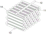
FIG. 3 is a schematic perspective view of a heat exchange tube according to the present invention;
FIG. 4 is a schematic diagram of the structure of the water distribution pipe according to the present invention;
FIG. 5 is a schematic view of a front view structure of the water collector of the present invention;
FIG. 6 is a schematic perspective view of a water collecting unit according to the present invention;
FIG. 7 is an enlarged view of the structure at A in FIG. 6;
FIG. 8 is a schematic sectional view of a water collecting unit according to the present invention;
FIG. 9 is a schematic perspective view of a water collecting unit according to the present invention;
FIG. 10 is a perspective view of the transmission coupling set of the present invention;
FIG. 11 is a schematic cross-sectional view of an extrusion head according to the present invention;
FIG. 12 is a schematic perspective view of a diversion system of the present invention;
FIG. 13 is a schematic perspective view of a driving unit according to the present invention;
fig. 14 is a schematic perspective view of the flow guide tube of the present invention.
Detailed Description
The technical solutions in the embodiments of the present invention will be clearly and completely described below with reference to the drawings in the embodiments of the present invention, and it is obvious that the described embodiments are only a part of the embodiments of the present invention, and not all of the embodiments. All other embodiments, which can be derived by a person skilled in the art from the embodiments given herein without making any creative effort, shall fall within the protection scope of the present invention.
In the description of the present invention, it is to be understood that the terms "center", "longitudinal", "lateral", "length", "width", "thickness", "upper", "lower", "front", "rear", "left", "right", "vertical", "horizontal", "top", "bottom", "inner", "outer", "clockwise", "counterclockwise", and the like, indicate orientations and positional relationships based on those shown in the drawings, and are used only for convenience of description and simplicity of description, and do not indicate or imply that the equipment or element being referred to must have a particular orientation, be constructed and operated in a particular orientation, and thus, should not be considered as limiting the present invention.
Furthermore, the terms "first", "second" and "first" are used for descriptive purposes only and are not to be construed as indicating or implying relative importance or implicitly indicating the number of technical features indicated. Thus, a feature defined as "first" or "second" may explicitly or implicitly include one or more of that feature. In the description of the present invention, "a plurality" means two or more unless specifically defined otherwise.
Example (b):
as shown in fig. 1 to 14, a high-efficiency water-saving countercurrent water circulation heat exchange type condenser includes a condenser shell 1, and further includes:
the heat exchanger 11 is positioned in the middle of the condenser shell 1 in the height direction;
a liquid inlet pipe 12, wherein the liquid inlet pipe 12 is arranged in the condenser shell 1, and the liquid inlet pipe 12 is positioned above the upper end surface of the heat exchanger 11;
the liquid outlet pipe 13 is arranged in the condenser shell 1, the liquid outlet pipe 13 is positioned below the lower end surface of the heat exchanger 11, and a heat exchange pipe 14 is communicated between the liquid outlet pipe 13 and the liquid inlet pipe 12;
the water distribution pipe 15 is arranged in the condenser shell 1, a plurality of nozzles 151 are uniformly distributed on the lower side of the water distribution pipe 15, and the nozzles 151 spray cooling liquid to the heat exchange pipe 14;
the exhaust fan 16 is arranged at the opening at the top of the condenser shell 1;
the air inlet grille 17 is arranged on the side wall of the condenser shell 1, the air inlet grille 17 is positioned below the liquid outlet pipe 13, and a heat exchange filler 171 is arranged at the air inlet grille 17;
the water collecting tank 18 is arranged at the bottom of the condenser shell 1, the heat exchange filler body 171 is arranged to cover the opening of the water collecting tank 18, and the water collecting tank 18 is communicated with the water distribution pipe 15 through a circulation reflux system 19;
the water collecting device 2 is arranged between the water distribution pipe 15 and the exhaust fan 16, the water collecting device 2 comprises a plurality of corrugated plates 21 arranged in a wave shape and connecting columns 22 integrally connected with the corrugated plates 21, water collecting units 23 are arranged at wave troughs of the corrugated plates 21, water collecting plates 24 arranged in an arc shape are arranged at wave crests of the corrugated plates 21, and the water collecting units 23 are used for collecting liquid drops retained by the water collecting plates 24; and
the diversion system 4, the diversion system 4 wears to locate on the heat exchanger 11, and this diversion system 4 includes the guide unit 41 of hollow setting and drives the drive unit 42 of this guide unit 41 rotatory setting, guide unit 41 with receive the water unit 23 intercommunication setting, drive unit 42 synchronous drive receive the water unit 23 operation.
Wherein, the heat exchange filler 171 is disposed in a honeycomb shape.
Further, heat exchanger 11 includes a plurality of vertical parallel distribution's heat transfer board, is equipped with the cooling clearance between the heat transfer board, be equipped with the fluid passage of a plurality of parallels in the heat transfer board, all fluid passage connect gradually and form square wave form passageway, feed liquor pipe 12 be located the import department of the square wave form passageway on every heat transfer board, drain pipe 13 is located the exit of the square wave form passageway on every heat transfer board, the cooling clearance in be equipped with the heat transfer filler plate, the heat transfer filler plate is formed by the coincide of two trapezoidal ripple filler plates, is equipped with a plurality of support columns on the top surface on the trapezoidal ripple filler plate.
It should be noted that, the exhaust fan is turned on, the water pump on the return pipe is turned on, the cooling water in the water distribution pipe is sprayed into the cooling gap in the heat exchanger from the nozzle, the cooling water flows down along the surfaces of the heat exchange filler plate and the heat exchange plate to form a water film, the outside air is fed from the air inlet grid, the airflow passes through the heat exchange filler body, the heat exchanger, the water collector and the radiating fins and is discharged from the top, the high-temperature process fluid firstly enters the pre-cooling pipe 31 for pre-cooling, the temperature of the pre-cooled process fluid is lower than 70 ℃, so as to avoid the scaling points of the water, slow down the scaling of the outer wall of the heat exchange plate and the pipe wall of the fluid passage, the process fluid pre-cooled by the pre-cooling pipe enters the liquid inlet pipe 12 and then respectively enters the square wave passage in each heat exchange plate, the process fluid transfers the heat to the water film, the process fluid is discharged from the liquid outlet pipe after being cooled, the circulating water which is not evaporated and has higher temperature in the cooling gap flows onto the heat exchange filler, the air entering at the air inlet grid exchanges heat with the circulating water in the heat exchange filler to take away the heat, the temperature of the circulating water finally flowing into the water collecting tank is close to the temperature of the cooling water in the water distributing pipe, the water in the water collecting tank enters the water distributing pipe for recycling, the heat exchange between the circulating water and the heat exchanger is improved, and when the liquid level in the water collecting tank is lower than a certain value, the float valve at the water supplementing port is automatically opened for supplementation; the heat exchanger is composed of the plurality of heat exchange plates, the surface area of the square-wave-shaped channel in the heat exchange plates with the same volume is larger than that of the coil pipe, the cooling efficiency is higher than that of the coil pipe, the structure is compact, the size is small, and the cleaning is more convenient.
The structures of the heat exchanger 11 and the heat exchange filler 171 are the same as those of the heat exchanger and the heat exchange filler described in the reference in the background art.
In a preferred embodiment, the heat exchange tubes 14 are arranged in a serpentine shape, the heat exchange tubes 14 are arranged through the heat exchanger 11, and the heat exchange tubes 14 are arranged in a staggered manner along the axial direction of the liquid inlet tube 12.
It should be noted that, by arranging the heat exchange tubes 14 in a staggered manner, the distance between the heat exchange tubes 14 is increased, so that the generated water vapor can be smoothly discharged upwards in the process of condensing the heat exchange tubes 14, and cannot be blocked by the heat exchange tubes 14 existing at the upper part.
As a preferred embodiment, a pre-cooling system 3 is arranged above the liquid inlet pipe 12, and the pre-cooling system 3 comprises:
a pre-cooling pipe 31, wherein the pre-cooling pipe 31 is arranged in a U shape, and the pre-cooling pipe 31 is communicated with the liquid inlet pipe 12; and
the heat radiating fins 32 and a plurality of the heat radiating fins 32 are all arranged on the precooling pipe 31 at equal intervals along the axial direction of the precooling pipe 31.
Further, the heat dissipating fins 32 are disposed in a fan shape, and the heat dissipating fins 32 are rotatably sleeved on the pre-cooling pipe 31.
It should be noted that, by rotationally arranging the heat dissipating fins 32 for dissipating heat on the pre-cooling pipe 31, the heat dissipating fins 32 are rotated under the driving of the wind power of the exhaust fan, so that the heat dissipating fins 32 that rotate can more effectively perform heat convection, and meanwhile, the heat dissipation of each part of the heat dissipating fins 32 can be more even, so as to perform uniform pre-cooling on the coolant in the pre-cooling pipe 31.
As a preferred embodiment, the recirculation loop system 19 comprises:
the return pipe 191 is arranged to communicate the water collecting tank 18 and the water distribution pipe 15;
a reflux pump 192, the reflux pump 192 is disposed on the reflux pipe 191, and the reflux pump 192 pumps the cooling liquid in the water collecting tank 18 to the water distributing pipe 15; and
an electronic water descaler 193, the electronic water descaler 193 being disposed on the return pipe 191, the electronic water descaler 193 filtering the cooling liquid flowing in the return pipe 191.
As a preferred embodiment, the water receiving unit 23 includes:
the water collecting pipe 231 is integrally connected with the corrugated plate 21 along the length direction of the corrugated plate 21, the water collecting pipe 231 is arranged in a circular tube shape, and a plurality of through holes 232 are arranged on the side wall of the water collecting pipe 231, which is not connected with the corrugated plate 21, in a penetrating manner;
the sponge column 233 is inserted into the water collecting pipe 231, and the sponge column 233 absorbs water vapor through the through hole 232;
the extrusion heads 234 are symmetrically arranged at two axial sides of the water collecting pipe 231, the extrusion heads 234 push and extrude the sponge column 233 towards the water collecting pipe 231, and the extrusion heads 234 are arranged in a hollow manner and are communicated with the flow guide unit 41 through hoses;
the fixed seat 235 is arranged corresponding to the extrusion head 234 and is positioned on one side of the extrusion head 234 away from the water collecting pipe 231, and the extrusion head 234 is slidably mounted on the fixed seat 235;
a return spring 236, wherein the return spring 236 is disposed between the pressing head 234 and the fixing seat 235 in an abutting manner; and
and the transmission connection group 237 is in transmission connection with the driving unit 42, and the driving unit 42 drives the extrusion head 234 to slide along the fixed seat 235.
Wherein, transmission connection group 237 includes rack 2371, gear 2372, bevel gear pair 2373 and belt transmission pair 2374, rack 2371 with extrusion head 234 body coupling sets up, gear 2372 set up in the below of rack 2371, this gear 2372 corresponds the cooperation with rack 2371, and drive unit 42 is connected in the transmission of belt transmission pair 2374, through the switching-over of bevel gear pair 2374 for gear 2372 rotates.
Further, the water receiving unit 23 further includes:
the water collecting plate 238 is rotatably installed on the corrugated plate 21, the water collecting plate 238 is arranged in an arc shape, and a spring plate for driving the water collecting plate 238 to elastically reset is installed at an included angle position between the water collecting plate 238 and the corrugated plate 21 in an abutting mode; and
the plug 239 is mounted on the extrusion head 234, the plug 239 moves synchronously with the extrusion head 234, and the plug 239 is inserted into an included angle between the water collecting plate 238 and the corrugated plate 21 to drive the water collecting plate 238 to open.
It should be noted that, in the channel formed by the corrugated plate 21, the mixture of the water vapor and the liquid drops enters the channel formed by the corrugated plate 21, the water vapor and the liquid drops flow upward along the side wall of the corrugated plate 21, in this process, the liquid drops collide with the water collecting plate 24, are retained by the water collecting plate 24, and are continuously concentrated toward the water collecting pipe 231, and after being collected by the sponge column 233, the liquid absorbed in the sponge column 233 is released at one time by pressing the sponge column 233, so that the liquid flows downward in a concentrated manner, and in the process that the liquid flows downward in a concentrated manner by being pressed, the water collecting plate 238 is opened to block the sponge column 233, thereby avoiding the interference of the air flow on the water flow.
As a preferred embodiment, the flow guide unit 41 includes:
the guide pipe 411 is arranged in a hollow manner, the guide pipe 411 is rotatably mounted on the condenser shell 1, the guide pipe 411 is communicated with the water receiving unit 23 through a hose, and the side wall of the guide pipe 411 is provided with an air inlet 412;
the cover plate 413 is arranged in an arc shape, and the cover plate 413 is rotatably arranged on the air inlet 412;
and the rotary sealing joints 414 are symmetrically arranged at two axial sides of the flow guide pipe 411, and the rotary sealing joints 414 are arranged between the flow guide pipe 411 and the hose.
Further, the driving unit 42 includes:
the driven gear 421 is sleeved on any corresponding flow guide pipe 411;
the driving motor 422 is installed on the condenser shell 1, and a driving gear 423 correspondingly matched with the driven gear 421 is arranged on the driving motor 422; and
and the belt transmission group 424 is used for connecting the adjacent guide pipes 411 in a transmission manner, so that the guide pipes 411 are driven to rotate synchronously.
It should be noted that, through the rotation of the draft tube 411, the air inlet 412 on the draft tube 411 is opened when being located below the draft tube 411, the water vapor moves upward, enters the draft tube 411, is transferred to the sponge column 233 through the draft tube 411 to be adsorbed, and the liquid entering the draft tube 411 still moves downward to act on the cooling work.
The above description is only for the purpose of illustrating the preferred embodiments of the present invention and is not to be construed as limiting the invention, and any modifications, equivalents and improvements made within the spirit and principle of the present invention are intended to be included within the scope of the present invention.
Claims (10)
1. The utility model provides a high-efficient water conservation is hydrologic cycle heat transfer formula condenser against current, includes condenser casing (1), its characterized in that still includes:
the heat exchanger (11), the heat exchanger (11) is located in the middle of the condenser shell (1) in the height direction;
the liquid inlet pipe (12) is arranged in the condenser shell (1), and the liquid inlet pipe (12) is positioned above the upper end face of the heat exchanger (11);
the liquid outlet pipe (13) is arranged in the condenser shell (1), the liquid outlet pipe (13) is positioned below the lower end face of the heat exchanger (11), and a heat exchange pipe (14) is communicated between the liquid outlet pipe (13) and the liquid inlet pipe (12);
the water distribution pipe (15) is arranged in the condenser shell (1), a plurality of nozzles (151) are uniformly distributed on the lower side of the water distribution pipe (15), and the nozzles (151) spray cooling liquid to the heat exchange pipe (14);
the exhaust fan (16), the exhaust fan (16) is arranged at the opening at the top of the condenser shell (1);
the air inlet grille (17) is arranged on the side wall of the condenser shell (1), the air inlet grille (17) is positioned below the liquid outlet pipe (13), and a heat exchange filler body (171) is arranged at the air inlet grille (17);
the water collecting tank (18) is arranged at the bottom of the condenser shell (1), the heat exchange filler body (171) is arranged to cover an opening of the water collecting tank (18), and the water collecting tank (18) is communicated with the water distribution pipe (15) through a circulation reflux system (19);
the water collecting device (2) is arranged between the water distribution pipe (15) and the exhaust fan (16), the water collecting device (2) comprises a plurality of corrugated plates (21) which are arranged in a wave shape and connecting columns (22) which are connected with the corrugated plates (21) into a whole, water collecting units (23) are arranged at wave troughs of the corrugated plates (21), water collecting plates (24) which are arranged in an arc shape are arranged at wave crests of the corrugated plates (21), and the water collecting units (23) are used for collecting liquid drops retained by the water collecting plates (24); and
the flow guide system (4) penetrates through the heat exchanger (11), the flow guide system (4) comprises a flow guide unit (41) arranged in a hollow mode and a driving unit (42) driving the flow guide unit (41) to rotate, the flow guide unit (41) is communicated with the water receiving unit (23), and the driving unit (42) synchronously drives the water receiving unit (23) to run.
2. The condenser of claim 1, wherein the heat exchanger (11) comprises a plurality of heat exchange plates vertically distributed in parallel, a cooling gap is provided between the heat exchange plates, a plurality of parallel fluid channels are provided in the heat exchange plates, all the fluid channels are connected in sequence to form a square wave channel, the fluid inlet pipe (12) is located at an inlet of the square wave channel on each heat exchange plate, the fluid outlet pipe (13) is located at an outlet of the square wave channel on each heat exchange plate, a heat exchange filler plate is provided in the cooling gap, the heat exchange filler plate is formed by overlapping two trapezoidal corrugated filler plates, and a plurality of support columns are provided on a top surface of the trapezoidal corrugated filler plate.
3. A high efficiency water saving counter current water circulating heat exchange type condenser according to claim 1 wherein the heat exchange tubes (14) are arranged in a serpentine shape, the heat exchange tubes (14) are arranged through the heat exchanger (11), and the heat exchange tubes (14) are arranged in a staggered arrangement along the axial direction of the liquid inlet tube (12).
4. An efficient water-saving counter-flow water-circulating heat-exchange condenser according to claim 1, characterized in that a pre-cooling system (3) is arranged above the liquid inlet pipe (12), and the pre-cooling system (3) comprises:
the pre-cooling pipe (31), the pre-cooling pipe (31) is arranged in a U shape, and the pre-cooling pipe (31) is communicated with the liquid inlet pipe (12); and
the cooling fins (32) are arranged on the precooling pipe (31) at equal intervals along the axial direction of the precooling pipe (31).
5. The condenser of claim 4, wherein the heat dissipating fins (32) are disposed in a fan shape, and the heat dissipating fins (32) are rotatably sleeved on the pre-cooling pipe (31).
6. A high efficiency water saving counter current water circulating heat exchange condenser as claimed in claim 1 wherein said pumparound system (19) comprises:
the return pipe (191) is arranged to communicate the water collecting tank (18) and the water distribution pipe (15);
the return pump (192) is arranged on the return pipe (191), and the return pump (192) pumps the cooling liquid in the water collecting tank (18) to the water distribution pipe (15); and
an electronic water descaler (193), wherein the electronic water descaler (193) is arranged on the return pipe (191), and the electronic water descaler (193) filters the cooling liquid flowing in the return pipe (191).
7. A high efficiency water saving counter current water circulating heat exchange condenser as claimed in claim 1 wherein said water receiving unit (23) comprises:
the water collecting pipe (231) is integrally connected with the corrugated plate (21) along the length direction of the corrugated plate (21), the water collecting pipe (231) is arranged in a circular pipe shape, and a plurality of through holes (232) are arranged on the side wall of the water collecting pipe (231) which is not connected with the corrugated plate (21) in a penetrating manner;
the sponge column (233) is inserted into the water collecting pipe (231), and the sponge column (233) absorbs water vapor through the through hole (232);
the squeezing heads (234) are symmetrically arranged at two axial sides of the water collecting pipe (231), the squeezing heads (234) push and squeeze the sponge column (233) towards the water collecting pipe (231), and the squeezing heads (234) are arranged in a hollow mode and communicated with the flow guide unit (41) through hoses;
the fixing seat (235) is arranged corresponding to the extrusion head (234), and is positioned on one side, away from the water collecting pipe (231), of the extrusion head (234), and the extrusion head (234) is slidably mounted on the fixing seat (235);
the return spring (236) is arranged between the extrusion head (234) and the fixed seat (235) in an abutting mode; and
the transmission connection group (237), the transmission connection group (237) is connected with the driving unit (42) in a transmission way, and the driving unit (42) drives the extrusion head (234) to slide along the fixed seat (235).
8. The condenser of claim 7, wherein the water collecting unit (23) further comprises:
the water collecting plate (238) is rotatably arranged on the corrugated plate (21), the water collecting plate (238) is arranged in an arc shape, and a spring plate for driving the water collecting plate (238) to elastically reset is arranged at an included angle position between the water collecting plate (238) and the corrugated plate (21) in an abutting mode; and
the plug (239) is mounted on the extrusion head (234), the plug (239) moves synchronously with the extrusion head (234), and the plug (239) is inserted into an included angle between the water collecting plate (238) and the corrugated plate (21) to drive the water collecting plate (238) to be opened.
9. A high efficiency water saving counter current water circulating heat exchange condenser according to claim 1 wherein the flow guiding unit (41) comprises:
the guide pipe (411) is arranged in a hollow mode, the guide pipe (411) is installed on the condenser shell (1) in a rotating mode, the guide pipe (411) is communicated with the water receiving unit (23) through a hose, and an air inlet (412) is formed in the side wall of the guide pipe (411);
the cover plate (413), the cover plate (413) is arranged in an arc shape, and the cover plate (413) is rotatably arranged on the air inlet (412);
the rotary sealing joints (414) are symmetrically arranged on two axial sides of the guide pipe (411), and the rotary sealing joints (414) are arranged between the guide pipe (411) and the hose.
10. The condenser of claim 9, wherein the driving unit (42) comprises:
the driven gear (421) is sleeved on any corresponding guide pipe (411);
the driving motor (422), the said driving motor (422) is mounted on the said condenser shell (1), there are driving gears (423) cooperating with said driven gear (421) on the driving motor (422); and
belt drive group (424), belt drive group (424) transmission is organized (424) the transmission and is connected adjacently honeycomb duct (411), drive honeycomb duct (411) synchronous revolution.
Priority Applications (1)
| Application Number | Priority Date | Filing Date | Title |
|---|---|---|---|
| CN202110236008.8A CN112984872B (en) | 2021-03-03 | 2021-03-03 | High-efficiency water-saving countercurrent water circulation heat exchange type condenser |
Applications Claiming Priority (1)
| Application Number | Priority Date | Filing Date | Title |
|---|---|---|---|
| CN202110236008.8A CN112984872B (en) | 2021-03-03 | 2021-03-03 | High-efficiency water-saving countercurrent water circulation heat exchange type condenser |
Publications (2)
| Publication Number | Publication Date |
|---|---|
| CN112984872A true CN112984872A (en) | 2021-06-18 |
| CN112984872B CN112984872B (en) | 2022-06-14 |
Family
ID=76352411
Family Applications (1)
| Application Number | Title | Priority Date | Filing Date |
|---|---|---|---|
| CN202110236008.8A Active CN112984872B (en) | 2021-03-03 | 2021-03-03 | High-efficiency water-saving countercurrent water circulation heat exchange type condenser |
Country Status (1)
| Country | Link |
|---|---|
| CN (1) | CN112984872B (en) |
Cited By (3)
| Publication number | Priority date | Publication date | Assignee | Title |
|---|---|---|---|---|
| CN115183519A (en) * | 2022-07-19 | 2022-10-14 | 麦克斯流体科技(江苏)有限公司 | Two-stage energy-saving water-cooled balance system |
| CN116191773A (en) * | 2023-05-05 | 2023-05-30 | 江苏华频电子科技有限公司 | Brushless motor cooling device |
| CN117781518A (en) * | 2023-12-28 | 2024-03-29 | 浙江万享科技股份有限公司 | Concurrent flow combined type cooling condenser |
Citations (8)
| Publication number | Priority date | Publication date | Assignee | Title |
|---|---|---|---|---|
| US4768583A (en) * | 1985-05-24 | 1988-09-06 | Mitsubishi Denki Kabushiki Kaisha | Heat exchanger with corrugated heat transfer plates |
| CN104764356A (en) * | 2014-07-22 | 2015-07-08 | 汤子仁 | Dehydrator used in cooling tower |
| CN204706357U (en) * | 2015-04-27 | 2015-10-14 | 上海东海压力容器制造有限公司 | Steam is separated corrugated plate assembly |
| CN105258549A (en) * | 2015-09-18 | 2016-01-20 | 浙江万享科技股份有限公司 | Water circulation evaporation heat exchange cooling type condenser |
| CN206001936U (en) * | 2016-08-31 | 2017-03-08 | 江苏双辉环境科技有限公司 | A kind of new seawater cooling tower |
| CN206755975U (en) * | 2017-05-31 | 2017-12-15 | 内蒙古化工职业学院 | A kind of new power plant's cooling tower water collector |
| CN207379323U (en) * | 2017-11-07 | 2018-05-18 | 湖北久星源复合材料有限公司 | A kind of special water collector of glass fibre reinforced plastics cooling tower |
| CN109186139A (en) * | 2018-08-31 | 2019-01-11 | 山东凯翔传热科技有限公司 | A kind of water-saving composite evaporation formula condenser of anti-white cigarette and its control method |
-
2021
- 2021-03-03 CN CN202110236008.8A patent/CN112984872B/en active Active
Patent Citations (8)
| Publication number | Priority date | Publication date | Assignee | Title |
|---|---|---|---|---|
| US4768583A (en) * | 1985-05-24 | 1988-09-06 | Mitsubishi Denki Kabushiki Kaisha | Heat exchanger with corrugated heat transfer plates |
| CN104764356A (en) * | 2014-07-22 | 2015-07-08 | 汤子仁 | Dehydrator used in cooling tower |
| CN204706357U (en) * | 2015-04-27 | 2015-10-14 | 上海东海压力容器制造有限公司 | Steam is separated corrugated plate assembly |
| CN105258549A (en) * | 2015-09-18 | 2016-01-20 | 浙江万享科技股份有限公司 | Water circulation evaporation heat exchange cooling type condenser |
| CN206001936U (en) * | 2016-08-31 | 2017-03-08 | 江苏双辉环境科技有限公司 | A kind of new seawater cooling tower |
| CN206755975U (en) * | 2017-05-31 | 2017-12-15 | 内蒙古化工职业学院 | A kind of new power plant's cooling tower water collector |
| CN207379323U (en) * | 2017-11-07 | 2018-05-18 | 湖北久星源复合材料有限公司 | A kind of special water collector of glass fibre reinforced plastics cooling tower |
| CN109186139A (en) * | 2018-08-31 | 2019-01-11 | 山东凯翔传热科技有限公司 | A kind of water-saving composite evaporation formula condenser of anti-white cigarette and its control method |
Cited By (5)
| Publication number | Priority date | Publication date | Assignee | Title |
|---|---|---|---|---|
| CN115183519A (en) * | 2022-07-19 | 2022-10-14 | 麦克斯流体科技(江苏)有限公司 | Two-stage energy-saving water-cooled balance system |
| CN115183519B (en) * | 2022-07-19 | 2024-04-26 | 麦克斯流体科技(江苏)有限公司 | Two-stage energy-saving water-cooled balance system |
| CN116191773A (en) * | 2023-05-05 | 2023-05-30 | 江苏华频电子科技有限公司 | Brushless motor cooling device |
| CN117781518A (en) * | 2023-12-28 | 2024-03-29 | 浙江万享科技股份有限公司 | Concurrent flow combined type cooling condenser |
| CN117781518B (en) * | 2023-12-28 | 2024-07-19 | 浙江万享科技股份有限公司 | Concurrent flow combined type cooling condenser |
Also Published As
| Publication number | Publication date |
|---|---|
| CN112984872B (en) | 2022-06-14 |
Similar Documents
| Publication | Publication Date | Title |
|---|---|---|
| CN112984872B (en) | High-efficiency water-saving countercurrent water circulation heat exchange type condenser | |
| CN105258549A (en) | Water circulation evaporation heat exchange cooling type condenser | |
| CN112984871B (en) | Efficient water-saving countercurrent water circulation heat exchange type condensation method | |
| CN219810303U (en) | Cooling tower with good cooling effect | |
| CN112984873A (en) | Counter-current water-cooling film evaporative condenser | |
| CN205014696U (en) | Hydrologic cycle formula stepped cooling condenser | |
| CN217685580U (en) | High-efficient air-cooler | |
| CN207585030U (en) | A kind of circulation of air-conditioning | |
| CN114797142B (en) | Ethylene oxide low pressure condensate aftertreatment system | |
| CN2556571Y (en) | Counterflow evaporative condenser | |
| CN1140762C (en) | Efficient combined cooling tower with double heat exchanges | |
| CN112710106B (en) | Concurrent flow type water circulation condenser | |
| CN201973821U (en) | Tubular device for making cold water through indirect evaporation and direct evaporation | |
| CN205014859U (en) | Hydrologic cycle evaporative condenser | |
| CN213208710U (en) | Precooling type air cooling device | |
| CN2442156Y (en) | Stereo circulation directly contact water cool device | |
| CN2406209Y (en) | Flat-tube type heat-exchanger | |
| CN206399253U (en) | The vertical board-like air cooling system of compact | |
| CN216144204U (en) | Wine brewing refrigerant cooler and wine brewing cooling circulation system | |
| CN2634408Y (en) | Cooler having double cooling function | |
| CN221570836U (en) | Evaporation type condenser | |
| CN205014699U (en) | High -efficient heat exchange type evaporative condenser | |
| CN118328733B (en) | Circulation type cooling device | |
| CN217541645U (en) | Energy-saving air-cooling spray evaporative condenser with maintenance cleaning chamber | |
| CN220583173U (en) | Novel combined air cooler structure |
Legal Events
| Date | Code | Title | Description |
|---|---|---|---|
| PB01 | Publication | ||
| PB01 | Publication | ||
| SE01 | Entry into force of request for substantive examination | ||
| SE01 | Entry into force of request for substantive examination | ||
| GR01 | Patent grant | ||
| GR01 | Patent grant |