CN112982389A - Building structure pile foundation reinforcing apparatus - Google Patents
Building structure pile foundation reinforcing apparatus Download PDFInfo
- Publication number
- CN112982389A CN112982389A CN202110255102.8A CN202110255102A CN112982389A CN 112982389 A CN112982389 A CN 112982389A CN 202110255102 A CN202110255102 A CN 202110255102A CN 112982389 A CN112982389 A CN 112982389A
- Authority
- CN
- China
- Prior art keywords
- wall
- pile foundation
- building structure
- rod
- foundation reinforcing
- Prior art date
- Legal status (The legal status is an assumption and is not a legal conclusion. Google has not performed a legal analysis and makes no representation as to the accuracy of the status listed.)
- Pending
Links
- 230000003014 reinforcing effect Effects 0.000 title claims abstract description 33
- 230000000670 limiting effect Effects 0.000 claims abstract description 36
- 230000000694 effects Effects 0.000 abstract description 13
- 238000001514 detection method Methods 0.000 abstract description 4
- 230000002787 reinforcement Effects 0.000 description 10
- 230000001105 regulatory effect Effects 0.000 description 5
- 230000002035 prolonged effect Effects 0.000 description 4
- 238000003780 insertion Methods 0.000 description 2
- 230000037431 insertion Effects 0.000 description 2
- 238000012423 maintenance Methods 0.000 description 2
- 238000012544 monitoring process Methods 0.000 description 2
- 230000001737 promoting effect Effects 0.000 description 2
- 241000287107 Passer Species 0.000 description 1
- 230000009286 beneficial effect Effects 0.000 description 1
- 230000003628 erosive effect Effects 0.000 description 1
Images


Classifications
-
- E—FIXED CONSTRUCTIONS
- E02—HYDRAULIC ENGINEERING; FOUNDATIONS; SOIL SHIFTING
- E02D—FOUNDATIONS; EXCAVATIONS; EMBANKMENTS; UNDERGROUND OR UNDERWATER STRUCTURES
- E02D5/00—Bulkheads, piles, or other structural elements specially adapted to foundation engineering
- E02D5/22—Piles
- E02D5/64—Repairing piles
Abstract
The invention discloses a building structure pile foundation reinforcing device, and belongs to the technical field of building pile foundation reinforcing. A building structure pile foundation reinforcing device comprises a ground, wherein a plurality of supporting rods are connected to the upper side and the lower side of the circumferential outer wall of a pile column in an annular equidistant rotating manner through pin shafts, square grooves are formed in the supporting rods, two limiting grooves are symmetrically formed in the middle of the inner wall of each square groove, fixing rods are arranged above the supporting rods, fixing lugs are fixedly arranged at the lower sides of the outer ends of the supporting rods, and gears are rotatably connected to the upper sides inside the fixing lugs through rotating shafts, so that the device can be simultaneously provided with a plurality of supporting rods, the reinforcing effect is improved, the life safety of passers-by is guaranteed, the problem that the pile foundation cannot be effectively reinforced when workers need to regularly monitor and maintain the pile foundation is effectively avoided, troubles are brought to the workers, the reinforcing is time-consuming and labor-consuming conditions are caused, the detection effect of the workers is improved, and, is worthy of popularization.
Description
Technical Field
The invention relates to the technical field of building pile foundation reinforcement, in particular to a building structure pile foundation reinforcement device.
Background
The bearing capacity of the highway bridge pile foundation can be reduced due to the influence of vehicles and natural conditions, so that the stability of the pile foundation needs to be monitored and maintained regularly, and a pile foundation reinforcing device is needed to maintain the bearing capacity of the pile foundation when necessary. The prior art publication No. CN211872675U provides a building structure pile foundation reinforcing apparatus, which is characterized in that a first reinforcing plate is fixedly mounted on vertical outer walls of the top and bottom of a pile, a second reinforcing plate is fixedly mounted on the lower surface of a road bridge and the upper surface of the ground, a supporting plate and a protection mechanism are fixedly mounted between the first reinforcing plate and the second reinforcing plate, the upper end of the supporting plate is fixedly connected with the surface middle section of the first reinforcing plate through a first fixing plate, the lower end of the supporting plate is fixedly connected with the surface middle section of the second reinforcing plate through a second fixing plate, a first socket is fixedly mounted on the front inner surface and the rear inner surface of the first reinforcing plate, a second socket is fixedly mounted on the front inner surface and the rear inner surface of the second reinforcing plate, the protection mechanism comprises a fixed protection plate and two movable protection plates, and a first plug-in piece and a second plug-in piece are fixedly mounted on the outer surface of one side of the movable protection plate far away from the fixed protection, although the device has more beneficial effects, the following problems still exist: the device is consolidated to it through setting up a plurality of gusset plates, and the structure is too simple, and it is poor to building bridge pile foundation reinforcement effect, and when the staff need regular monitoring and maintenance to consolidate the pile foundation, the regulation fastening that can not be convenient is looked over, can not carry out effectual reinforcement to it promptly, brings the trouble for the staff, leads to consolidating and wastes time and energy. In view of this, we propose a building structure pile foundation reinforcing apparatus.
Disclosure of Invention
1. Technical problem to be solved
The invention aims to provide a building structure pile foundation reinforcing device to solve the problems in the background technology.
2. Technical scheme
A pile foundation reinforcing device of a building structure comprises the ground, wherein a pile column is arranged in the middle above the ground, a building bridge is arranged above the pile column, a plurality of supporting rods are annularly and equidistantly rotatably connected to the upper side and the lower side of the circumferential outer wall of the pile column through pin shafts, square grooves are formed in the supporting rods, two limiting grooves are symmetrically formed in the middle of the inner wall of each square groove, a fixing rod is arranged above each supporting rod, a fixing lug is fixedly arranged on the lower side of the outer end of each supporting rod, a gear is rotatably connected to the upper side inside each fixing lug through a rotating shaft, a ratchet wheel is welded to the outer end of each gear, an adjusting handle is rotatably connected to the lower side inside each fixing lug through a rotating shaft, a driving pawl is rotatably connected to the outer side of the lower end of each adjusting handle through a pin shaft, a non-return rod is rotatably, the inside clamp of fixation clamp is equipped with the pressure spring, bracing piece downside outer wall is equipped with changes the handle, change the threaded end pass the bracing piece outer wall and extend to square inslot portion and be equipped with sharp mouth stopper.
Preferably, the lower end of the fixing rod penetrates through the outer wall of the supporting rod, extends into the square groove and is in sliding connection with the square groove, two limiting columns are symmetrically arranged on the outer wall of the lower end of the fixing rod, and the limiting columns are in sliding connection with the limiting grooves.
Preferably, a rack is arranged on the upper wall of the inner side of the fixed rod and is in meshed connection with the gear.
Preferably, the ratchet wheel is in meshed connection with the driving pawl, and the ratchet wheel is in inserted fit with the non-return pawl.
Preferably, a trapezoidal groove is formed in the check pawl, the trapezoidal groove is connected with a trapezoidal sliding block arranged at the inner end of the check rod in a sliding mode, and a spring is arranged on the outer side of the trapezoidal sliding block.
Preferably, the pressure spring positioned at the outer side is tightly pressed with the outer wall of the active pawl, and the pressure spring positioned at the inner side is tightly pressed with the outer wall of the check rod.
Preferably, a circular groove is formed in the sharp-nose limiting block, the circular groove is rotatably connected with a disc arranged at the lower end of the threaded end of the rotating handle, and the sharp-nose limiting block is matched with the rack in an inserting mode.
3. Advantageous effects
Compared with the prior art, the invention has the advantages that:
1. the invention is characterized in that a plurality of support rods are rotatably connected with the upper side and the lower side of the circumferential outer wall of a pile column at equal intervals in an annular manner through pin shafts, square grooves are formed in the support rods, two limit grooves are symmetrically formed in the middle of the inner wall of each square groove, fixing rods are arranged above the support rods, fixing lugs are fixedly arranged at the lower sides of the outer ends of the support rods, gears are rotatably connected with the upper sides of the inner parts of the fixing lugs through rotating shafts, circular grooves are formed in sharp-nose limit blocks, the circular grooves are rotatably connected with discs arranged at the lower ends of the threaded ends of rotating handles, the sharp-nose limit blocks are in inserting fit with racks, and the structures are tightly matched, so that the device can be simultaneously provided with a plurality of parts, which not only improves the reinforcing effect, but also ensures the life safety of passers, and effectively avoids the problem that when workers need, bring the trouble for the staff, lead to consolidating the condition that wastes time and energy, improved the effect of staff's detection, can consolidate it simultaneously, improve the efficiency of work, be worth promoting.
2. According to the invention, the ratchet wheel is welded at the outer end of the gear, the lower side inside the fixing lug is rotatably connected with the adjusting handle through the rotating shaft, the outer side of the lower end of the adjusting handle is rotatably connected with the driving pawl through the pin shaft, the inner side of the lower end of the adjusting handle is rotatably connected with the non-return rod through the pin shaft, the non-return pawl is arranged on the inner side of the non-return rod, two fixing clamps are arranged on the outer side of the inner wall of the fixing lug close to the edge, the pressure spring is clamped inside the fixing clamps, the ratchet wheel is meshed with the driving pawl, and the ratchet wheel is in insertion fit with the non-return pawl, so that a worker can reinforce the pile through the adjusting handle, meanwhile, the non-return pawl is arranged to limit the pile, the limiting and.
3. According to the invention, the rotating handle is arranged on the outer wall of the lower side of the supporting rod, the threaded end of the rotating handle penetrates through the outer wall of the supporting rod to extend into the square groove and is provided with the sharp-nose limiting block, so that the fixed rod is limited secondarily, the fixing effect of the fixed rod is enhanced, when the device is impacted by the outside, worn daily or in bad weather, parts such as a ratchet wheel, an active pawl and a non-return pawl are corroded and damaged as main limiting fixing components, and the sharp-nose limiting block plays a role in temporary limiting fixing and protecting, so that the whole device is firmer; the dead lever lower extreme passes the bracing piece outer wall and extends to square inslot portion and rather than sliding connection, and dead lever lower extreme outer wall symmetry is equipped with two spacing posts, spacing post and spacing groove sliding connection, and the setting up of spacing post makes it carry out effectual spacing to the dead lever, makes it can only extend certain distance, can adapt different positions fixed simultaneously, has improved the universality of its use.
4. According to the invention, the trapezoidal groove is formed in the non-return pawl, the trapezoidal groove is connected with the trapezoidal sliding block arranged at the inner end of the non-return rod in a sliding manner, the spring is arranged on the outer side of the trapezoidal sliding block, the effect of limiting and reinforcing is further enhanced by the design of the spring, the service time of the non-return pawl is effectively prolonged, and the situation of looseness when the non-return pawl is used for a long time is avoided; the pressure spring located on the outer side is tightly pressed with the outer wall of the driving pawl, and the pressure spring located on the inner side is tightly pressed with the outer wall of the check rod, so that the driving pawl and the check pawl are always attached to the circumferential outer wall of the ratchet wheel, and the regulation and the fixing limit of the driving pawl and the check pawl are realized.
Drawings
FIG. 1 is a schematic view of the overall structure of the present invention;
FIG. 2 is a cross-sectional view of the internal structure of the support rod of the present invention;
FIG. 3 is an exploded view of the gear structure of the present invention;
FIG. 4 is a cross-sectional view of the adjustment knob structure of the present invention;
FIG. 5 is a cross-sectional view of the internal structure of the check pawl of the present invention;
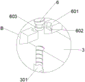
FIG. 6 is an enlarged view of the structure at A of the present invention;
FIG. 7 is an enlarged view of the structure of the present invention at B;
the reference numbers in the figures illustrate: 1. a ground surface; 2. pile columns; 3. a support bar; 301. a square groove; 302. a limiting groove; 303. fixing the ear; 304. a gear; 305. a ratchet wheel; 4. fixing the rod; 401. a rack; 402. a limiting column; 5. an adjusting handle; 501. an active pawl; 502. a check rod; 503. a non-return pawl; 504. a trapezoidal groove; 505. a trapezoidal slider; 506. a spring; 507. a fixing clip; 508. a pressure spring; 6. turning a handle; 601. a sharp-nose limiting block; 602. a circular groove; 603. a disc; 7. and (5) building a bridge.
Detailed Description
In the description of the present invention, it is to be understood that the terms "center", "longitudinal", "lateral", "length", "width", "thickness", "upper", "lower", "front", "rear", "left", "right", "vertical", "horizontal", "top", "bottom", "inner", "outer", "clockwise", "counterclockwise", and the like, indicate orientations and positional relationships based on those shown in the drawings, and are used only for convenience of description and simplicity of description, and do not indicate or imply that the equipment or element being referred to must have a particular orientation, be constructed and operated in a particular orientation, and thus, should not be considered as limiting the present invention.
In the description of the present invention, "a plurality" means two or more unless specifically defined otherwise.
In the description of the present invention, it should be noted that, unless otherwise explicitly specified or limited, the terms "mounted," "disposed," "sleeved/connected," "connected," and the like are to be construed broadly, e.g., "connected," which may be fixedly connected, detachably connected, or integrally connected; can be mechanically or electrically connected; they may be connected directly or indirectly through intervening media, or they may be interconnected between two elements. The specific meanings of the above terms in the present invention can be understood in specific cases to those skilled in the art.
Referring to fig. 1-7, the present invention provides a technical solution:
a building structure pile foundation reinforcing device comprises a ground 1, a pile 2 is arranged in the middle above the ground 1, a building bridge 7 is arranged above the pile 2, a plurality of support rods 3 are connected to the upper side and the lower side of the circumferential outer wall of the pile 2 in an annular and equidistant manner through pin shafts in a rotating manner, a square groove 301 is formed in each support rod 3, two limiting grooves 302 are symmetrically formed in the middle of the inner wall of each square groove 301, a fixing rod 4 is arranged above each support rod 3, a fixing lug 303 is fixedly arranged on the lower side of the outer end of each support rod 3, a gear 304 is rotatably connected to the upper side inside of each fixing lug 303 through a rotating shaft, a ratchet 305 is welded at the outer end of each gear 304, a regulating handle 5 is rotatably connected to the lower side inside of each fixing lug 303 through a rotating shaft, a driving pawl 501 is rotatably connected to the outer side of the lower end of the regulating handle 5 through a, the inside pressure spring 508 that is equipped with that presss from both sides of fixation clamp 507, 3 downside outer walls of bracing piece are equipped with and change 6, change 6 outer walls of bracing piece 3 and pass the bracing piece and extend to inside and be equipped with sharp mouth stopper 601 of square groove 301. Closely cooperate between the structure for the device can set up a plurality ofly simultaneously and not only improve reinforced effect, passerby's life safety has been ensured, and effectual avoided when staff need regular monitoring and maintenance reinforcement pile foundation, the regulation fastening that can not be convenient is looked over, can not carry out effectual reinforcement to it promptly, it is troublesome to bring for the staff, lead to consolidating the condition that wastes time and energy, the effect of staff's detection has been improved, can consolidate it simultaneously, the efficiency of work has been improved, and is worth promoting.
Specifically, the lower end of the fixing rod 4 penetrates through the outer wall of the supporting rod 3 to extend into the square groove 301 and be connected with the square groove in a sliding mode, two limiting columns 402 are symmetrically arranged on the outer wall of the lower end of the fixing rod 4, and the limiting columns 402 are connected with the limiting groove 302 in a sliding mode. The arrangement of the limiting column 402 enables the fixing rod 4 to be effectively limited, so that the fixing rod can only extend for a certain distance, and meanwhile, the fixing rod can be matched with different positions to fix, and the application universality is improved.
Further, a rack 401 is arranged on the upper wall of the inner side of the fixing rod 4, and the rack 401 is meshed with the gear 304. Make dead lever 4 can realize the extension, not only can adapt the fixed of different positions, can detect the reinforcement to dead lever 4 through the extension of dead lever 4 moreover.
Still further, the ratchet 305 is engaged with the driving pawl 501, and the ratchet 305 is inserted into the non-return pawl 503. So that the staff can adjust the fixing rod 4 by adjusting the handle 5 and thus the active pawl 501 rotating the ratchet 305, thus reinforcing the pile 2.
Furthermore, a trapezoidal groove 504 is formed in the check pawl 503, the trapezoidal groove 504 is slidably connected with a trapezoidal sliding block 505 arranged at the inner end of the check rod 502, and a spring 506 is arranged outside the trapezoidal sliding block 505. Set up non return pawl 503 and spacing it to cooperation spring 506 has further strengthened spacing reinforced (rfd) effect, and the effectual live time that prolongs has avoided the lax condition to appear when using for a long time, has prolonged its life.
It should be noted that the outer pressure spring 508 is tightly pressed against the outer wall of the active pawl 501, and the inner pressure spring 508 is tightly pressed against the outer wall of the check rod 502. So that the driving pawl 501 and the non-return pawl 503 are always attached to the outer wall of the circumference of the ratchet 305, thereby realizing the adjustment and the fixed limit of the ratchet.
It is worth noting that a circular groove 602 is formed in the sharp-nose limiting block 601, the circular groove 602 is rotatably connected with a circular disc 603 arranged at the lower end of the threaded end of the rotating handle 6, and the sharp-nose limiting block 601 is in insertion fit with the rack 401. Make it carry out the secondary spacingly to dead lever 4 through sharp mouth stopper 601, strengthen its fixed effect to and when the device received external striking, daily wearing and tearing or bad weather, spare parts such as ratchet 305, initiative pawl 501, non return pawl 503 then can receive erosion and harm as main spacing fixed subassembly, sharp mouth stopper 601 has then played temporary spacing fixed and guard action, makes whole device firmer.
The working principle is as follows: when the building structure pile foundation reinforcing device is needed, firstly, one end of a supporting rod 3 is rotatably connected with a groove on the outer wall of the circumference of a pile column 2 through a pin shaft, then a regulating handle 5 is swung, because the outer side of the lower end of the regulating handle 5 is rotatably connected with an active pawl 501 through a pin shaft, the inner side of the lower end of the regulating handle 5 is rotatably connected with a check rod 502 through a pin shaft, the inner side of the check rod 502 is provided with a check pawl 503, the outer side of the inner wall of a fixing lug 303 is provided with two fixing clamps 507 near the edge, the inside of the fixing clamps 507 is clamped with a pressure spring 508, the pressure spring 508 positioned at the outer side is tightly pressed with the outer wall of the active pawl 501, the pressure spring 508 positioned at the inner side is tightly pressed with the outer wall of the check rod 502, so that the active pawl 501 and the check pawl 503 are always attached to the outer wall of the circumference of a, thereby the gear 304 is rotated, because the rack 401 is engaged and connected with the gear 304, the fixed rod 4 can realize extension, which not only can be adapted to the fixation of different positions, but also can pass through the extension of the fixed rod 4, the lower end of the fixed rod 4 passes through the outer wall of the support rod 3 to extend to the inside of the square groove 301 and is connected with the square groove in a sliding way, the outer wall of the lower end of the fixed rod 4 is symmetrically provided with two limit posts 402, the limit posts 402 are connected with the limit groove 302 in a sliding way, the limit posts 402 are arranged to effectively limit the fixed rod 4, so that the fixed rod can only extend for a certain distance, and can be adapted to the fixation of different positions, thereby the application universality is improved, the other end of the fixed rod 4 is respectively connected and fixed with the building bridge 7 and the ground 1, thereby the reinforcement of the pile 2 is realized, the regulation and, the trapezoidal groove 504 is connected with a trapezoidal sliding block 505 arranged at the inner end of the check rod 502 in a sliding way, a spring 506 is arranged at the outer side of the trapezoidal sliding block 505, so that the limiting and reinforcing effect is further enhanced, meanwhile, a circular groove 602 is arranged inside the sharp mouth limiting block 601, the circular groove 602 is rotationally connected with a disc 603 arranged at the lower end of the thread end of the rotating handle 6, the sharp mouth limiting block 601 is matched with the rack 401 in an inserting way, the sharp mouth limiting block 601 is used for carrying out secondary limiting on the fixing rod 4, the fixing effect is enhanced, when the device is impacted by the outside, daily wear or bad weather, parts such as the ratchet 305, the driving pawl 501, the check pawl 503 and the like are corroded and damaged as main limiting and fixing components, the sharp mouth limiting block 601 plays a temporary limiting, fixing and protecting role, so that the whole device is firmer, the service life of the device is effectively prolonged, and the loosening condition in long-time use, the life is prolonged, the device can be used for simultaneously setting a plurality of reinforced effects, the life safety of passerby is guaranteed, the condition that the reinforcement is time-consuming and labor-consuming is caused, the detection effect of workers is improved, the reinforcement can be carried out simultaneously, the efficiency of work is improved, and the device is worthy of popularization.
The foregoing shows and describes the general principles, essential features, and advantages of the invention. It will be understood by those skilled in the art that the present invention is not limited to the embodiments described above, and the preferred embodiments of the present invention are described in the above embodiments and the description, and are not intended to limit the present invention. The scope of the invention is defined by the appended claims and equivalents thereof.
Claims (7)
1. The utility model provides a building structure pile foundation reinforcing apparatus, includes ground (1), its characterized in that: the building bridge is characterized in that a pile (2) is arranged in the middle of the upper portion of the ground (1), a building bridge (7) is arranged above the pile (2), a plurality of supporting rods (3) are connected to the upper portion and the lower portion of the circumferential outer wall of the pile (2) in an annular and equidistant rotating mode through pin shafts, a square groove (301) is formed in the supporting rods (3), two limiting grooves (302) are symmetrically formed in the middle of the inner wall of the square groove (301), a fixing rod (4) is arranged above the supporting rods (3), a fixing lug (303) is fixedly arranged on the lower side of the outer end of each supporting rod (3), a gear (304) is rotatably connected to the upper side of the inner portion of each fixing lug (303) through a rotating shaft, a ratchet (305) is welded to the outer end of the gear (304), an adjusting handle (5) is rotatably connected to the lower side, adjust (5) lower extreme inboard and be connected with non return pole (502) through the round pin axle rotation, non return pole (502) inboard is equipped with non return pawl (503), fixed ear (303) inner wall outside is close to the edge and is equipped with two fixation clamps (507), the inside pressure spring (508) that are equipped with that press from both sides of fixation clamp (507), bracing piece (3) downside outer wall is equipped with changes (6), change (6) screw thread end and pass bracing piece (3) outer wall and extend to square groove (301) inside and be equipped with sharp mouth stopper (601).
2. The building structure pile foundation reinforcing apparatus of claim 1, wherein: the lower end of the fixing rod (4) penetrates through the outer wall of the supporting rod (3) to extend into the square groove (301) and be connected with the square groove in a sliding mode, two limiting columns (402) are symmetrically arranged on the outer wall of the lower end of the fixing rod (4), and the limiting columns (402) are connected with the limiting groove (302) in a sliding mode.
3. The building structure pile foundation reinforcing apparatus of claim 1, wherein: the upper wall of the inner side of the fixed rod (4) is provided with a rack (401), and the rack (401) is meshed with the gear (304).
4. The building structure pile foundation reinforcing apparatus of claim 1, wherein: the ratchet wheel (305) is in meshed connection with the driving pawl (501), and the ratchet wheel (305) is in inserted fit with the non-return pawl (503).
5. The building structure pile foundation reinforcing apparatus of claim 1, wherein: a trapezoidal groove (504) is formed in the check pawl (503), the trapezoidal groove (504) is in sliding connection with a trapezoidal sliding block (505) arranged at the inner end of the check rod (502), and a spring (506) is arranged on the outer side of the trapezoidal sliding block (505).
6. The building structure pile foundation reinforcing apparatus of claim 1, wherein: the pressure spring (508) positioned on the outer side is tightly pressed with the outer wall of the active pawl (501), and the pressure spring (508) positioned on the inner side is tightly pressed with the outer wall of the check rod (502).
7. The building structure pile foundation reinforcing apparatus of claim 1, wherein: round groove (602) have been seted up to sharp mouth stopper (601) inside, round groove (602) with disc (603) that commentaries on classics (6) thread end lower extreme set up rotate to be connected, sharp mouth stopper (601) and rack (401) cooperation of pegging graft.
Priority Applications (1)
| Application Number | Priority Date | Filing Date | Title |
|---|---|---|---|
| CN202110255102.8A CN112982389A (en) | 2021-03-09 | 2021-03-09 | Building structure pile foundation reinforcing apparatus |
Applications Claiming Priority (1)
| Application Number | Priority Date | Filing Date | Title |
|---|---|---|---|
| CN202110255102.8A CN112982389A (en) | 2021-03-09 | 2021-03-09 | Building structure pile foundation reinforcing apparatus |
Publications (1)
| Publication Number | Publication Date |
|---|---|
| CN112982389A true CN112982389A (en) | 2021-06-18 |
Family
ID=76336092
Family Applications (1)
| Application Number | Title | Priority Date | Filing Date |
|---|---|---|---|
| CN202110255102.8A Pending CN112982389A (en) | 2021-03-09 | 2021-03-09 | Building structure pile foundation reinforcing apparatus |
Country Status (1)
| Country | Link |
|---|---|
| CN (1) | CN112982389A (en) |
Citations (4)
| Publication number | Priority date | Publication date | Assignee | Title |
|---|---|---|---|---|
| CN104320054A (en) * | 2014-11-03 | 2015-01-28 | 合肥成科电子科技有限公司 | Adjustable photovoltaic solar support |
| CN209585085U (en) * | 2018-11-16 | 2019-11-05 | 安徽省淮阜路桥工程建设有限公司 | A kind of bracing means for Road Bridge Pile Foundation |
| CN210712826U (en) * | 2019-10-11 | 2020-06-09 | 周宏� | Pile foundation reinforcing apparatus for road and bridge |
| CN211922338U (en) * | 2020-03-03 | 2020-11-13 | 张己存 | Highway bridge pile foundation reinforcing apparatus |
-
2021
- 2021-03-09 CN CN202110255102.8A patent/CN112982389A/en active Pending
Patent Citations (4)
| Publication number | Priority date | Publication date | Assignee | Title |
|---|---|---|---|---|
| CN104320054A (en) * | 2014-11-03 | 2015-01-28 | 合肥成科电子科技有限公司 | Adjustable photovoltaic solar support |
| CN209585085U (en) * | 2018-11-16 | 2019-11-05 | 安徽省淮阜路桥工程建设有限公司 | A kind of bracing means for Road Bridge Pile Foundation |
| CN210712826U (en) * | 2019-10-11 | 2020-06-09 | 周宏� | Pile foundation reinforcing apparatus for road and bridge |
| CN211922338U (en) * | 2020-03-03 | 2020-11-13 | 张己存 | Highway bridge pile foundation reinforcing apparatus |
Non-Patent Citations (1)
| Title |
|---|
| 丁洪生等: "《机械原理》", 31 December 2016 * |
Similar Documents
| Publication | Publication Date | Title |
|---|---|---|
| CN110254465B (en) | Anti-sliding device of freight train | |
| CN112982389A (en) | Building structure pile foundation reinforcing apparatus | |
| CN209802543U (en) | Soil pressure box pre-embedding device for monitoring soil pressure of tunnel | |
| EP0028662A2 (en) | Sign-supporting structure with panel holding bushes | |
| CN214832745U (en) | Retaining wall device for foundation pit support | |
| CN212272038U (en) | Cleaning machine for pile mouth of prestressed pipe pile | |
| CN211498547U (en) | Windshield for highway bridge | |
| CN215215521U (en) | Monitoring device for urban road intersection traffic flow | |
| CN213476680U (en) | Warning device is used in highway engineering construction | |
| CN212175614U (en) | Town road guardrail | |
| CN220469556U (en) | Meadow seals and educates security fence | |
| CN211369802U (en) | Safety device for highway engineering | |
| CN217299770U (en) | Anti-toppling device for building construction scaffold | |
| CN217556824U (en) | Municipal water conservancy flood prevention device convenient to equipment | |
| CN219622431U (en) | Traffic guiding guardrail | |
| CN220848056U (en) | Node structure for connecting steel structure with outer wall | |
| CN111287183A (en) | Road construction's pile device | |
| CN218961770U (en) | Detachable simple and easy horse art obstacle stand | |
| CN218203968U (en) | Novel deceleration strip structure | |
| CN214786300U (en) | Reinforcing bar protection canopy regularization device | |
| CN212957982U (en) | Dyke warning fence for hydraulic engineering | |
| CN216130599U (en) | Protective cover plate for opening | |
| CN212840559U (en) | Indoor and outdoor monitoring device with alarm function | |
| CN220599435U (en) | Highway maintenance rail with location structure | |
| CN220377899U (en) | Maintenance geotechnical cloth fixing device |
Legal Events
| Date | Code | Title | Description |
|---|---|---|---|
| PB01 | Publication | ||
| PB01 | Publication | ||
| SE01 | Entry into force of request for substantive examination | ||
| SE01 | Entry into force of request for substantive examination | ||
| RJ01 | Rejection of invention patent application after publication | ||
| RJ01 | Rejection of invention patent application after publication |
Application publication date: 20210618 |