CN112956320A - Plant growth monitoring device for agricultural internet of things - Google Patents
Plant growth monitoring device for agricultural internet of things Download PDFInfo
- Publication number
- CN112956320A CN112956320A CN202110126601.7A CN202110126601A CN112956320A CN 112956320 A CN112956320 A CN 112956320A CN 202110126601 A CN202110126601 A CN 202110126601A CN 112956320 A CN112956320 A CN 112956320A
- Authority
- CN
- China
- Prior art keywords
- stirring
- things
- shaft
- monitoring device
- plant growth
- Prior art date
- Legal status (The legal status is an assumption and is not a legal conclusion. Google has not performed a legal analysis and makes no representation as to the accuracy of the status listed.)
- Pending
Links
Images


Classifications
-
- A—HUMAN NECESSITIES
- A01—AGRICULTURE; FORESTRY; ANIMAL HUSBANDRY; HUNTING; TRAPPING; FISHING
- A01C—PLANTING; SOWING; FERTILISING
- A01C23/00—Distributing devices specially adapted for liquid manure or other fertilising liquid, including ammonia, e.g. transport tanks or sprinkling wagons
- A01C23/04—Distributing under pressure; Distributing mud; Adaptation of watering systems for fertilising-liquids
- A01C23/047—Spraying of liquid fertilisers
-
- B—PERFORMING OPERATIONS; TRANSPORTING
- B02—CRUSHING, PULVERISING, OR DISINTEGRATING; PREPARATORY TREATMENT OF GRAIN FOR MILLING
- B02C—CRUSHING, PULVERISING, OR DISINTEGRATING IN GENERAL; MILLING GRAIN
- B02C15/00—Disintegrating by milling members in the form of rollers or balls co-operating with rings or discs
- B02C15/08—Mills with balls or rollers centrifugally forced against the inner surface of a ring, the balls or rollers of which are driven by a centrally arranged member
-
- B—PERFORMING OPERATIONS; TRANSPORTING
- B05—SPRAYING OR ATOMISING IN GENERAL; APPLYING FLUENT MATERIALS TO SURFACES, IN GENERAL
- B05B—SPRAYING APPARATUS; ATOMISING APPARATUS; NOZZLES
- B05B15/00—Details of spraying plant or spraying apparatus not otherwise provided for; Accessories
- B05B15/20—Arrangements for agitating the material to be sprayed, e.g. for stirring, mixing or homogenising
- B05B15/25—Arrangements for agitating the material to be sprayed, e.g. for stirring, mixing or homogenising using moving elements, e.g. rotating blades
-
- B—PERFORMING OPERATIONS; TRANSPORTING
- B05—SPRAYING OR ATOMISING IN GENERAL; APPLYING FLUENT MATERIALS TO SURFACES, IN GENERAL
- B05B—SPRAYING APPARATUS; ATOMISING APPARATUS; NOZZLES
- B05B3/00—Spraying or sprinkling apparatus with moving outlet elements or moving deflecting elements
- B05B3/14—Spraying or sprinkling apparatus with moving outlet elements or moving deflecting elements with oscillating elements; with intermittent operation
-
- H—ELECTRICITY
- H04—ELECTRIC COMMUNICATION TECHNIQUE
- H04N—PICTORIAL COMMUNICATION, e.g. TELEVISION
- H04N7/00—Television systems
- H04N7/18—Closed-circuit television [CCTV] systems, i.e. systems in which the video signal is not broadcast
- H04N7/181—Closed-circuit television [CCTV] systems, i.e. systems in which the video signal is not broadcast for receiving images from a plurality of remote sources
Abstract
The invention relates to the technical field of monitoring of Internet of things, and discloses a plant growth monitoring device for agricultural Internet of things, which comprises a plate body, wherein a stirring box is arranged on the plate body, a stirring assembly is arranged inside the stirring box, a driving assembly is arranged on a top plate of the stirring box, the driving assembly comprises a driving motor and a transmission shaft, a swinging assembly is arranged at the top end of the transmission shaft, the swinging assembly comprises an I-shaped beam and a sliding plate, a spray head is rotatably connected onto the sliding plate and is connected with the stirring assembly through a water pipe, and a camera is arranged below a guide plate. Thereby maximally ensuring the growth state of the plant.
Description
Technical Field
The invention relates to the technical field of monitoring of Internet of things, in particular to a plant growth monitoring device for an agricultural Internet of things.
Background
In the in-process of vegetation, the plant foliage surface can lead to the blade to turn yellow, wither and other problems because multiple factor, and this just needs to apply the leaf fertilizer and promotes vegetation, and the traditional fertilization mode is local spraying, though reached the effect, the quantity is too big, is unfavorable for practicing thrift the cost, improves economic benefits, and inconvenient feeding in raw material to inside in addition stirs more troublesome, can not realize the fixed point and spray.
Disclosure of Invention
The invention aims to provide a plant growth monitoring device for an agricultural Internet of things, and aims to solve the problems in the background technology.
In order to achieve the purpose, the invention provides the following technical scheme:
a plant growth monitoring device for an agricultural Internet of things comprises a plate body, wherein a stirring tank is fixedly mounted on the plate body, the inclined plane of the bottom plate of the stirring tank is a slope surface, a stirring assembly is arranged in the stirring tank and comprises a stirring shaft and a plurality of blades which are equidistantly distributed on the surface of the stirring shaft, the bottom of the stirring shaft is fixedly connected with a cone matched with the inclined plane of the stirring tank, a feeding pipe is fixedly mounted at the top of one side of the stirring tank, a tool box is fixedly connected onto the top plate of the stirring tank, a driving assembly is arranged in the tool box and comprises a driving motor and a transmission shaft, the driving motor is in transmission connection with a gear shaft, the top end of the gear shaft is rotatably connected onto the tool box, the gear shaft is meshed with a driven wheel, the driven wheel is fixedly mounted at the bottom of the transmission shaft, the swing subassembly is installed on the top of transmission shaft, the swing subassembly includes the I-beam and rotates the carousel of connecting on the I-beam, the carousel is connected with the transmission shaft transmission of bottom, the eccentric spud pile that is provided with on the carousel, it is connected with the pendulum rod to rotate on the crossbeam of I-beam, the middle part of pendulum rod is seted up slottedly, the inslot sliding connection spud pile, the free end of pendulum rod articulates there is the movable rod, the one end of movable rod articulates there is the slide, slide and deflector sliding connection, the blend stop is installed to the inboard of deflector, the lower surface of slide rotates and is connected with the shower nozzle, the inside of shower nozzle is hollow structure, set up the hole that a plurality of annular distribute on the side of shower nozzle, the shower nozzle passes through the water pipe and is connected with stirring assembly, the both ends fixed mounting.
As a further scheme of the invention: one side of the stirring box is connected with an external water pump through a water pipe, and the water pipe is provided with a regulating valve.
As a still further scheme of the invention: the protective cover is provided with a drainage cover which is designed in a conical shape.
As a still further scheme of the invention: fixedly connected with arc pole on the side of plate body, the top of arc pole is rotated and is connected with the push rod, and the installation slope is provided with the pull rod on the arc pole.
As a still further scheme of the invention: and diamond anti-skid grains are arranged on the outer cylindrical surface of the push rod.
As a still further scheme of the invention: the bottom fixed mounting of plate body has the support of locking function, rotates on the support to be connected with the wheel.
As a still further scheme of the invention: and a PLC controller is fixedly installed on the inner side of the plate body.
Compared with the prior art, the invention has the beneficial effects that: this device overall design is reasonable, compact structure, is convenient for install and removes, and the camera is at the in-process that advances, can be accurate detect the blade surface of plant, and the cone rolls along the inclined plane and will pile up the fertilizer in the bottom and pulverize in the stirring subassembly, and the paddle carries out abundant stirring to mixed solution, guarantees the homogeneous mixing of solution, and the swing subassembly drives the shower nozzle and realizes the accurate spraying of fixed point to the plant blade surface to ensure the growth state of plant in the at utmost.
Drawings
Fig. 1 is a schematic structural diagram of a plant growth monitoring device for the internet of things of agriculture.
Fig. 2 is a schematic structural diagram of a device body in the plant growth monitoring device for the agricultural internet of things.
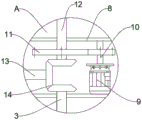
Fig. 3 is a schematic structural diagram of a in fig. 1.
Fig. 4 is a schematic structural diagram of a guide plate in a plant growth monitoring device for the internet of things of agriculture.
Fig. 5 is a schematic structural diagram of a swing assembly in a plant growth monitoring device for the internet of things of agriculture.
In the figure: the plate body 1, the agitator tank 2, (mixing) shaft 3, paddle 4, cone 5, inlet pipe 6, water pipe 7, toolbox 8, driving motor 9, gear shaft 10, follow driving wheel 11, transmission shaft 12, pivot 13, gear train 14, I-beam 15, carousel 16, pendulum rod 17, movable rod 18, slide 19, shower nozzle 20, deflector 21, triangular cone 22, safety cover 23, camera 24, drainage cover 25, arc pole 26, push rod 27, pull rod 28, support 29, PLC controller 30.
Detailed Description
In order to make the objects, technical solutions and advantages of the present invention more apparent, the present invention is described in further detail below with reference to the accompanying drawings and embodiments. It should be understood that the specific embodiments described herein are merely illustrative of the invention and are not intended to limit the invention.
Specific implementations of the present invention are described in detail below with reference to specific embodiments.
As shown in fig. 1 and 3 to 5, a structure diagram of a plant growth monitoring device for an agricultural internet of things provided by an embodiment of the invention comprises a plate body 1, a stirring tank 2 is fixedly installed on the plate body 1, an inclined plane of a bottom plate of the stirring tank 2 is a slope, a stirring assembly is arranged inside the stirring tank 2, the stirring assembly comprises a stirring shaft 3 and a plurality of blades 4 which are distributed on the surface of the stirring shaft 3 at equal intervals, a cone 5 which is matched with the inclined plane of the stirring tank 2 is fixedly connected to the bottom of the stirring shaft 3, a feeding pipe 6 is fixedly installed at the top of one side of the stirring tank 2, the other side of the stirring tank 2 is connected with an external water pump through a water pipe 7, an adjusting valve is installed on the water pipe 7, a tool box 8 is fixedly connected to the top plate of the stirring tank 2, a driving assembly is arranged inside the tool box 8, the, the top end of a gear shaft 10 is rotatably connected on a tool box 8, the gear shaft 10 is meshed with a driven wheel 11, the driven wheel 11 is fixedly arranged at the bottom of a transmission shaft 12, the transmission shaft 12 is in transmission connection with a rotating shaft 13 which is rotatably connected on the inner side of the tool box 8 through a gear set 14, the rotating shaft 13 is meshed with a stirring shaft 3 through the gear set 14, the top end of the transmission shaft 12 is provided with a swinging assembly, the swinging assembly comprises an I-shaped beam 15 and a rotating disc 16 which is rotatably connected on the I-shaped beam 15, the rotating disc 16 is in transmission connection with the transmission shaft 12 at the bottom, a fixing pile is eccentrically arranged on the rotating disc 16, a swinging rod 17 is rotatably connected on a cross beam of the I-shaped beam 15, the middle part of the swinging rod 17 is provided with a groove, the fixing pile is slidably connected in the groove, the, slide 19's lower surface rotates and is connected with shower nozzle 20, shower nozzle 20's inside is hollow structure, the hole that a plurality of annular distribute has been seted up on shower nozzle 20's the side, shower nozzle 20 leads to pipe 7 and is connected with the stirring subassembly, the both ends fixed mounting of deflector 21 has set-square 22, install safety cover 23 on set-square 22's the inclined plane, the inside wall of safety cover 23 is provided with camera 24, be provided with flow guide cover 25 on the safety cover 23, flow guide cover 25 toper design, be convenient for fall the liquid rapid drip on safety cover 23. When the device is used, the device moves forwards, in the advancing process, the camera 24 detects the plant leaf surfaces on two sides of the device, when the poor growth state of the leaves is detected, the plant growth is promoted by spraying a medicament on the leaf surfaces, wherein the driving motor 9 works to drive the gear shaft 10 to rotate, the gear shaft 10 drives the transmission shaft 12 to rotate through the driven wheel 11, on one hand, the transmission shaft 12 drives the rotating shaft 13 to rotate along the side wall of the tool box 8 through the gear set 14, the rotating shaft 13 drives the stirring shaft 3 to rotate, the paddle 4 and the cone 5 rotate along with the stirring shaft 3, wherein the cone 5 rolls along the inclined plane to crush the fertilizer accumulated at the bottom, the paddle 4 fully stirs the mixed solution to ensure that the concentration of the sprayed solution is within a certain range, the external water pump guides the mixed solution into the spray head 20 along the water pipe 7, and simultaneously, in the process of rotating the fixed pile on the turntable 16, the swing rod 17 is pulled to swing along the center of the cross beam of the I-beam 15, the swing rod 17 drives the movable rod 18 to do plane swing, the movable rod 18 pulls the sliding plate 19 to slide along the guide plate 21, the spray head 20 moves along with the sliding plate 19, and in the process of rotating, solution is sprayed to the leaf surface of the plant at a fixed point.
As shown in fig. 2, as a preferred embodiment of the present invention, an arc rod 26 is fixedly connected to a side surface of a plate body 1, a push rod 27 is rotatably connected to a top portion of the arc rod 26, a diamond-shaped anti-slip pattern is provided on an outer cylindrical surface of the push rod 27, a pull rod 28 is obliquely installed on the arc rod 26, a bracket 29 having a locking function is fixedly installed at a bottom portion of the plate body 1, a wheel is rotatably connected to the bracket 29, a PLC controller 30 is fixedly installed on an inner side of the plate body 1, and as a preferred embodiment, the PLC controller 30 is of a siemens 600 series type, and since the embodiment does not improve an internal structure, a circuit, and the like of the PLC controller 30, a specific operation principle, a control process, and the like of the PLC controller 30 are. When the anti-skid plate is used, the push rod 27 is pushed, the arc-shaped rod 26 pushes the plate body 1 to move forwards, when the plate body does not need to move, the pedal of the side plate of the support 29 is stepped by feet to lock the wheel, and the diamond anti-skid lines arranged on the push rod 27 ensure that acting force can be conveniently applied when the plate body is held, so that the plate body can not slide in the pushing process.
The working principle of the invention is as follows: when the device is used, the push rod 27 is pushed, the arc-shaped rod 26 pushes the plate body 1 to move forwards, the device moves forwards, in the advancing process, the camera 24 detects plant leaf surfaces on two sides of the device, when the poor growth state of the leaves is detected, a medicament is sprayed on the leaf surfaces, the growth of plants is promoted, the driving motor 9 works to drive the gear shaft 10 to rotate, the gear shaft 10 drives the transmission shaft 12 to rotate through the driven wheel 11, on one hand, the transmission shaft 12 drives the rotating shaft 13 to rotate along the side wall of the tool box 8 through the gear set 14, the rotating shaft 13 drives the stirring shaft 3 to rotate, the blades 4 and the cone 5 rotate along with the stirring shaft 3, the cone 5 rolls along the inclined plane to crush the fertilizer accumulated at the bottom, the blades 4 fully stir the mixed solution, the concentration of the sprayed solution is ensured to be within a certain range, the external water pump guides the mixed, meanwhile, the transmission shaft 12 drives the rotary table 16 to rotate, the swing rod 17 is pulled to swing along the center of the cross beam of the I-beam 15 in the process of rotating the fixing pile on the rotary table 16, the swing rod 17 drives the movable rod 18 to swing in a plane, the movable rod 18 pulls the sliding plate 19 to slide along the guide plate 21, the spray head 20 moves along with the sliding plate 19 and sprays solution to the leaf surface of the plant at a fixed point in the rotating process, when the solution does not need to move, the pedal of the side plate of the bracket 29 is stepped by feet to lock the wheels, and the rhombic anti-slip grains arranged on the push rod 27 ensure that when the solution is held, acting force is convenient to apply, and the situation that the.
It will be evident to those skilled in the art that the invention is not limited to the details of the foregoing illustrative embodiments, and that the present invention may be embodied in other specific forms without departing from the spirit or essential attributes thereof. The present embodiments are therefore to be considered in all respects as illustrative and not restrictive, the scope of the invention being indicated by the appended claims rather than by the foregoing description, and all changes which come within the meaning and range of equivalency of the claims are therefore intended to be embraced therein. Any reference sign in a claim should not be construed as limiting the claim concerned.
In the description of the present invention, it is to be understood that the terms "central", "longitudinal", "lateral", "up", "down", "front", "back", "left", "right", "vertical", "horizontal", "top", "bottom", "inner", "outer", and the like, indicate orientations and positional relationships based on the orientations and positional relationships shown in the drawings, are only used for convenience in describing the invention and for simplicity in description, and do not imply that the referred device or element must have a specific orientation, be constructed and operated in a specific orientation, and thus, should not be construed as limiting the invention. Furthermore, the terms "first," "second," and the like are used for descriptive purposes only and are not to be construed as indicating or implying relative importance or implying any number of technical features indicated. Thus, a feature defined as "first," "second," etc. may explicitly or implicitly include one or more of that feature. In the description of the present invention, "a plurality" means two or more unless otherwise specified.
Furthermore, it should be understood that although the present description refers to embodiments, not every embodiment contains only a single technical solution, and such description of the description is only for clarity, and those skilled in the art should make the description as a whole, and the technical solutions in the embodiments may be appropriately combined to form other embodiments that those skilled in the art can understand.
Claims (7)
1. The plant growth monitoring device for the agricultural Internet of things comprises a plate body (1) and is characterized in that a stirring box (2) is fixedly installed on the plate body (1), the inclined plane of the bottom plate of the stirring box (2) is a slope surface, a stirring assembly is arranged inside the stirring box (2), the stirring assembly comprises a stirring shaft (3) and a plurality of blades (4) which are distributed on the surface of the stirring shaft (3) at equal intervals, the bottom of the stirring shaft (3) is fixedly connected with a cone (5) matched with the inclined plane of the stirring box (2), the top of one side of the stirring box (2) is fixedly provided with a feeding pipe (6), a tool box (8) is fixedly connected onto the top plate of the stirring box (2), a driving assembly is arranged inside the tool box (8), the driving assembly comprises a driving motor (9) and a transmission shaft (12), the driving motor (9) is in transmission connection with a gear shaft (10), the top end of the, the gear shaft (10) is meshed with a driven wheel (11), the driven wheel (11) is fixedly arranged at the bottom of a transmission shaft (12), the transmission shaft (12) is in transmission connection with a rotating shaft (13) which is rotatably connected to the inner side of a tool box (8) through a gear set (14), the rotating shaft (13) is meshed with a stirring shaft (3) through the gear set (14), a swinging assembly is arranged at the top end of the transmission shaft (12), the swinging assembly comprises an I-shaped beam (15) and a rotating disc (16) which is rotatably connected to the I-shaped beam (15), the rotating disc (16) is in transmission connection with the transmission shaft (12) at the bottom, a fixed pile is eccentrically arranged on the rotating disc (16), a swinging rod (17) is rotatably connected to the beam of the I-shaped beam (15), a groove is formed in the middle of the swinging rod (17), the fixed pile is slidably connected in the groove, a movable rod (18, slide (19) and deflector (21) sliding connection, the blend stop is installed to the inboard of deflector (21), the lower surface of slide (19) rotates and is connected with shower nozzle (20), the inside of shower nozzle (20) is hollow structure, the hole that a plurality of annular distribute has been seted up on the side of shower nozzle (20), shower nozzle (20) are connected with the stirring subassembly through water pipe (7), the both ends fixed mounting of deflector (21) has triangular cone (22), install safety cover (23) on the inclined plane of triangular cone (22), the inside wall of safety cover (23) is provided with camera (24).
2. The plant growth monitoring device for the agricultural internet of things as claimed in claim 1, wherein one side of the stirring tank (2) is connected with an external water pump through a water pipe (7), and the water pipe (7) is provided with an adjusting valve.
3. The plant growth monitoring device for the Internet of things of agriculture is characterized in that a drainage cover (25) is arranged on the protection cover (23), and the drainage cover (25) is in a conical design.
4. The plant growth monitoring device for the agricultural internet of things as claimed in claim 1, wherein an arc-shaped rod (26) is fixedly connected to the side surface of the plate body (1), a push rod (27) is rotatably connected to the top of the arc-shaped rod (26), and a pull rod (28) is obliquely arranged on the arc-shaped rod (26).
5. The plant growth monitoring device for the agricultural internet of things as claimed in claim 4, wherein diamond-shaped anti-slip lines are arranged on the outer cylindrical surface of the push rod (27).
6. The plant growth monitoring device for the Internet of things of agriculture is characterized in that a support (29) with a locking function is fixedly installed at the bottom of the plate body (1), and wheels are rotatably connected to the support (29).
7. The plant growth monitoring device for the Internet of things of agriculture according to any one of claims 1-2, wherein a PLC (programmable logic controller) is fixedly installed on the inner side of the plate body (1).
Priority Applications (1)
| Application Number | Priority Date | Filing Date | Title |
|---|---|---|---|
| CN202110126601.7A CN112956320A (en) | 2021-01-29 | 2021-01-29 | Plant growth monitoring device for agricultural internet of things |
Applications Claiming Priority (1)
| Application Number | Priority Date | Filing Date | Title |
|---|---|---|---|
| CN202110126601.7A CN112956320A (en) | 2021-01-29 | 2021-01-29 | Plant growth monitoring device for agricultural internet of things |
Publications (1)
| Publication Number | Publication Date |
|---|---|
| CN112956320A true CN112956320A (en) | 2021-06-15 |
Family
ID=76273465
Family Applications (1)
| Application Number | Title | Priority Date | Filing Date |
|---|---|---|---|
| CN202110126601.7A Pending CN112956320A (en) | 2021-01-29 | 2021-01-29 | Plant growth monitoring device for agricultural internet of things |
Country Status (1)
| Country | Link |
|---|---|
| CN (1) | CN112956320A (en) |
Cited By (4)
| Publication number | Priority date | Publication date | Assignee | Title |
|---|---|---|---|---|
| CN113698214A (en) * | 2021-09-16 | 2021-11-26 | 青岛尊龙耐火材料有限公司 | Special heat-insulating refractory material and processing equipment thereof |
| CN114354606A (en) * | 2022-03-21 | 2022-04-15 | 广东省农业科学院植物保护研究所 | System and method for monitoring influence of virus on plant |
| CN115349341A (en) * | 2022-07-20 | 2022-11-18 | 湖南科技学院 | Intelligent vegetable foliar fertilizer fixed-point spraying equipment |
| CN115812565A (en) * | 2022-11-24 | 2023-03-21 | 东北农业大学 | Automatic irrigation device based on agricultural remote sensing technology |
Citations (8)
| Publication number | Priority date | Publication date | Assignee | Title |
|---|---|---|---|---|
| GB1034114A (en) * | 1963-03-28 | 1966-06-29 | Johnson March Corp | Improvements in method and apparatus for mixing pulverulent material or pulverulent material with liquid |
| CN109121638A (en) * | 2018-08-27 | 2019-01-04 | 张吉祥 | A kind of agricultural planting fertigation integrated device |
| CN110393074A (en) * | 2018-04-24 | 2019-11-01 | 佛山市嘉懿行农业科技有限公司 | A kind of wisdom agricultural Internet of Things liquid manure all-in-one machine |
| CN110402680A (en) * | 2019-09-11 | 2019-11-05 | 陈彩霞 | A kind of weeding apparatus for agricultural planting |
| CN210275638U (en) * | 2019-06-11 | 2020-04-10 | 刘辉 | A spout medicine device for gardens |
| CN111034444A (en) * | 2019-12-24 | 2020-04-21 | 王彩荣 | Safe water spraying device for livestock breeding grassland |
| CN211430064U (en) * | 2019-11-23 | 2020-09-08 | 佛山市国众智能科技工程有限公司 | Forestry is bred with rich selenium water fertilizer mixing arrangement |
| CN111955324A (en) * | 2020-06-07 | 2020-11-20 | 长乐巧通工业设计有限公司 | Adjustable miniature irrigation device for agricultural planting |
-
2021
- 2021-01-29 CN CN202110126601.7A patent/CN112956320A/en active Pending
Patent Citations (8)
| Publication number | Priority date | Publication date | Assignee | Title |
|---|---|---|---|---|
| GB1034114A (en) * | 1963-03-28 | 1966-06-29 | Johnson March Corp | Improvements in method and apparatus for mixing pulverulent material or pulverulent material with liquid |
| CN110393074A (en) * | 2018-04-24 | 2019-11-01 | 佛山市嘉懿行农业科技有限公司 | A kind of wisdom agricultural Internet of Things liquid manure all-in-one machine |
| CN109121638A (en) * | 2018-08-27 | 2019-01-04 | 张吉祥 | A kind of agricultural planting fertigation integrated device |
| CN210275638U (en) * | 2019-06-11 | 2020-04-10 | 刘辉 | A spout medicine device for gardens |
| CN110402680A (en) * | 2019-09-11 | 2019-11-05 | 陈彩霞 | A kind of weeding apparatus for agricultural planting |
| CN211430064U (en) * | 2019-11-23 | 2020-09-08 | 佛山市国众智能科技工程有限公司 | Forestry is bred with rich selenium water fertilizer mixing arrangement |
| CN111034444A (en) * | 2019-12-24 | 2020-04-21 | 王彩荣 | Safe water spraying device for livestock breeding grassland |
| CN111955324A (en) * | 2020-06-07 | 2020-11-20 | 长乐巧通工业设计有限公司 | Adjustable miniature irrigation device for agricultural planting |
Cited By (5)
| Publication number | Priority date | Publication date | Assignee | Title |
|---|---|---|---|---|
| CN113698214A (en) * | 2021-09-16 | 2021-11-26 | 青岛尊龙耐火材料有限公司 | Special heat-insulating refractory material and processing equipment thereof |
| CN114354606A (en) * | 2022-03-21 | 2022-04-15 | 广东省农业科学院植物保护研究所 | System and method for monitoring influence of virus on plant |
| CN115349341A (en) * | 2022-07-20 | 2022-11-18 | 湖南科技学院 | Intelligent vegetable foliar fertilizer fixed-point spraying equipment |
| CN115349341B (en) * | 2022-07-20 | 2024-02-02 | 湖南科技学院 | Intelligent vegetable foliar fertilizer fixed-point spraying equipment |
| CN115812565A (en) * | 2022-11-24 | 2023-03-21 | 东北农业大学 | Automatic irrigation device based on agricultural remote sensing technology |
Similar Documents
| Publication | Publication Date | Title |
|---|---|---|
| CN112956320A (en) | Plant growth monitoring device for agricultural internet of things | |
| CN111448973A (en) | Oscillating irrigation and water conservancy irrigation device | |
| CN213961156U (en) | Highway green curing means that plants | |
| CN211129273U (en) | Expressway green plant maintenance vehicle | |
| CN218360018U (en) | Swing type plant leaf surface blocking agent spraying machine | |
| CN217037964U (en) | Accurate irrigation robot of field liquid manure integration | |
| CN215648578U (en) | Agricultural irrigation device | |
| CN113853917A (en) | Water and fertilizer integrated water-saving irrigation device | |
| CN108551831A (en) | A kind of dual-purpose type work package of intelligence horticultural tractor | |
| CN212753135U (en) | Accurate device that waters of drought ground economic crop root system | |
| CN210869158U (en) | Irrigation equipment is used in crops cultivation | |
| CN113748816A (en) | Assembled hydraulic engineering uses multi-functional irrigation machine | |
| CN209882556U (en) | Photovoltaic fertilizer injection unit for irrigation | |
| CN109496789B (en) | Farmland irrigation equipment for three-position conveying of easily hardened ground | |
| CN112753348A (en) | Rice planting mixes fertilization integration equipment | |
| CN115024073B (en) | Agricultural water and fertilizer irrigation device and method | |
| CN220776866U (en) | Municipal afforestation area irrigation equipment | |
| CN216018318U (en) | Irrigation device for water and soil conservation | |
| CN220897201U (en) | Agricultural machine fertilizer injection unit | |
| CN217985989U (en) | Integrative wisdom irrigation equipment of flower planting liquid manure | |
| CN218007472U (en) | Irrigation equipment is used in protection of ploughing | |
| CN213848066U (en) | Agricultural is with multi-functional irrigation equipment | |
| CN211746437U (en) | Irrigation sprinkler for irrigation and water conservancy project | |
| CN215012913U (en) | Pesticide irrigation equipment for farming | |
| CN217088664U (en) | Fertilizer injection unit for planting traditional Chinese medicinal materials |
Legal Events
| Date | Code | Title | Description |
|---|---|---|---|
| PB01 | Publication | ||
| PB01 | Publication | ||
| SE01 | Entry into force of request for substantive examination | ||
| SE01 | Entry into force of request for substantive examination | ||
| RJ01 | Rejection of invention patent application after publication | ||
| RJ01 | Rejection of invention patent application after publication |
Application publication date: 20210615 |