CN112942855A - Large brick clamping device for building wall and using method thereof - Google Patents
Large brick clamping device for building wall and using method thereof Download PDFInfo
- Publication number
- CN112942855A CN112942855A CN202110195611.6A CN202110195611A CN112942855A CN 112942855 A CN112942855 A CN 112942855A CN 202110195611 A CN202110195611 A CN 202110195611A CN 112942855 A CN112942855 A CN 112942855A
- Authority
- CN
- China
- Prior art keywords
- fixedly connected
- plates
- clamping
- plate
- brick
- Prior art date
- Legal status (The legal status is an assumption and is not a legal conclusion. Google has not performed a legal analysis and makes no representation as to the accuracy of the status listed.)
- Granted
Links
Images


Classifications
-
- E—FIXED CONSTRUCTIONS
- E04—BUILDING
- E04G—SCAFFOLDING; FORMS; SHUTTERING; BUILDING IMPLEMENTS OR AIDS, OR THEIR USE; HANDLING BUILDING MATERIALS ON THE SITE; REPAIRING, BREAKING-UP OR OTHER WORK ON EXISTING BUILDINGS
- E04G21/00—Preparing, conveying, or working-up building materials or building elements in situ; Other devices or measures for constructional work
- E04G21/14—Conveying or assembling building elements
- E04G21/16—Tools or apparatus
Landscapes
- Engineering & Computer Science (AREA)
- Architecture (AREA)
- Mechanical Engineering (AREA)
- Civil Engineering (AREA)
- Structural Engineering (AREA)
- Conveying And Assembling Of Building Elements In Situ (AREA)
- Furnace Housings, Linings, Walls, And Ceilings (AREA)
Abstract
The invention relates to the technical field of large-scale brick clamping devices, in particular to a large-scale brick clamping device for building walls and a using method thereof, the large-scale brick clamping device comprises a first supporting plate, four first connecting plates are fixedly connected to the bottom end of the first supporting plate, a second supporting plate is fixedly connected to the bottom ends of the four first connecting plates, a rotary groove is arranged at the bottom end of the second supporting plate, a rotary ring is rotatably connected inside the rotary groove, the rotary plate is fixedly connected to the bottom end of the rotary ring, four supporting columns are fixedly connected to the bottom end of the first supporting plate, a fixed plate is fixedly connected to the bottom ends of the four supporting columns, a first motor is fixedly connected to the top end of the fixed plate, a first rotary shaft is fixedly connected to the output end of the first motor, bricks with different placing angles can be conveniently carried, the practicability of the brick clamping device is improved, the safety of its use has been improved, can carry the fragment of brick fast simultaneously, has improved the efficiency of work.
Description
Technical Field
The invention relates to the technical field of large-scale brick clamping devices, in particular to a large-scale brick clamping device for building walls and a using method thereof.
Background
The brick is the most traditional masonry material, develops from clay serving as a main raw material to the utilization of industrial waste materials such as coal gangue and coal ash, develops from solid to porous and hollow, and develops from sintering to non-sintering. Some fragment of brick that exist on the existing market have very big difference than traditional clay brick in volumetric, and it is not only bulky and weight is big, is not convenient for adopt driven manual mode of carrying to operate, at the actual in-process of building a wall, also is difficult to build a wall through single manual transport, consequently needs design a fragment of brick clamping device for the centre gripping of large-scale fragment of brick is convenient for build a wall.
The existing brick clamping devices such as CN212173425U, CN211811638U, CN210943403U, CN208122338U and the like all adopt two clamping pieces to realize clamping of bricks, namely, only two sides of the bricks are clamped and fixed, in a brick carrying project, the brick rotating and sliding conditions can occur, so that the bricks have the risk of sliding off from the clamping pieces, the bricks can cause huge damage to personnel and articles below the device due to sliding off in the carrying process, and great potential safety hazards exist.
Disclosure of Invention
Technical problem to be solved
Aiming at the defects of the prior art, the invention provides a large brick clamping device for building a wall and a using method thereof, and aims to solve the problems in the background art.
(II) technical scheme
In order to achieve the purpose, the invention provides the following technical scheme: a large-scale brick clamping device for building a wall comprises a first supporting plate, wherein four first connecting plates are fixedly connected to the bottom end of the first supporting plate, four second supporting plates are fixedly connected to the bottom end of the first supporting plate, a rotary groove is formed in the bottom end of the second supporting plate, a rotary ring is rotatably connected to the inside of the rotary groove, a rotary plate is fixedly connected to the bottom end of the rotary ring, four support columns are fixedly connected to the bottom end of the first supporting plate, a fixed plate is fixedly connected to the bottom ends of the four support columns, a first motor is fixedly connected to the top end of the fixed plate, a first rotary shaft is fixedly connected to the output end of the first motor, the bottom end of the first rotary shaft penetrates through and extends to the lower portion of the second supporting plate and is fixedly connected with the top end of the rotary plate, a fixing mechanism is arranged on the outer side of the first rotary shaft at the top end of the second supporting plate, a third support plate is fixedly connected to the bottom ends of the four second connecting plates, a square groove is formed in the middle of the inner portion of the third support plate, a second motor is fixedly connected to the top end of the third support plate, an output shaft of the second motor extends into the square groove and is fixedly connected with a first bevel gear, first convex grooves are formed in the front side and the rear side of the bottom end of the third support plate, first convex blocks are arranged in the two first convex grooves in a sliding mode, screw rods are connected to the inner portions of the two first convex blocks in a threaded mode, the front ends and the rear ends of the two screw rods are respectively connected with the front ends and the rear ends of the two first convex grooves in a rotating mode, one ends of the two screw rods, close to the square groove, extend into the square groove and are fixedly connected with a second bevel gear, and the two second bevel gears are meshed with the first bevel gears, the bottom ends of the two first convex blocks are fixedly connected with a support plate, the opposite ends of the two support plates are respectively provided with a second convex groove, the interior of the two second convex grooves are respectively provided with a second convex block in a sliding manner, the bottom ends of the two second convex blocks are respectively fixedly connected with a first compression spring, the top ends of the two second convex grooves are respectively fixedly connected with a first electric cylinder, the bottom ends of the two first electric cylinders are respectively fixedly connected with a buffer block, the bottom ends of the two buffer blocks are respectively contacted with the top ends of the two second convex blocks, the opposite ends of the two second convex blocks are respectively fixedly connected with a baffle plate, the bottom sides of the opposite ends of the two baffle plates are respectively fixedly connected with a support plate, the opposite ends of the two baffle plates are respectively connected with a second clamping plate, the bottom ends of the second clamping plates are respectively connected with the top ends of the support plates in a sliding manner, and the left side and the right side of the bottom end of, two the inside of recess is all rotated and is connected with the rotor plate, two the centre of rotor plate is rotated through first fixed ear and is connected with the electronic jar of second, two the fixed ear of the equal fixedly connected with second of bottom side of the relative one end of rotor plate, two the fixed ear of second is kept away from the one end of two rotor plates and is all rotated and is connected with the fixed ear of third, two the fixed ear of third is kept away from the first splint of the equal fixedly connected with in one end of the fixed ear of two second, two upside and the downside that first splint is close to the one end of the fixed ear of third are connected with the top and the bottom of the fixed ear of two second through extension spring respectively.
Preferably, fixed establishment includes tight pulley and fixed block, the outside at first pivot is established to the tight pulley cover, the lateral wall of tight pulley evenly is provided with a plurality of draw-in grooves, the bottom of fixed block and the right side fixed connection on the top of second backup pad, the inside of fixed block is provided with first spout, the inside slip of first spout is provided with first slider, the right-hand member fixedly connected with second compression spring of first slider, the left end fixedly connected with card post of first slider, the left end of card post runs through the fixed block left wall and extends to the left side of fixed block, the left end and the draw-in groove looks adaptation of card post, the right-hand member fixedly connected with electro-magnet of first spout, the magnetic path is installed in the inside embedding of first slider.
Preferably, a plurality of second chutes are formed in the two baffles, a second slider is arranged in the second chute in a sliding manner, a third compression spring is fixedly connected to one end, close to the support plate, of each second slider, a connecting column extends to the outer side of the baffle in one end fixedly connected to the second slider, a second clamping plate is fixedly connected to one end, far away from the second slider, of each second clamping plate, and a first fixing tooth is fixedly connected to one end, far away from the connecting column, of each second clamping plate.
Preferably, two the one end that first splint is relative all is provided with third protruding type groove, two the inside in third protruding type groove all slides and is provided with third protruding type piece, two the top and the equal fixedly connected with fourth compression spring in bottom of third protruding type piece, two the one end that first splint were kept away from to the third protruding type piece all is connected with third splint, two the equal fixedly connected with of a plurality of second of one end that first splint were kept away from to the third splint fixes the tooth.
Preferably, the top end of the first supporting plate is fixedly connected with a mounting column, and the top end of the mounting column is fixedly connected with a flange.
Preferably, the outer side of the mounting column is fixedly connected with the top end of the first supporting plate through a rib plate.
The use method of the large brick clamping device for building walls comprises the following steps:
s1, connecting the lifting device with an external lifting device through a flange;
s2, lowering the device, switching on an electromagnet power supply, attracting the electromagnet and the magnetic block to separate the clamping column from the clamping groove, driving the rotating plate to rotate through the first motor, respectively positioning the two third clamping plates at two sides of the brick, then switching off the electromagnet power supply, clamping the clamping column in the clamping groove to fix the first rotating shaft through the action of the second compression spring, rotating the two rotating plates through the second electric cylinder, clamping the left side and the right side of the brick through the two third clamping plates, and lifting the brick;
s3, two baffles are pushed to move downwards through two first electric cylinders, two supporting plates are moved to the lower side of a brick, then a second motor drives a first bevel gear to rotate, the first bevel gear drives two second bevel gears and two screw rods to rotate, the two supporting plates are moved towards the middle, the two supporting plates are moved to the lower side of the brick, the two supporting plates are moved upwards through the two first electric cylinders, the top ends of the two supporting plates are in contact with the bottom end of the brick, and the second motor is continuously operated to enable the two second clamping plates to clamp the front side and the rear side of the brick;
s4, remove the top to suitable position with the fragment of brick through hoist device, make two second splint to remove to both sides through the second motor, promote baffle downstream through first electronic jar simultaneously, and make two layer boards remove to the both sides of fragment of brick, then shrink first electronic jar, effect through first compression spring makes two baffles rebound, and remove to the upside of fragment of brick, then place the fragment of brick in suitable position, promote two rotor plates to rotate to the outside through the electronic jar of second, third splint and fragment of brick separation, then carry other fragments of brick.
(III) advantageous effects
Compared with the prior art, the invention provides a large brick clamping device for building a wall and a using method thereof, and the large brick clamping device has the following beneficial effects:
1. according to the invention, the rotating plates are driven to rotate by the first motor, so that the positions of the two rotating plates can be conveniently rotated, and the two rotating plates can be conveniently rotated to two sides of bricks with different placing angles, so that the bricks with different placing angles can be conveniently carried, and the practicability of the use of the bricks is improved.
2. According to the invention, the fixing mechanism is arranged above the rotating plate, so that the rotating shaft can be positioned after the rotating plate is adjusted to a proper position, the rotating plate is prevented from rotating in the brick clamping process, the bricks are prevented from rotating in the carrying process, and the stability and the safety of the device are improved.
3. According to the invention, the two rotating plates are rotated by the second electric cylinders, the left side and the right side of the brick are clamped by the two third clamping plates, the brick is lifted, the front side and the rear side of the brick are clamped by the two second clamping plates through the matching work of the two first electric cylinders and the second motor, and the top ends of the two supporting plates are contacted with the bottom end of the brick, so that the side end and the bottom end of the brick can be fixed, the stability in the brick carrying process is improved, the use safety of the device is improved, the brick can be carried quickly, and the working efficiency is improved.
Drawings
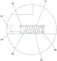
FIG. 1 is a schematic structural view of the present invention;
FIG. 2 is a schematic structural diagram of a right-view cross section of the structural connection of a third supporting plate, two supporting plates, two baffles and the like;
FIG. 3 is an enlarged partial view of FIG. 1 at A according to the present invention;
FIG. 4 is a schematic view of the present invention at a portion B in FIG. 1;
fig. 5 is a partial enlarged structural view at C in fig. 2 according to the present invention.
In the figure: 1. a first support plate; 2. a first connecting plate; 3. a second support plate; 4. rotating the ring; 5. rotating the plate; 6. a pillar; 7. a fixing plate; 8. a first motor; 9. a first rotating shaft; 10. a second connecting plate; 11. a third support plate; 12. a second motor; 13. a first bevel gear; 14. a first male block; 15. a screw; 16. a second bevel gear; 17. a support plate; 18. a second male block; 19. a first compression spring; 20. a first electric cylinder; 21. a buffer block; 22. a baffle plate; 23. a support plate; 24. a rotating plate; 25. a second electric cylinder; 26. a second fixing lug; 27. a third fixing lug; 28. a first splint; 29. an extension spring; 30. a fixed wheel; 31. a fixed block; 32. a first slider; 33. a second compression spring; 34. clamping the column; 35. a second slider; 36. a third compression spring; 37. connecting columns; 38. a second splint; 39. first stationary teeth; 40. a third male block; 41. a fourth compression spring; 42. a third splint; 43. second fixed teeth; 44. mounting a column; 45. a flange; 46. a rib plate; 47. a first fixing lug; 48. an electromagnet; 49. a magnetic block.
Detailed Description
The technical solutions in the embodiments of the present invention will be clearly and completely described below with reference to the drawings in the embodiments of the present invention, and it is obvious that the described embodiments are only a part of the embodiments of the present invention, and not all of the embodiments. All other embodiments, which can be derived by a person skilled in the art from the embodiments given herein without making any creative effort, shall fall within the protection scope of the present invention.
Examples
Referring to fig. 1-5, a large brick clamping device for building a wall comprises a first supporting plate 1, four first connecting plates 2 fixedly connected to the bottom end of the first supporting plate 1, a second supporting plate 3 fixedly connected to the bottom end of the four first connecting plates 2, a rotary slot provided at the bottom end of the second supporting plate 3, a rotary ring 4 rotatably connected to the interior of the rotary slot, a rotary plate 5 fixedly connected to the bottom end of the rotary ring 4, four supporting columns 6 fixedly connected to the bottom end of the first supporting plate 1, a fixing plate 7 fixedly connected to the bottom end of the four supporting columns 6, a first motor 8 fixedly connected to the top end of the fixing plate 7, a first rotary shaft 9 fixedly connected to the output end of the first motor 8, a fixing mechanism provided at the top end of the second supporting plate 3 and extending below the second supporting plate 3 and fixedly connected to the top end of the rotary plate 5, the bottom end of the rotating plate 5 is fixedly connected with four second connecting plates 10, the bottom ends of the four second connecting plates 10 are fixedly connected with a third supporting plate 11, a square groove is arranged at the middle position in the third supporting plate 11, the top end of the third supporting plate 11 is fixedly connected with a second motor 12, an output shaft of the second motor 12 extends into the square groove and is fixedly connected with a first bevel gear 13, the front side and the rear side of the bottom end of the third supporting plate 11 are respectively provided with a first convex groove, the insides of the two first convex grooves are respectively provided with a first convex block 14 in a sliding manner, the insides of the two first convex blocks 14 are respectively in threaded connection with screw rods 15, the front ends and the rear ends of the two screw rods 15 are respectively in rotating connection with the front ends and the rear ends of the two first convex grooves, one ends of the two screw rods 15 close to the square groove are respectively extended into the square groove and are respectively fixedly connected with a second bevel gear 16, the two second bevel gears 16 are respectively meshed with the, the bottom ends of the two first convex blocks 14 are fixedly connected with a support plate 17, the opposite ends of the two support plates 17 are provided with second convex grooves, the interiors of the two second convex grooves are provided with second convex blocks 18 in a sliding manner, the bottom ends of the two second convex blocks 18 are fixedly connected with a first compression spring 19, the top ends of the two second convex grooves are fixedly connected with first electric cylinders 20, the bottom ends of the two first electric cylinders 20 are fixedly connected with buffer blocks 21, the bottom ends of the two buffer blocks 21 are respectively contacted with the top ends of the two second convex blocks 18, the opposite ends of the two second convex blocks 18 are respectively fixedly connected with a baffle 22, the bottom sides of the opposite ends of the two baffle 22 are respectively fixedly connected with a support plate 23, the opposite ends of the two baffle plates 22 are respectively connected with a second clamping plate 38, the bottom end of the second clamping plate 38 is connected with the top end of the support plate 23 in a sliding manner, the left side and the right side of the bottom end of the third support, the inside of two recesses is all rotated and is connected with rotor plate 24, the centre of two rotor plates 24 is rotated through first fixed ear 47 and is connected with the electronic jar 25 of second, the equal fixedly connected with second fixed ear 26 of the bottom side of the one end that two rotor plates 24 are relative, the one end that two rotor plates 24 were kept away from to two fixed ears 26 of second is all rotated and is connected with the fixed ear 27 of third, the equal fixedly connected with first splint 28 of the one end that two fixed ears 26 of second were kept away from to two fixed ears 27 of third, the upside and the downside that two first splint 28 are close to the one end of the fixed ear 27 of third are connected with the top and the bottom of two fixed ears 26 of second through extension spring 29 respectively.
Specifically, fixed establishment includes tight pulley 30 and fixed block 31, the outside at first pivot 9 is established to tight pulley 30 cover, the lateral wall of tight pulley 30 evenly is provided with a plurality of draw-in grooves, the right side fixed connection on the bottom of fixed block 31 and the top of second backup pad 3, the inside of fixed block 31 is provided with first spout, the inside slip of first spout is provided with first slider 32, the right-hand member fixedly connected with second compression spring 33 of first slider 32, the left end fixedly connected with card post 34 of first slider 32, the left end of card post 34 runs through fixed block 31 left wall and extends to the left side of fixed block 31, the left end and the draw-in groove looks adaptation of card post 34, the right-hand member fixedly connected with electro-magnet 48 of first spout, magnetic block 49 is installed to the inside embedding of first slider.
Specifically, the inside of two baffles 22 all is provided with a plurality of second spouts, the inside of a plurality of second spouts all slides and is provided with second slider 35, each second slider 35 is close to the equal fixedly connected with third compression spring 36 of the one end of extension board 17, the one end fixedly connected with that each second slider 35 kept away from third compression spring 36 extends to the spliced pole 37 in the baffle 22 outside, the one end fixedly connected with second splint 38 of second slider 35 is kept away from to a plurality of spliced poles 37, the first fixed tooth 39 of the equal fixedly connected with of one end that two second splint 38 kept away from spliced pole 37, play the effect of buffering through third compression spring 36, avoid the fragment of brick to rock at the in-process of transport, improve through first fixed tooth 39 to the tight steadiness of clamp.
Specifically, the relative one end of two first splint 28 all is provided with the third protruding type groove, the inside in two third protruding type grooves all slides and is provided with third protruding type piece 40, the top and the equal fixedly connected with fourth compression spring 41 in bottom of two third protruding type pieces 40, the one end that first splint 28 was kept away from to two third protruding type pieces 40 all is connected with third splint 42, the equal fixedly connected with of one end that first splint 28 was kept away from to two third splint 42 a plurality of second fixed teeth 43, play the effect of buffering through fourth compression spring 41, avoid the fragment of brick to rock at the in-process of transport, through the fixed tooth 43 improvement of second to the tight steadiness of fragment of brick clamp.
Specifically, the top end of the first supporting plate 1 is fixedly connected with a mounting column 44, and the top end of the mounting column 44 is fixedly connected with a flange 45, so as to be conveniently connected with an external hoisting device.
Specifically, the outer side of the mounting column 44 is fixedly connected with the top end of the first support plate 1 through the rib plate 46, so that the connection stability between the mounting column 44 and the first support plate 1 is improved.
The use method of the large brick clamping device for building walls comprises the following steps:
s1, connecting the lifting device with an external lifting device through a flange 45;
s2, lowering the device, switching on a power supply of the electromagnet 48, attracting the electromagnet 48 and the magnetic block 49 to separate the clamping column 34 from the clamping groove, driving the rotating plate 5 to rotate through the first motor 8, respectively positioning the two third clamping plates 42 at two sides of the brick, then switching off the power supply of the electromagnet 48, clamping the clamping column 34 in the clamping groove through the action of the second compression spring 33 to fix the first rotating shaft 9, rotating the two rotating plates 24 through the second electric cylinder 25, clamping the left side and the right side of the brick through the two third clamping plates 42, and lifting the brick;
s3, two baffle plates 22 are pushed to move downwards through two first electric cylinders 20, two supporting plates 23 are moved to the lower sides of the bricks, then the first bevel gears 13 are driven to rotate through second motors 12, the first bevel gears 13 drive two second bevel gears 16 and two screw rods 15 to rotate, two supporting plates 17 are moved towards the middle, the two supporting plates 23 are moved to the lower sides of the bricks, the two supporting plates 23 are moved upwards through the two first electric cylinders 20, the top ends of the two supporting plates 23 are in contact with the bottom ends of the bricks, and the second motors 12 are continuously operated to enable the two second clamping plates 38 to clamp the front side and the rear side of the bricks;
s4, the bricks are moved to the upper side of the proper position through the hoisting device, the two second clamping plates 38 are moved to two sides through the second motor 12, meanwhile, the baffle plates 22 are pushed to move downwards through the first electric cylinders 20, the two supporting plates 23 are moved to two sides of the bricks, then the first electric cylinders 20 are contracted, the two baffle plates 22 are moved upwards through the action of the first compression springs 19 and moved to the upper side of the bottom end faces of the bricks, then the bricks are placed at the proper position, the two rotating plates 24 are pushed to rotate outwards through the second electric cylinders 25, the third clamping plates 42 are separated from the bricks, and then other bricks are carried.
In this embodiment, the models of the first motor 8, the second motor 12, the first electric cylinder 20 and the second electric cylinder 25 are Y80M1-2, YVF2-63M1-4, GRA-L36 and LX1000-063, respectively, the first motor 8, the second motor 12, the first electric cylinder 20 and the second electric cylinder 25 are all commercially available devices known to those skilled in the art, and we only use them here, and do not improve their structures and functions, and we will not describe here in detail, and the first motor 8, the second motor 12, the first electric cylinder 20 and the second electric cylinder 25 are all provided with control switches matched with them, the installation positions of the control switches are selected according to actual use requirements, so that the operator can conveniently perform operation control, the second motor 12 is a forward/reverse rotation motor, and for forward/reverse rotation of the second motor 12, the forward and reverse rotation of the second electric machine 12 is known to those skilled in the art and is well established and can be realized according to the patent publication CN 109889124A.
To sum up, the large brick clamping device for building a wall and the using method thereof are connected with an external hoisting device through a flange 45 when in use, so that the device descends, meanwhile, a rotating plate 5 is driven to rotate through a first motor 8, two third clamping plates 42 are respectively positioned at two sides of a brick, two rotating plates 24 are driven to rotate through a second electric cylinder 25, the two third clamping plates 42 clamp the brick and lift the brick, two baffle plates 22 are driven to move downwards through two first electric cylinders 20, two supporting plates 23 are moved to the lower side of the brick, then a first bevel gear 13 is driven to rotate through a second motor 12, the first bevel gear 13 drives two second bevel gears 16 and two screw rods 15 to rotate, the two supporting plates 17 move towards the middle, the two supporting plates 23 are moved to the lower side of the brick, the two supporting plates 23 are driven to move upwards through the two first electric cylinders 20, and make the top of two layer boards 23 and the bottom contact of fragment of brick, continue to start second motor 12 and make two second splint 38 press from both sides tightly the fragment of brick, move the fragment of brick to the top of suitable position through hoist device, make two second splint 38 move to both sides through second motor 12, promote baffle 22 through first electronic jar 20 simultaneously and move down, and make two layer boards 23 move to the both sides of fragment of brick, then shrink first electronic jar 20, make two baffle 22 move up through the effect of first compression spring 19, and move to the upside of fragment of brick bottom face, then place the fragment of brick in suitable position, promote two rotor plates 24 through second electronic jar 25 and rotate to the outside, third splint 42 and fragment of brick separate, then carry other fragments of brick.
Although embodiments of the present invention have been shown and described, it will be appreciated by those skilled in the art that changes, modifications, substitutions and alterations can be made in these embodiments without departing from the principles and spirit of the invention, the scope of which is defined in the appended claims and their equivalents.
Claims (7)
1. The utility model provides a building is built a wall and is used large-scale fragment of brick clamping device, includes first backup pad (1), its characterized in that, four first connecting plate (2) of bottom fixedly connected with of first backup pad (1), four bottom fixedly connected with second backup pad (3) of first connecting plate (2), the bottom of second backup pad (3) is provided with the turn trough, the inside of turn trough is rotated and is connected with swivel (4), swivel (4) bottom fixedly connected with commentaries on classics board (5), four pillar (6) of bottom fixedly connected with of first backup pad (1), four the bottom fixedly connected with fixed plate (7) of pillar (6), the first motor (8) of top fixedly connected with of fixed plate (7), the first pivot (9) of output fixedly connected with of first motor (8), the bottom of first pivot (9) run through and extend to the below of second backup pad (3) and with the top of commentaries on classics board (5) Fixedly connected, the top end of the second supporting plate (3) is positioned at the outer side of the first rotating shaft (9) and is provided with a fixing mechanism, the bottom end of the rotating plate (5) is fixedly connected with four second connecting plates (10), the bottom end of the four second connecting plates (10) is fixedly connected with a third supporting plate (11), a square groove is arranged at the middle position of the inner part of the third supporting plate (11), the top end of the third supporting plate (11) is fixedly connected with a second motor (12), an output shaft of the second motor (12) extends to the inner part of the square groove and is fixedly connected with a first bevel gear (13), the front side and the rear side of the bottom end of the third supporting plate (11) are both provided with first convex grooves, the inner parts of the two first convex grooves are both slidably provided with first convex blocks (14), and the inner parts of the two first convex blocks (14) are both in threaded connection with a screw rod (15), the front ends and the rear ends of the two screw rods (15) are respectively rotatably connected with the front ends and the rear ends of the two first convex grooves, one ends of the two screw rods (15) close to the square grooves are respectively extended into the square grooves and are respectively and fixedly connected with second conical gears (16), the two second conical gears (16) are respectively meshed with the first conical gears (13), the bottom ends of the two first convex blocks (14) are respectively and fixedly connected with a support plate (17), the opposite ends of the two support plates (17) are respectively provided with a second convex groove, the inner parts of the two second convex grooves are respectively and slidably provided with second convex blocks (18), the bottom ends of the two second convex blocks (18) are respectively and fixedly connected with a first compression spring (19), the top ends of the two second convex grooves are respectively and fixedly connected with a first electric cylinder (20), and the bottom ends of the two first electric cylinders (20) are respectively and fixedly connected with a buffer block (21), the bottom ends of the two buffer blocks (21) are respectively contacted with the top ends of the two second convex blocks (18), the opposite ends of the two second convex blocks (18) are fixedly connected with baffle plates (22), the bottom sides of the opposite ends of the two baffle plates (22) are fixedly connected with supporting plates (23), the opposite ends of the two baffle plates (22) are respectively connected with second clamping plates (38), the bottom ends of the second clamping plates (38) are slidably connected with the top ends of the supporting plates (23), the left side and the right side of the bottom end of the third supporting plate (11) are respectively provided with a groove, the inner parts of the two grooves are respectively and rotatably connected with rotating plates (24), the middle parts of the two rotating plates (24) are rotatably connected with second electric cylinders (25) through first fixing lugs (47), and the bottom sides of the opposite ends of the two rotating plates (24) are respectively and fixedly connected with second fixing lugs (26), two the fixed ear of second (26) is kept away from the one end of two rotating plates (24) and is all rotated and be connected with the fixed ear of third (27), two the fixed ear of third (27) is kept away from the equal fixedly connected with first splint of one end (28) of two fixed ears of second (26), two upside and the downside of the one end that first splint (28) are close to the fixed ear of third (27) are connected with the top and the bottom of two fixed ears of second (26) through extension spring (29) respectively.
2. The large brick clamping device for building a wall according to claim 1, wherein the fixing mechanism comprises a fixing wheel (30) and a fixing block (31), the fixing wheel (30) is sleeved outside the first rotating shaft (9), a plurality of clamping grooves are uniformly formed in the outer side wall of the fixing wheel (30), the bottom end of the fixing block (31) is fixedly connected with the right side of the top end of the second supporting plate (3), a first sliding groove is formed in the fixing block (31), a first sliding block (32) is arranged in the first sliding groove in a sliding manner, a second compression spring (33) is fixedly connected with the right end of the first sliding block (32), a clamping column (34) is fixedly connected with the left end of the first sliding block (32), the left end of the clamping column (34) penetrates through the left wall of the fixing block (31) and extends to the left side of the fixing block (31), and the left end of the clamping column (34) is matched with the clamping grooves, the right end of the first sliding groove is fixedly connected with an electromagnet (48), and a magnetic block (49) is embedded in the first sliding block.
3. The large brick clamping device for building walls according to claim 2, wherein a plurality of second sliding grooves are formed in each of the two baffles (22), a second sliding block (35) is slidably arranged in each of the plurality of second sliding grooves, a third compression spring (36) is fixedly connected to one end, close to the support plate (17), of each second sliding block (35), a connecting column (37) extending to the outer side of the baffle (22) is fixedly connected to one end, far away from the third compression spring (36), of each second sliding block (35), a second clamping plate (38) is fixedly connected to one end, far away from the second sliding block (35), of each connecting column (37), and a first fixing tooth (39) is fixedly connected to one end, far away from the connecting column (37), of each second clamping plate (38).
4. The large brick clamping device for building walls according to claim 3, wherein one end of each of the two first clamping plates (28) opposite to each other is provided with a third convex groove, a third convex block (40) is slidably arranged inside each of the two third convex grooves, the top end and the bottom end of each of the two third convex blocks (40) are fixedly connected with a fourth compression spring (41), one end of each of the two third convex blocks (40) far away from the first clamping plate (28) is connected with a third clamping plate (42), and one end of each of the two third clamping plates (42) far away from the first clamping plate (28) is fixedly connected with a plurality of second fixed teeth (43).
5. The large brick clamping device for building a wall according to claim 4, wherein a mounting column (44) is fixedly connected to the top end of the first supporting plate (1), and a flange (45) is fixedly connected to the top end of the mounting column (44).
6. The large brick clamping device for building walls according to claim 5, wherein the outer side of the mounting column (44) is fixedly connected with the top end of the first supporting plate (1) through a rib plate (46).
7. A large-sized brick clamping device for building wall and a using method thereof, wherein the using method of the large-sized brick clamping device for building wall according to any one of claims 1 to 6 is used, and comprises the following steps:
s1, connecting the lifting device with an external lifting device through a flange (45);
s2, lowering the device, switching on a power supply of an electromagnet (48), attracting the electromagnet (48) and a magnetic block (49) to separate a clamping column (34) from a clamping groove, driving a rotating plate (5) to rotate through a first motor (8), respectively positioning two third clamping plates (42) at two sides of a brick, switching off the power supply of the electromagnet (48), clamping the clamping column (34) in the clamping groove to fix a first rotating shaft (9) through the action of a second compression spring (33), rotating the two rotating plates (24) through a second electric cylinder (25), clamping the left side and the right side of the brick through the two third clamping plates (42), and lifting the brick;
s3, two baffles (22) are pushed to move downwards through two first electric cylinders (20), two supporting plates (23) are moved to the lower sides of bricks, then a first bevel gear (13) is driven to rotate through a second motor (12), the first bevel gear (13) drives two second bevel gears (16) and two screws (15) to rotate, two supporting plates (17) are moved towards the middle, the two supporting plates (23) are moved to the lower sides of the bricks, the two supporting plates (23) are moved upwards through the two first electric cylinders (20), the top ends of the two supporting plates (23) are in contact with the bottom ends of the bricks, and the second motor (12) is continuously operated to enable two second clamping plates (38) to clamp the front side and the rear side of the bricks;
s4, the bricks are moved to the upper side of the proper position through the hoisting device, the two second clamping plates (38) are moved to two sides through the second motor (12), meanwhile, the baffle plates (22) are pushed to move downwards through the first electric cylinders (20), the two supporting plates (23) are moved to two sides of the bricks, then the first electric cylinders (20) are contracted, the two baffle plates (22) are moved upwards through the action of the first compression springs (19) and moved to the upper sides of the bricks, then the bricks are placed at the proper position, the two rotating plates (24) are pushed to rotate outwards through the second electric cylinders (25), the third clamping plates (42) are separated from the bricks, and then other bricks are carried.
Priority Applications (1)
| Application Number | Priority Date | Filing Date | Title |
|---|---|---|---|
| CN202110195611.6A CN112942855B (en) | 2021-02-22 | 2021-02-22 | Large brick block clamping device for building wall construction and use method thereof |
Applications Claiming Priority (1)
| Application Number | Priority Date | Filing Date | Title |
|---|---|---|---|
| CN202110195611.6A CN112942855B (en) | 2021-02-22 | 2021-02-22 | Large brick block clamping device for building wall construction and use method thereof |
Publications (2)
| Publication Number | Publication Date |
|---|---|
| CN112942855A true CN112942855A (en) | 2021-06-11 |
| CN112942855B CN112942855B (en) | 2023-05-12 |
Family
ID=76245107
Family Applications (1)
| Application Number | Title | Priority Date | Filing Date |
|---|---|---|---|
| CN202110195611.6A Active CN112942855B (en) | 2021-02-22 | 2021-02-22 | Large brick block clamping device for building wall construction and use method thereof |
Country Status (1)
| Country | Link |
|---|---|
| CN (1) | CN112942855B (en) |
Cited By (6)
| Publication number | Priority date | Publication date | Assignee | Title |
|---|---|---|---|---|
| CN113356335A (en) * | 2021-06-30 | 2021-09-07 | 兰顺祥 | Municipal administration is laid with shaft step and is put |
| CN114393364A (en) * | 2022-02-18 | 2022-04-26 | 中铁建港航局集团勘察设计院有限公司 | Double-manipulator conveying device of automatic welding machine |
| CN114476484A (en) * | 2022-02-14 | 2022-05-13 | 李晓练 | Building brick based clamping device |
| CN114753662A (en) * | 2022-03-22 | 2022-07-15 | 北京锦尚盈华装饰设计有限公司 | Manipulator of wall building robot |
| CN115351582A (en) * | 2022-10-20 | 2022-11-18 | 江苏威泽智能科技股份有限公司 | Feed bin for feeding of numerical control machine tool |
| CN116852407A (en) * | 2023-08-29 | 2023-10-10 | 深圳市汇利德邦环保科技有限公司 | Brick clamping tool |
Citations (6)
| Publication number | Priority date | Publication date | Assignee | Title |
|---|---|---|---|---|
| CN101956462A (en) * | 2010-09-07 | 2011-01-26 | 王恒 | Walling machine |
| CN105347171A (en) * | 2015-11-27 | 2016-02-24 | 瑞安市瑞港机械有限公司 | Large-sized building block lifting appliance |
| WO2016166541A1 (en) * | 2015-04-16 | 2016-10-20 | Klawz Limited | Scaffold clamps |
| CN206782622U (en) * | 2017-03-01 | 2017-12-22 | 衢州市联橙环保科技有限公司 | One kind building brick clamp |
| CN110316652A (en) * | 2019-05-10 | 2019-10-11 | 郑州铁路职业技术学院 | A kind of railway freight hanging device |
| CN112046750A (en) * | 2020-10-12 | 2020-12-08 | 杨相兵 | Meal delivery device based on unmanned aerial vehicle |
-
2021
- 2021-02-22 CN CN202110195611.6A patent/CN112942855B/en active Active
Patent Citations (6)
| Publication number | Priority date | Publication date | Assignee | Title |
|---|---|---|---|---|
| CN101956462A (en) * | 2010-09-07 | 2011-01-26 | 王恒 | Walling machine |
| WO2016166541A1 (en) * | 2015-04-16 | 2016-10-20 | Klawz Limited | Scaffold clamps |
| CN105347171A (en) * | 2015-11-27 | 2016-02-24 | 瑞安市瑞港机械有限公司 | Large-sized building block lifting appliance |
| CN206782622U (en) * | 2017-03-01 | 2017-12-22 | 衢州市联橙环保科技有限公司 | One kind building brick clamp |
| CN110316652A (en) * | 2019-05-10 | 2019-10-11 | 郑州铁路职业技术学院 | A kind of railway freight hanging device |
| CN112046750A (en) * | 2020-10-12 | 2020-12-08 | 杨相兵 | Meal delivery device based on unmanned aerial vehicle |
Cited By (8)
| Publication number | Priority date | Publication date | Assignee | Title |
|---|---|---|---|---|
| CN113356335A (en) * | 2021-06-30 | 2021-09-07 | 兰顺祥 | Municipal administration is laid with shaft step and is put |
| CN114476484A (en) * | 2022-02-14 | 2022-05-13 | 李晓练 | Building brick based clamping device |
| CN114476484B (en) * | 2022-02-14 | 2024-03-05 | 何祖俊 | Based on building fragment of brick clamping device |
| CN114393364A (en) * | 2022-02-18 | 2022-04-26 | 中铁建港航局集团勘察设计院有限公司 | Double-manipulator conveying device of automatic welding machine |
| CN114753662A (en) * | 2022-03-22 | 2022-07-15 | 北京锦尚盈华装饰设计有限公司 | Manipulator of wall building robot |
| CN115351582A (en) * | 2022-10-20 | 2022-11-18 | 江苏威泽智能科技股份有限公司 | Feed bin for feeding of numerical control machine tool |
| CN116852407A (en) * | 2023-08-29 | 2023-10-10 | 深圳市汇利德邦环保科技有限公司 | Brick clamping tool |
| CN116852407B (en) * | 2023-08-29 | 2023-11-14 | 深圳市汇利德邦环保科技有限公司 | Brick clamping tool |
Also Published As
| Publication number | Publication date |
|---|---|
| CN112942855B (en) | 2023-05-12 |
Similar Documents
| Publication | Publication Date | Title |
|---|---|---|
| CN112942855A (en) | Large brick clamping device for building wall and using method thereof | |
| CN112854815B (en) | Building wall is with demolising controlling means | |
| CN207877147U (en) | A kind of clamp device for building | |
| CN110125862B (en) | Auxiliary device is used in installation of way flag lamp pole | |
| CN216881782U (en) | Die hole groove machining device | |
| CN110947554A (en) | Automatic clamping and spraying equipment for surface of cylinder | |
| CN103086161B (en) | Rotatory brick device of grabbing of hacking machine | |
| CN211871239U (en) | Automatic feeding device for machining | |
| CN220033777U (en) | Hoisting equipment for prefabricated parts of building engineering | |
| CN210972948U (en) | Novel automatic carrying device | |
| CN216836909U (en) | Municipal pipeline laying device with distance adjusting function | |
| CN206395382U (en) | A kind of new type formwork material pusher | |
| CN212798480U (en) | Turning device in aerated concrete block transmission process | |
| CN215750105U (en) | Clamping device for ceramic tile cutting | |
| CN214163566U (en) | Ceramic tile cutting device for architectural decoration engineering | |
| CN214082182U (en) | Portable cutting ceramic tile device | |
| CN213946835U (en) | Vibration forming machine for refractory brick production | |
| CN210702418U (en) | High temperature resistant steel casting automatic pouring equipment | |
| CN211074096U (en) | Possesses form removal machine of automatic form removal | |
| CN209937775U (en) | Tire forming clamp | |
| CN208584313U (en) | Burr remover is used in a kind of production of gasket | |
| CN218019222U (en) | Concrete block production is with evaporating cauldron | |
| CN213265434U (en) | Electric power overhauls uses hoisting accessory | |
| CN218703393U (en) | Conveying mechanism | |
| CN217626310U (en) | Plate conveying machine for producing perforated bricks |
Legal Events
| Date | Code | Title | Description |
|---|---|---|---|
| PB01 | Publication | ||
| PB01 | Publication | ||
| SE01 | Entry into force of request for substantive examination | ||
| SE01 | Entry into force of request for substantive examination | ||
| TA01 | Transfer of patent application right | ||
| TA01 | Transfer of patent application right |
Effective date of registration: 20230425 Address after: 831100 8th floor, Qingnian Shangdu, Qingnian South Road, Changji City, Changji Hui Autonomous Prefecture, Xinjiang Uygur Autonomous Region Applicant after: Xinjiang Boji Construction Engineering Co.,Ltd. Address before: 510000 Nanqiao building, 342 Shengtai Road, Shiqiao street, Panyu District, Guangzhou City, Guangdong Province Applicant before: Qin Chao |
|
| GR01 | Patent grant | ||
| GR01 | Patent grant |