CN112921633B - Cutting device is used in non-woven fabrics production and processing - Google Patents
Cutting device is used in non-woven fabrics production and processing Download PDFInfo
- Publication number
- CN112921633B CN112921633B CN202110111537.5A CN202110111537A CN112921633B CN 112921633 B CN112921633 B CN 112921633B CN 202110111537 A CN202110111537 A CN 202110111537A CN 112921633 B CN112921633 B CN 112921633B
- Authority
- CN
- China
- Prior art keywords
- sliding
- fixedly connected
- workbench
- motor
- fixing
- Prior art date
- Legal status (The legal status is an assumption and is not a legal conclusion. Google has not performed a legal analysis and makes no representation as to the accuracy of the status listed.)
- Active
Links
Images


Classifications
-
- D—TEXTILES; PAPER
- D06—TREATMENT OF TEXTILES OR THE LIKE; LAUNDERING; FLEXIBLE MATERIALS NOT OTHERWISE PROVIDED FOR
- D06H—MARKING, INSPECTING, SEAMING OR SEVERING TEXTILE MATERIALS
- D06H7/00—Apparatus or processes for cutting, or otherwise severing, specially adapted for the cutting, or otherwise severing, of textile materials
-
- D—TEXTILES; PAPER
- D06—TREATMENT OF TEXTILES OR THE LIKE; LAUNDERING; FLEXIBLE MATERIALS NOT OTHERWISE PROVIDED FOR
- D06C—FINISHING, DRESSING, TENTERING OR STRETCHING TEXTILE FABRICS
- D06C15/00—Calendering, pressing, ironing, glossing or glazing textile fabrics
- D06C15/04—Calendering, pressing, ironing, glossing or glazing textile fabrics between rollers and co-operating concave surfaces
Landscapes
- Engineering & Computer Science (AREA)
- Textile Engineering (AREA)
- Treatment Of Fiber Materials (AREA)
Abstract
The invention provides a cutting device for non-woven fabric production and processing, which comprises a workbench, wherein two side edges of the top end of the workbench are fixedly connected with fixed plates, four corners of the bottom end of the workbench are provided with damping wheel mechanisms, two sides of the bottom end of the workbench are fixedly connected with fixing mechanisms, the middle of the top of the workbench is provided with a groove, two sides of the top of the workbench are provided with first sliding chutes, the first sliding chutes are connected with two sliding plates in a sliding manner, the tops of the two sliding plates are provided with second sliding chutes, the second sliding chutes are connected with two clamping mechanisms in a sliding manner, flattening mechanisms are arranged in the groove, tooth grooves are formed in the two sides of the workbench and in positions corresponding to the two ends of the flattening mechanisms, and a sliding mechanism is arranged between the two fixed plates: the position of clamping structure can be adjusted according to the size of non-woven fabrics to can adjust the position of tool bit as required multidirectionally, can flatten the processing after cutting, improve the production quality of non-woven fabrics.
Description
Technical Field
The invention relates to the technical field of non-woven fabric production and processing, in particular to a cutting device for non-woven fabric production and processing.
Background
Nonwoven fabrics, also known as non-woven fabrics, needle punched cotton, and the like, are composed of oriented or random fibers. The non-woven fabric is called as cloth because of having the appearance and certain properties of the cloth, and has the characteristics of moisture resistance, ventilation, flexibility, light weight, no combustion supporting, easy decomposition, no toxicity or irritation, rich color, low price, recycling and the like. In the process of producing and processing the non-woven fabric, a large piece of cloth needs to be cut for use, however, the existing cutting device for producing and processing the non-woven fabric has the following defects:
1) The mechanism that presss from both sides tight non-woven fabrics among cutting device is all for fixed mechanism for the non-woven fabrics production and processing, has brought the inconvenience when the position that needs to cut is adjusted to can only cut the non-woven fabrics of fixed size, use comparatively to limit.
2) The cutting device for the production and processing of the existing non-woven fabrics can move and cut only in one way in the cutting process, or can not meet the cutting requirements of different positions in the cutting process due to the fixed cutting mode of the cutter head.
3) When the non-woven fabric cutting device cuts, the non-woven fabric is often wrinkled, the phenomenon of unevenness occurs, and the production quality of the non-woven fabric is influenced.
Disclosure of Invention
The invention aims to provide a cutting device for non-woven fabric production and processing, and aims to solve the problems that a clamping structure is fixed, a cutting tool bit can only be adjusted in a single-item moving mode or the non-woven fabric cannot be wrinkled in the prior art.
In order to achieve the purpose, the invention provides the following technical scheme: the utility model provides a cutting device is used in non-woven fabrics production and processing, includes the workstation, the equal fixedly connected with fixed plate in top both sides side of workstation, two common fixedly connected with mounting panel between the top of fixed plate, the bottom four corners of workstation all is equipped with damping wheel mechanism, the equal fixedly connected with fixed establishment in bottom both sides of workstation, set up flutedly in the middle of the top of workstation, first spout has been seted up to the top both sides of workstation, sliding connection has two sliding plates, two on the first spout the second spout has all been seted up to the top of sliding plate, sliding connection has two clamping mechanism on the second spout, the inside of recess is equipped with flattening mechanism, the tooth's socket has been seted up to the both sides of workstation and the corresponding position in both ends with flattening mechanism, two be equipped with slide mechanism between the fixed plate, slide mechanism is last sliding connection has cutting mechanism, one of them opposite side fixedly connected with controller of fixed plate.
In order to facilitate stable movement of the device, as a preferred aspect of the present invention: damping wheel mechanism includes sleeve, sliding block, the first spring of a plurality of and universal wheel, the bottom fixed connection of telescopic top and workstation, telescopic inside sliding connection has the sliding block, the top elastic connection of sliding block has the first spring of a plurality of, a plurality of the top of first spring all with telescopic inside roof elastic connection, the bottom of sliding block is rotated with the top of universal wheel and is connected.
In order to facilitate the fixing device not to slide, as a preferred scheme of the invention: the fixing mechanism comprises a fixing groove, a hydraulic cylinder and a sucker, the top end of the fixing groove is fixedly connected with the bottom end of the workbench, the inner top wall of the fixing groove is fixedly connected with the top end of the hydraulic cylinder, and the bottom end of the hydraulic cylinder is fixedly connected with the top end of the sucker.
In order to facilitate the clamping of the nonwoven, as a preferred embodiment of the invention: the clamping mechanism comprises a first sliding block, a U-shaped plate, a second spring, a screw rod and a pressing plate, the first sliding block is connected with the sliding plate in a sliding mode through a second sliding groove, the top of the first sliding block is fixedly connected with the U-shaped plate, the screw rod penetrates through the top of the U-shaped plate and is fixedly connected with the pressing plate, the screw rod is in threaded connection with the U-shaped plate, the top end of the pressing plate is elastically connected with the second spring, and the top end of the second spring is abutted to the inner top wall of the U-shaped plate.
In order to flatten the cut nonwoven, as a preferred embodiment of the present invention: the mechanism that flattens includes compression roller, pivot, gear and crank, the rotation is connected with the pivot in the middle of the inside of compression roller, the both ends fixedly connected with gear of pivot, the one end fixedly connected with crank of gear, the gear is connected with the tooth's socket meshing.
In order to facilitate the sliding of the cutting mechanism, as a preferable aspect of the present invention: slide mechanism includes first motor, two first lead screws, drive wheel, follows driving wheel, two second sliders and belt, two be equipped with two first lead screws, two between the fixed plate sliding connection has the second slider on the first lead screw, one side fixed connection of bearing and fixed plate is all passed through to the one end of first lead screw, one of them the lateral wall that the other end of first lead screw passed the fixed plate rotates and is connected with first motor, on the first lead screw and the one side that is located first motor rotate and be connected with the drive wheel, another the lateral wall that the other end of first lead screw passed the fixed plate rotates and is connected with from the driving wheel, the drive wheel with rotate jointly between the follow driving wheel and be connected with the belt.
In order to make the device achieve the purpose of cutting, the invention adopts a preferable scheme that: the utility model discloses a cutting mechanism, including first motor, first slider, second slider, connecting plate, fixing base, cutter disc, first slider, electric telescopic handle, connecting plate, fixing base, cutter disc, the both ends of guide bar respectively with two first slider fixed connection, the one end of first slider rotates with one of them second slider to be connected, the other end of first slider passes another first slider and rotates and be connected with the first motor, common sliding connection has the first slider on first slider and the guide bar, the bottom both sides fixedly connected with electric telescopic handle of first slider, electric telescopic handle's bottom fixedly connected with connecting plate, the bottom fixedly connected with fixing base of connecting plate, the inside of fixing base is rotated and is connected with the cutter disc, one side of cutter disc is rotated through the axle and is connected with the first motor.
In order to facilitate the normal operation of the press roll, as a preferred scheme of the invention: the depth of the groove is greater than the height of the compression roller.
In order to make the model of the controller known, as a preferred solution of the present invention: the controller is in the model of MAM-200.
In order to make the device work normally, as a preferred scheme of the invention: the first motor, the second motor, the third motor, the hydraulic cylinder and the electric telescopic rod are all electrically connected with an external power supply through the controller.
Compared with the prior art, the cutting device for producing and processing the non-woven fabric, provided by the invention, has the following beneficial effects:
1) The clamping mechanism is provided with a screw rod and a first sliding groove which are matched with each other, the second sliding groove is matched with the sliding plate, the sliding plate slides in the first sliding groove according to the length of the clamped non-woven fabric, the clamping length can be adjusted, the clamping mechanism is adjusted to slide in the second sliding groove on the sliding plate according to the width of the clamped non-woven fabric, so that the non-woven fabric is adjusted to be in a proper width, the non-woven fabric is clamped through the screw rod in the clamping mechanism, the non-woven fabric can be effectively adjusted according to the size of the non-woven fabric and the size of a part needing to be cut, the limitation cannot be caused during use, the flexibility is high, and the utilization rate is increased;
2) Through the mutual matching of the second sliding block in the sliding mechanism, the third sliding block in the cutting mechanism and the electric telescopic rod, the position of the cutter head on the horizontal plane can be adjusted through the sliding of the second sliding block and the sliding of the third sliding block, and the cutter head can move and be adjusted in the vertical direction through the electric telescopic rod, so that the cutter head can be adjusted to any position, the use flexibility is high, and the utilization effect of the device is improved;
3) Through rolling of the compression roller in the flattening mechanism that is equipped with for the non-woven fabrics utilizes the compression roller to flatten after cutting, and easy operation has improved the production quality of non-woven fabrics.
Drawings
The accompanying drawings, which are included to provide a further understanding of the invention and are incorporated in and constitute a part of this specification, illustrate embodiments of the invention and together with the description serve to explain the principles of the invention and not to limit the invention. In the drawings:
FIG. 1 is a schematic view of the overall structure proposed by the present invention;
FIG. 2 is a schematic front view of the structure of the present invention;
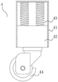
FIG. 3 is a schematic structural diagram of a damping wheel mechanism according to the present invention;
FIG. 4 is a schematic structural diagram of a fixing mechanism according to the present invention;
FIG. 5 is a schematic structural diagram of a clamping mechanism according to the present invention;
FIG. 6 is a schematic structural diagram of a pressing mechanism according to the present invention;
FIG. 7 is a schematic structural diagram of a sliding mechanism according to the present invention;
fig. 8 is a schematic structural view of a cutting mechanism according to the present invention.
In the figure: 1. a work table; 2. a fixing plate; 3. mounting a plate; 4. a damping wheel mechanism; 41. a sleeve; 42. a slider; 43. a first spring; 44. a universal wheel; 5. a fixing mechanism; 51. a fixing groove; 52. a hydraulic cylinder; 53. a suction cup; 6. a groove; 7. a first chute; 8. a sliding plate; 9. a second chute; 10. a clamping mechanism; 101. a first slider; 102. a U-shaped plate; 103. a second spring; 104. a screw; 105. pressing a plate; 11. a flattening mechanism; 111. pressing rollers; 112. a rotating shaft; 113. a gear; 114. a crank; 12. a tooth socket; 13. a sliding mechanism; 131. a first motor; 132. a first lead screw; 133. a drive wheel; 134. a driven wheel; 135. a second slider; 136. a belt; 14. a cutting mechanism; 141. a second motor; 142. a third motor; 143. a second lead screw; 144. a guide bar; 145. a third slider; 146. an electric telescopic rod; 147. a connecting plate; 148. a fixed seat; 149. a cutter head; 15. and a controller.
Detailed Description
The technical solutions in the embodiments of the present invention will be clearly and completely described below with reference to the drawings in the embodiments of the present invention, and it is obvious that the described embodiments are only a part of the embodiments of the present invention, and not all of the embodiments. All other embodiments, which can be derived by a person skilled in the art from the embodiments given herein without making any creative effort, shall fall within the protection scope of the present invention.
Example 1
Referring to fig. 1-8, the present invention provides the following technical solutions: the utility model provides a cutting device is used in non-woven fabrics production and processing, including workstation 1, the equal fixedly connected with fixed plate 2 of the top both sides side of workstation 1, common fixedly connected with mounting panel 3 between the top of two fixed plate 2, the bottom four corners of workstation 1 all is equipped with damper 4, the equal fixedly connected with fixed establishment 5 in the bottom both sides of workstation 1, set up fluted 6 in the middle of the top of workstation 1, first spout 7 has been seted up to the top both sides of workstation 1, sliding connection has two sliding plates 8 on first spout 7, second spout 9 has all been seted up at the top of two sliding plates 8, sliding connection has two clamping mechanism 10 on second spout 9, the inside of recess 6 is equipped with flattening mechanism 11, tooth's socket 12 has been seted up to the both sides of workstation 1 and the position corresponding with flattening mechanism 11's both ends, be equipped with slide mechanism 13 between two fixed plate 2, sliding connection has cutting mechanism 14 on slide mechanism 13, the opposite side fixedly connected with controller 15 of one of fixed plate 2.
In this embodiment: damping wheel mechanism 4 includes sleeve 41, sliding block 42, the first spring 43 of a plurality of and universal wheel 44, the top of sleeve 41 and the bottom fixed connection of workstation 1, and the inside sliding connection of sleeve 41 has sliding block 42, and the top elastic connection of sliding block 42 has the first spring 43 of a plurality of, and the top of the first spring 43 of a plurality of all is connected with the inside roof elastic connection of sleeve 41, and the bottom of sliding block 42 rotates with the top of universal wheel 44 to be connected.
Specifically, when the device needs to be moved, the damping wheel mechanism 4 moves, the sliding block 42 moves up and down in the sleeve 41 in the moving process, and the first spring 43 buffers and damps the vibration, so that the vibration of the device is reduced in the moving process, the stability of the device is improved, and the damage to the device caused by the vibration is avoided.
In this embodiment: the fixing mechanism 5 comprises a fixing groove 51, a hydraulic cylinder 52 and a suction cup 53, wherein the top end of the fixing groove 51 is fixedly connected with the bottom end of the workbench 1, the inner top wall of the fixing groove 51 is fixedly connected with the top end of the hydraulic cylinder 52, and the bottom end of the hydraulic cylinder 52 is fixedly connected with the top end of the suction cup 53.
Specifically, after the device is put steadily, fix the device through fixed establishment 5, avoid taking place to slide, carry out the downstream through pneumatic cylinder 52 in controller 15 control fixed slot 51, until the sucking disc 53 butt of pneumatic cylinder 52 bottom to ground, through the butt and the absorption of sucking disc 53 and ground for the difficult emergence of device slides, has increased the stability of device.
In this embodiment: clamping mechanism 10 includes first slider 101, U type board 102, second spring 103, screw rod 104 and clamp plate 105, first slider 101 passes through second spout 9 and sliding plate 8 sliding connection, the top fixedly connected with U type board 102 of first slider 101, screw rod 104 passes the top of U type board 102 and fixedly connected with clamp plate 105, screw rod 104 and U type board 102 threaded connection, the top elastic connection of clamp plate 105 has second spring 103, the top of second spring 103 and the inside top wall butt of U type board 102.
Specifically, before cutting the non-woven fabrics, it is fixed to need carry out the centre gripping to the non-woven fabrics, makes the non-woven fabrics firmly fixed through clamping mechanism 10, and rotating screw 104 to the top is placed the non-woven fabrics on U template 102 to rotating screw 104 once more makes clamp plate 105 under the screw 104 push down the non-woven fabrics, and makes through second spring 103 and support clamp plate 105 tightly, thereby presss from both sides the non-woven fabrics tightly.
In this embodiment: the flattening mechanism 11 comprises a pressing roller 111, a rotating shaft 112, a gear 113 and a crank 114, the rotating shaft 112 is rotatably connected in the middle of the interior of the pressing roller 111, the gears 113 are fixedly connected to two ends of the rotating shaft 112, the crank 114 is fixedly connected to one end of the gear 113, and the gear 113 is meshed with the tooth grooves 12.
Specifically, need flatten the non-woven fabrics after the non-woven fabrics has cut, make gear 113 meshing rotation in tooth's socket 12 through the crank 114 that rotates among the flattening mechanism 11 to drive pivot 112 and compression roller 111 and rotate, compression roller 111 rolls the non-woven fabrics, makes the non-woven fabrics become more level and more smooth, has improved the quality of non-woven fabrics.
In this embodiment: the sliding mechanism 13 includes a first motor 131, two first lead screws 132, a driving wheel 133, a driven wheel 134, two second sliders 135 and a belt 136, two first lead screws 132 are disposed between the two fixing plates 2, the two first lead screws 132 are connected with the second sliders 135 in a sliding manner, one end of each first lead screw 132 is fixedly connected with one side of each fixing plate 2 through a bearing, the other end of one first lead screw 132 penetrates through the side wall of each fixing plate 2 and is connected with the first motor 131 in a rotating manner, one side of each first lead screw 132, which is located on the first motor 131, is connected with the driving wheel 133 in a rotating manner, the other end of the other first lead screw 132 penetrates through the side wall of each fixing plate 2 and is connected with the driven wheel 134 in a rotating manner, and the belt 136 is connected between the driving wheel 133 and the driven wheel 134 in a rotating manner.
Specifically, when the cutting mechanism 14 needs to be moved and adjusted to a proper position, the cutting mechanism 14 slides through the sliding mechanism 13, the first motor 131 is controlled to rotate through the controller 15, so that the first motor 131 drives the first lead screw 132 to rotate, the driving wheel 133 on one of the first lead screws 132 drives the driven wheel 134 to rotate through the belt 136, the driven wheel 134 drives the first lead screw 132 to rotate, the first lead screw 132 drives the second slider 135 to move on the first lead screw 132, and the cutting mechanism 14 is driven to move until the cutting mechanism moves to a proper position.
In this embodiment: the cutting mechanism 14 comprises a second motor 141, a third motor 142, second screw rods 143, a guide rod 144, third sliders 145, electric telescopic rods 146, a connecting plate 147, a fixed seat 148 and a cutter disc 149, two ends of the guide rod 144 are fixedly connected with the two second slider 135 respectively, one end of each second screw rod 143 is rotatably connected with one of the second slider 135, the other end of each second screw rod 143 penetrates through the other second slider 135 and is rotatably connected with the second motor 141, the second screw rods 143 and the guide rods 144 are jointly and slidably connected with the third slider 145, two sides of the bottom end of each third slider 145 are fixedly connected with the electric telescopic rods 146, the connecting plate 147 is fixedly connected with the bottom of each connecting plate 147, the cutter disc 149 is rotatably connected to the inside of each fixed seat 148, and the third motor 142 is rotatably connected to one side of each cutter disc 149 through a shaft.
Specifically, when the non-woven fabric is cut, the cutting mechanism 14 cuts the non-woven fabric, the controller 15 controls the second motor 141 to rotate, the second motor 141 drives the second lead screw 143 to rotate, the third sliding block 145 on the second lead screw 143 slides on the second lead screw 143 and the guide rod 144 until the non-woven fabric moves to a proper position, the controller 15 controls the electric telescopic rod 146 to work, the electric telescopic rod 146 moves downwards to a proper cutting position, the controller 15 controls the third motor 142 to rotate, the third motor 142 drives the cutter disc 149 to rotate, and therefore the cutter disc 149 cuts the non-woven fabric, and the third sliding block 145 moves, so that the cutter disc 149 cuts the non-woven fabric back and forth.
In this embodiment: the depth of the groove 6 is greater than the height of the pressure roller 111.
Specifically, when the pressing roll 111 flattens, the non-woven fabric is rolled in the groove 6 by the pressing roll 111, so that the non-woven fabric is flattened, and if the depth of the groove 6 is smaller than the height of the pressing roll 111, the upper cutting mechanism 14 is inconvenient to cut.
In this embodiment: the controller 15 is of the type MAM-200.
Specifically, the controller 15 of the type MAM-200 makes the device simple and convenient to operate.
In this embodiment: the first motor 131, the second motor 141, the third motor 142, the hydraulic cylinder 52 and the electric telescopic rod 146 are electrically connected with an external power supply through the controller 15.
Specifically, the hydraulic cylinder 52 is controlled by the controller 15 of the MAM-200 model to enable the fixing mechanism 5 to work normally, the first motor 131 is controlled by the controller 15 to enable the sliding mechanism 13 to work normally, and the second motor 141, the third motor 142 and the electric telescopic rod 146 are controlled by the controller 15 to work normally, so that the cutting mechanism 14 works normally.
Finally, it should be noted that: although the present invention has been described in detail with reference to the foregoing embodiments, it will be apparent to those skilled in the art that changes may be made in the embodiments and/or equivalents thereof without departing from the spirit and scope of the invention. Any modification, equivalent replacement, or improvement made within the spirit and principle of the present invention should be included in the protection scope of the present invention.
Claims (4)
1. The utility model provides a cutting device is used in non-woven fabrics production and processing, includes workstation (1), its characterized in that: two sides of the top end of the workbench (1) are fixedly connected with fixing plates (2), a mounting plate (3) is fixedly connected between the top ends of the two fixing plates (2), four corners of the bottom end of the workbench (1) are provided with damping wheel mechanisms (4), two sides of the bottom end of the workbench (1) are fixedly connected with fixing mechanisms (5), a groove (6) is formed in the middle of the top of the workbench (1), two sides of the top of the workbench (1) are provided with first sliding chutes (7), two sliding plates (8) are connected on the first sliding chutes (7) in a sliding manner, two tops of the two sliding plates (8) are provided with second sliding chutes (9), two clamping mechanisms (10) are connected on the second sliding chutes (9) in a sliding manner, a flattening mechanism (11) is arranged inside the groove (6), tooth grooves (12) are formed in positions, corresponding to the two ends of the workbench (1) and the two ends of the flattening mechanism (11), a sliding mechanism (13) is arranged between the two fixing plates (2), the sliding mechanism (13) is connected with a sliding cutting mechanism (14), and one fixing controller (15) of the fixing plates (2) is connected with the other side;
the damping wheel mechanism (4) comprises a sleeve (41), a sliding block (42), a plurality of first springs (43) and a universal wheel (44), the top end of the sleeve (41) is fixedly connected with the bottom end of the workbench (1), the sliding block (42) is connected inside the sleeve (41) in a sliding mode, the top of the sliding block (42) is elastically connected with the plurality of first springs (43), the top ends of the first springs (43) are all elastically connected with the inner top wall of the sleeve (41), and the bottom end of the sliding block (42) is rotatably connected with the top end of the universal wheel (44);
the fixing mechanism (5) comprises a fixing groove (51), a hydraulic cylinder (52) and a sucker (53), the top end of the fixing groove (51) is fixedly connected with the bottom end of the workbench (1), the inner top wall of the fixing groove (51) is fixedly connected with the top end of the hydraulic cylinder (52), and the bottom end of the hydraulic cylinder (52) is fixedly connected with the top end of the sucker (53);
the clamping mechanism (10) comprises a first sliding block (101), a U-shaped plate (102), a second spring (103), a screw rod (104) and a pressing plate (105), the first sliding block (101) is in sliding connection with the sliding plate (8) through a second sliding groove (9), the top of the first sliding block (101) is fixedly connected with the U-shaped plate (102), the screw rod (104) penetrates through the top of the U-shaped plate (102) and is fixedly connected with the pressing plate (105), the screw rod (104) is in threaded connection with the U-shaped plate (102), the top end of the pressing plate (105) is elastically connected with the second spring (103), and the top end of the second spring (103) is abutted to the inner top wall of the U-shaped plate (102);
the flattening mechanism (11) comprises a pressing roller (111), a rotating shaft (112), a gear (113) and a crank (114), the rotating shaft (112) is rotatably connected in the middle of the interior of the pressing roller (111), the gears (113) are fixedly connected to two ends of the rotating shaft (112), the crank (114) is fixedly connected to one end of the gear (113), and the gear (113) is meshed with the tooth grooves (12);
the sliding mechanism (13) comprises a first motor (131), two first screw rods (132), a driving wheel (133), a driven wheel (134), two second sliding blocks (135) and a belt (136), wherein the two first screw rods (132) are arranged between the two fixing plates (2), the two first screw rods (132) are connected with the second sliding blocks (135) in a sliding mode, one ends of the first screw rods (132) are fixedly connected with one sides of the fixing plates (2) through bearings, the other end of one first screw rod (132) penetrates through the side wall of the fixing plate (2) and is connected with the first motor (131) in a rotating mode, the driving wheel (133) is connected to one side, located on the first motor (131), of the first screw rod (132) in a rotating mode, the other end of the other first screw rod (132) penetrates through the side wall of the fixing plate (2) and is connected with the driven wheel (134) in a rotating mode, and the belt (136) is connected between the driving wheel (133) and the driven wheel (134) in a rotating mode;
the cutting mechanism (14) comprises a second motor (141), a third motor (142), a second lead screw (143), a guide rod (144), a third slider (145), an electric telescopic rod (146), a connecting plate (147), a fixed seat (148) and a cutter head (149), two ends of the guide rod (144) are respectively fixedly connected with the two second sliders (135), one end of the second lead screw (143) is rotatably connected with one of the second sliders (135), the other end of the second lead screw (143) penetrates through the other second slider (135) and is rotatably connected with the second motor (141), the second lead screw (143) and the guide rod (144) are jointly and slidably connected with the third slider (145), the two sides of the bottom of the third slider (145) are fixedly connected with the electric telescopic rod (146), the bottom of the electric telescopic rod (146) is fixedly connected with the connecting plate (147), the fixed seat (148) is fixedly connected with the fixed seat (148), and the third motor (142) is rotatably connected with one side of the cutter head (149).
2. The cutting device for nonwoven fabric production and processing of claim 1, wherein: the depth of the groove (6) is greater than the height of the press roll (111).
3. The cutting device for nonwoven fabric production and processing of claim 1, wherein: the controller (15) is of the type MAM-200.
4. The cutting device for nonwoven fabric production and processing of claim 1, wherein: the first motor (131), the second motor (141), the third motor (142), the hydraulic cylinder (52) and the electric telescopic rod (146) are electrically connected with an external power supply through the controller (15).
Priority Applications (1)
| Application Number | Priority Date | Filing Date | Title |
|---|---|---|---|
| CN202110111537.5A CN112921633B (en) | 2021-01-27 | 2021-01-27 | Cutting device is used in non-woven fabrics production and processing |
Applications Claiming Priority (1)
| Application Number | Priority Date | Filing Date | Title |
|---|---|---|---|
| CN202110111537.5A CN112921633B (en) | 2021-01-27 | 2021-01-27 | Cutting device is used in non-woven fabrics production and processing |
Publications (2)
| Publication Number | Publication Date |
|---|---|
| CN112921633A CN112921633A (en) | 2021-06-08 |
| CN112921633B true CN112921633B (en) | 2022-12-23 |
Family
ID=76167063
Family Applications (1)
| Application Number | Title | Priority Date | Filing Date |
|---|---|---|---|
| CN202110111537.5A Active CN112921633B (en) | 2021-01-27 | 2021-01-27 | Cutting device is used in non-woven fabrics production and processing |
Country Status (1)
| Country | Link |
|---|---|
| CN (1) | CN112921633B (en) |
Families Citing this family (3)
| Publication number | Priority date | Publication date | Assignee | Title |
|---|---|---|---|---|
| CN113458477B (en) * | 2021-08-16 | 2022-02-22 | 江苏金紧汽配有限公司 | Intelligence auto-parts processing is with cuting device |
| CN113605080A (en) * | 2021-08-19 | 2021-11-05 | 陶细荣 | Cotton flannel cloth cutting device with pressing function |
| CN113957178B (en) * | 2021-11-16 | 2022-06-07 | 福建省三源兴纺织科技有限公司 | Leather equidistance cutting device is used in leather goods processing |
Citations (8)
| Publication number | Priority date | Publication date | Assignee | Title |
|---|---|---|---|---|
| CN108842434A (en) * | 2018-08-15 | 2018-11-20 | 安徽依采妮纤维材料科技有限公司 | A kind of clothes processing Cloth Cutting device |
| CN109227673A (en) * | 2018-09-29 | 2019-01-18 | 柳州市恒茂木业有限公司 | A kind of cutting means of plank ornamental strip |
| CN208917574U (en) * | 2018-09-14 | 2019-05-31 | 盱眙银洋科技有限公司 | A kind of nonwoven production cutting device |
| CN210621299U (en) * | 2019-02-15 | 2020-05-26 | 朱红妞 | Gauze cutting device for nursing |
| CN210710029U (en) * | 2019-10-13 | 2020-06-09 | 邯郸市大程纺织品股份有限公司 | Cloth cutting and arranging device for clothing production |
| CN210946229U (en) * | 2019-10-25 | 2020-07-07 | 江阴市梓恒纺织科技有限公司 | Cutting mechanism for pseudo cloth loading of helicopter wings |
| CN211048957U (en) * | 2019-11-12 | 2020-07-21 | 谷淑英 | City planning show stand |
| CN211278576U (en) * | 2019-11-19 | 2020-08-18 | 嘉兴飞翔医用新材料科技有限公司 | A cutting edge equipment for non-woven fabrics processing |
-
2021
- 2021-01-27 CN CN202110111537.5A patent/CN112921633B/en active Active
Patent Citations (8)
| Publication number | Priority date | Publication date | Assignee | Title |
|---|---|---|---|---|
| CN108842434A (en) * | 2018-08-15 | 2018-11-20 | 安徽依采妮纤维材料科技有限公司 | A kind of clothes processing Cloth Cutting device |
| CN208917574U (en) * | 2018-09-14 | 2019-05-31 | 盱眙银洋科技有限公司 | A kind of nonwoven production cutting device |
| CN109227673A (en) * | 2018-09-29 | 2019-01-18 | 柳州市恒茂木业有限公司 | A kind of cutting means of plank ornamental strip |
| CN210621299U (en) * | 2019-02-15 | 2020-05-26 | 朱红妞 | Gauze cutting device for nursing |
| CN210710029U (en) * | 2019-10-13 | 2020-06-09 | 邯郸市大程纺织品股份有限公司 | Cloth cutting and arranging device for clothing production |
| CN210946229U (en) * | 2019-10-25 | 2020-07-07 | 江阴市梓恒纺织科技有限公司 | Cutting mechanism for pseudo cloth loading of helicopter wings |
| CN211048957U (en) * | 2019-11-12 | 2020-07-21 | 谷淑英 | City planning show stand |
| CN211278576U (en) * | 2019-11-19 | 2020-08-18 | 嘉兴飞翔医用新材料科技有限公司 | A cutting edge equipment for non-woven fabrics processing |
Also Published As
| Publication number | Publication date |
|---|---|
| CN112921633A (en) | 2021-06-08 |
Similar Documents
| Publication | Publication Date | Title |
|---|---|---|
| CN112921633B (en) | Cutting device is used in non-woven fabrics production and processing | |
| CN209010816U (en) | A kind of automatic cutting device of clothes | |
| CN214923328U (en) | Board rough polishing device for production of desk and chair | |
| CN208322226U (en) | A kind of multi-functional edge milling machines | |
| CN212335628U (en) | Garment materials cutting equipment | |
| CN212633921U (en) | Bending device for roller shutter door | |
| CN211199844U (en) | Cloth cutting device for spinning | |
| CN211142612U (en) | Clothing production is with full-automatic slitter | |
| CN113581917A (en) | Automatic cloth cutting machine of receiving of dust-free paper | |
| CN220450550U (en) | Cloth cutting machine for clothing processing | |
| CN216765383U (en) | Cutting device is used in non-woven fabrics production | |
| CN114108302B (en) | Automatic side cut equipment of arbitrary size accuracy nature of cloth for clothing production | |
| CN220741499U (en) | Log positioning and processing device | |
| CN219280334U (en) | Cloth cuts operation panel | |
| CN221496244U (en) | Cutter travel control mechanism of film cutting machine | |
| CN219297848U (en) | Auxiliary tool for clothing processing | |
| CN218802446U (en) | ES fiber cutting device | |
| CN219805540U (en) | Cutting machine for cutting cloth | |
| CN221312327U (en) | Flattening machine for keeping surface of net cover smooth | |
| CN215391706U (en) | Correcting device for needle plate of computerized flat knitting machine | |
| CN213765344U (en) | Burnishing device of wood-based plate | |
| CN221192726U (en) | Zinc oxide antibacterial non-woven fabric trimming device | |
| CN219217024U (en) | Edge sealing device for decorative blanket | |
| CN221072032U (en) | Trimming device for curtain fabric | |
| CN221344933U (en) | High stable embroidery machine |
Legal Events
| Date | Code | Title | Description |
|---|---|---|---|
| PB01 | Publication | ||
| PB01 | Publication | ||
| SE01 | Entry into force of request for substantive examination | ||
| SE01 | Entry into force of request for substantive examination | ||
| TA01 | Transfer of patent application right |
Effective date of registration: 20221207 Address after: No. 301, Jingxing 1st Road, Caoqiao Street, Pinghu City, Jiaxing City, Zhejiang Province 314200 Applicant after: Pinghu Ruien health care sanitary products Co.,Ltd. Address before: 122000 no.1-61, building 4, Qingnian Street, Dachengzi Town, karaqin left wing Mongolian Autonomous County, Chaoyang City, Liaoning Province Applicant before: Sun Qi |
|
| TA01 | Transfer of patent application right | ||
| GR01 | Patent grant | ||
| GR01 | Patent grant |