CN112917331B - Glass spare four corners apparatus for producing that polishes - Google Patents
Glass spare four corners apparatus for producing that polishes Download PDFInfo
- Publication number
- CN112917331B CN112917331B CN202110112675.5A CN202110112675A CN112917331B CN 112917331 B CN112917331 B CN 112917331B CN 202110112675 A CN202110112675 A CN 202110112675A CN 112917331 B CN112917331 B CN 112917331B
- Authority
- CN
- China
- Prior art keywords
- guide
- push rod
- sliding
- movable
- glass
- Prior art date
- Legal status (The legal status is an assumption and is not a legal conclusion. Google has not performed a legal analysis and makes no representation as to the accuracy of the status listed.)
- Active
Links
Images


Classifications
-
- B—PERFORMING OPERATIONS; TRANSPORTING
- B24—GRINDING; POLISHING
- B24B—MACHINES, DEVICES, OR PROCESSES FOR GRINDING OR POLISHING; DRESSING OR CONDITIONING OF ABRADING SURFACES; FEEDING OF GRINDING, POLISHING, OR LAPPING AGENTS
- B24B21/00—Machines or devices using grinding or polishing belts; Accessories therefor
- B24B21/002—Machines or devices using grinding or polishing belts; Accessories therefor for grinding edges or bevels
-
- B—PERFORMING OPERATIONS; TRANSPORTING
- B24—GRINDING; POLISHING
- B24B—MACHINES, DEVICES, OR PROCESSES FOR GRINDING OR POLISHING; DRESSING OR CONDITIONING OF ABRADING SURFACES; FEEDING OF GRINDING, POLISHING, OR LAPPING AGENTS
- B24B21/00—Machines or devices using grinding or polishing belts; Accessories therefor
- B24B21/18—Accessories
-
- B—PERFORMING OPERATIONS; TRANSPORTING
- B24—GRINDING; POLISHING
- B24B—MACHINES, DEVICES, OR PROCESSES FOR GRINDING OR POLISHING; DRESSING OR CONDITIONING OF ABRADING SURFACES; FEEDING OF GRINDING, POLISHING, OR LAPPING AGENTS
- B24B41/00—Component parts such as frames, beds, carriages, headstocks
- B24B41/02—Frames; Beds; Carriages
-
- B—PERFORMING OPERATIONS; TRANSPORTING
- B24—GRINDING; POLISHING
- B24B—MACHINES, DEVICES, OR PROCESSES FOR GRINDING OR POLISHING; DRESSING OR CONDITIONING OF ABRADING SURFACES; FEEDING OF GRINDING, POLISHING, OR LAPPING AGENTS
- B24B41/00—Component parts such as frames, beds, carriages, headstocks
- B24B41/06—Work supports, e.g. adjustable steadies
- B24B41/068—Table-like supports for panels, sheets or the like
-
- B—PERFORMING OPERATIONS; TRANSPORTING
- B24—GRINDING; POLISHING
- B24B—MACHINES, DEVICES, OR PROCESSES FOR GRINDING OR POLISHING; DRESSING OR CONDITIONING OF ABRADING SURFACES; FEEDING OF GRINDING, POLISHING, OR LAPPING AGENTS
- B24B47/00—Drives or gearings; Equipment therefor
-
- B—PERFORMING OPERATIONS; TRANSPORTING
- B24—GRINDING; POLISHING
- B24B—MACHINES, DEVICES, OR PROCESSES FOR GRINDING OR POLISHING; DRESSING OR CONDITIONING OF ABRADING SURFACES; FEEDING OF GRINDING, POLISHING, OR LAPPING AGENTS
- B24B55/00—Safety devices for grinding or polishing machines; Accessories fitted to grinding or polishing machines for keeping tools or parts of the machine in good working condition
Landscapes
- Engineering & Computer Science (AREA)
- Mechanical Engineering (AREA)
- Grinding And Polishing Of Tertiary Curved Surfaces And Surfaces With Complex Shapes (AREA)
- Grinding Of Cylindrical And Plane Surfaces (AREA)
Abstract
The invention relates to a glass four-corner polishing production device, which comprises an outer frame, a sliding frame, a fixing piece and a bottom shell, wherein a workbench is arranged inside the outer frame, and the axis of the outer frame and the axis of the workbench are on the same straight line, the glass four-corner polishing production device is provided with a fixed frame and movable clamps, the movable clamps are rotatably connected, the rotating angle range between the two movable clamps is 0-90 degrees, in an initial state, a second spring is matched with a first push rod to push the two movable clamps to extend forwards, the two movable clamps are parallel to each other at the moment, so that a polishing belt is pushed to stretch forwards, the polishing belt is ensured to be tightly attached to the surface of glass in the polishing process, the polishing efficiency is improved, and when the two movable clamps are extruded inwards by the vertex angle of the glass, the first push rod retracts backwards and simultaneously drives the two movable clamps to turn forwards, so that the polishing belt on the surfaces of the two movable clamps is driven to continuously keep being tightly attached to the side edge of the glass, and then polish glass's edge, further improve the efficiency of polishing.
Description
Technical Field
The invention relates to the technical field of glass processing equipment, in particular to a glass part four-corner polishing production device.
Background
The glass is an amorphous inorganic non-metallic material, generally uses many inorganic minerals as main raw materials, in addition adds a small amount of auxiliary raw materials to make into, its main component is silicon dioxide and other oxides, the main component of ordinary glass is silicate complex salt, it is an amorphous solid with random structure, it is widely used in buildings, it is used for insulating wind and transmitting light, it is a mixture, there is some metal oxides or salts mixed in to reveal the colored glass of the color, and some transparent plastics are also called organic glass sometimes through physical or chemical method to make toughened glass, because the glass after finishing processing, the edge will produce irregular and sharp edge while cutting, therefore need to polish the corner of the glass.
And glass corner grinding device who uses at present polishes through the notched emery wheel of polishing usually, and the texture of emery wheel is hard, damages monoblock glass easily when too big with glass limit angular contact dynamics, and the glass after the damage can't be restoreed, consequently can increase manufacturing cost, and when polishing to glass's corner, needs the movable track of emery wheel according to glass's corner adjustment, consequently the operation degree of difficulty is great, exists inconveniently when using.
Disclosure of Invention
(1) Technical problem to be solved
The invention aims to overcome the defects of the prior art, adapt to practical requirements and provide a glass part four-corner polishing production device so as to solve the technical problems.
(2) Technical scheme
In order to realize the purpose of the invention, the technical scheme adopted by the invention is as follows:
a glass part four-corner polishing production device comprises an outer frame, a sliding frame, a fixing piece and a bottom shell, wherein a workbench is arranged inside the outer frame, and the axis of the outer frame and the axis of the workbench are on the same straight line; the two sliding frames are symmetrically arranged relative to the axial lead of the outer frame, and the two sliding frames are respectively arranged at two sides of the top of the outer frame;
a supporting plate is arranged on one side of the sliding frame close to the workbench, and the top of the supporting plate and the top of the workbench are positioned on the same horizontal plane; one end of the sliding frame is provided with a guide groove, and one end of the guide groove close to the workbench is provided with a fixed plate;
the guide way in be provided with the mounting, and the one end of mounting is connected through one side inner wall of first spring with the guide way, the other end of mounting and one side fixed connection of drain pan simultaneously.
Furthermore, the workbench comprises a shell, a boss and a guide rod, the shell is arranged at one end, close to the inner wall of the outer frame, of the top of the workbench, a gear set is arranged inside the shell, and meanwhile one end of the gear set sequentially penetrates through the shell, the outer frame and the handle to form a rotating structure; the other two ends of the gear set are provided with screw rods, and the other ends of the screw rods respectively penetrate through the two sides of the shell and are connected with the fixing plate; the boss is arranged on the front side of the shell; the guide bars are symmetrically arranged about the central axis of the workbench, two guide bars are symmetrically arranged on each guide bar, two guide bars are arranged on each guide bar, the two guide bars are respectively arranged between the inner walls of the two sides of the outer framework and the workbench, and the two guide bars are respectively connected with the two sliding frames in a sliding mode.
Furthermore, the bottom shell comprises six guide wheels, a polishing belt, limiting pieces, guide pieces and a fixing frame, wherein the six guide wheels are all arranged at the top of the bottom shell, the outer sides of the six guide wheels are wrapped with the polishing belt, the inner end surfaces of the polishing belt are provided with the limiting pieces at equal intervals, and the limiting pieces are of a T-shaped structure; the guide pieces are respectively arranged on two sides of the outer wall of the bottom shell and are in sliding connection with the inner wall of the guide groove; the fixing frame is arranged at one end of the top of the bottom shell, which is far away from the fixing piece, and the fixing frame is of a hollow structure.
Furthermore, the fixing frame comprises a first push rod, an adapter, a second push rod and a top cover, the axial lead of the first push rod, the axial lead of the fixing frame and the axial lead of the grinding belt are all the same straight line, and the first push rod is connected with the fixing frame in a sliding manner; the adapter is arranged at two ends of one side of the fixed frame, which is far away from the fixed piece, the adapter is rotatably connected with the fixed frame, and the other end of the fixed frame is respectively rotatably connected with the movable clamp; the shaft axis of the second push rod and the shaft axis of the first push rod are in the same straight line, the second push rod is connected with one end of the first push rod, and the other end of the first push rod is rotatably connected with one end of the movable clamp; two ends of the second push rod are respectively connected with one end of a second spring through a movable rod and a third push rod, the third push rod respectively penetrates through the guide sliding sleeve, and the guide sliding sleeve and the second spring are both fixed at the top of the bottom shell; the top cover is arranged on the top of the bottom shell.
Furthermore, the first push rod, the second push rod, the movable rod, the third push rod, the guide sliding sleeve and the second spring form a telescopic structure, the second push rod, the movable rod and the third push rod are connected in a rotating mode, and meanwhile the third push rod is connected with the guide sliding sleeve in a sliding mode.
Furthermore, the top cover comprises a top shell and a belt transmission structure, the top shell is installed at the top of the top cover, and the top of the top cover is provided with a motor; the motor bottom run through the top shell through the motor shaft and constitute rotating-structure with belt transmission structure, and belt transmission structure's both ends run through the top cap and constitute rotating-structure with the guide wheel.
Furthermore, the movable clamps are provided with two groups, two movable clamps in each group are symmetrically arranged around the axis of the first push rod, and the two movable clamps and the first push rod form a rotating structure.
Furthermore, the movable clamp comprises guide rollers and elastic sheets, the guide rollers are arranged on the inner walls of the upper side and the lower side of the movable clamp, the front end of the movable clamp is of a groove-shaped structure, and the guide rollers penetrate through the groove-shaped structure of the movable clamp and are tightly attached to the inner end face of the grinding belt; one end of each guide roller is provided with a connecting rod, and the connecting rods respectively penetrate through the sliding chutes; the sliding grooves are respectively arranged at two sides of the movable clamp; the elastic pieces are arranged on the outer walls of the two sides of the movable clamp, and one end of each elastic piece is tightly attached to the connecting rod.
Furthermore, the guide roller, the connecting rod, the sliding groove and the elastic sheet are distributed at equal intervals, the diameter of the guide roller is equal to the distance between the tail end of the limiting part and the inner end face of the polishing belt, and the guide roller and the polishing belt form a rotating structure.
Furthermore, the connecting rod and the sliding groove are connected in a sliding manner, and the connecting rod and the elastic sheet form a telescopic structure.
(3) Has the advantages that:
A. in the invention, the polishing belt is used for polishing the edge of the glass instead of a polishing grinding wheel, and the handle is rotated to simultaneously drive the screw rods at two ends to synchronously rotate, so as to drive the sliding frames at two sides to synchronously slide relatively along the guide rod, thereby adjusting the distance between the two sliding frames to adapt to glass plates with different widths.
B. According to the invention, the included angle between the inner wall of the guide groove and the sliding frame is 45 degrees, the movable track of the bottom shell is limited by the guide groove, and the first spring arranged in the guide groove can assist the bottom shell to quickly recover to the initial position after the processing is finished.
C. According to the invention, the inner end surface of the polishing belt is provided with a plurality of limiting parts of T-shaped structures at equal intervals, and the limiting parts can penetrate between two groups of guide rollers in the same movable clamp in the operation process of the polishing belt, so that the polishing belt and the movable clamp are effectively prevented from being separated in the rotation process of the movable clamp on the premise of not hindering the operation of the polishing belt, and the use stability is improved.
D. According to the glass polishing device, the fixed frame and the movable clamps are arranged, the movable clamps are rotatably connected, the rotating angle range between the two movable clamps is 0-90 degrees, in an initial state, the second spring is matched with the first push rod to push the two movable clamps to extend forwards, the two movable clamps are parallel to each other at the moment, the polishing belt is further pushed to stretch forwards, the polishing belt is ensured to be tightly attached to the side surface of glass in the polishing process, the polishing efficiency is improved, when the two movable clamps are inwards extruded by the vertex angle of the glass, the first push rod contracts backwards and drives the two movable clamps to turn forwards, the polishing belt on the surfaces of the two movable clamps is further driven to continuously keep being tightly attached to the side edge of the glass, the corner of the glass is further polished, and the polishing efficiency is further improved.
E. According to the invention, the movable clamp is provided with the guide rollers, the connecting rods, the sliding chutes and the elastic sheets, and in the process of connecting the movable clamp and the polishing belt, each guide roller and each elastic sheet form an elastic structure through the connecting rods, so that each guide roller can independently stretch in a small range.
Drawings
FIG. 1 is a schematic top view of a four-corner polishing production apparatus for glass pieces according to the present invention;
FIG. 2 is a schematic bottom view of the four-corner polishing apparatus for manufacturing glass articles according to the present invention;
FIG. 3 is a schematic top view of a bottom housing of the glass corner polishing apparatus according to the present invention;
FIG. 4 is a schematic structural view of a clamping and cleaning mechanism of the glass member four-corner polishing production device of the invention;
FIG. 5 is a bottom view of FIG. 4 of the four corner polishing production apparatus for glass pieces in accordance with the present invention;
FIG. 6 is a schematic structural view of a clamping arm of the glass member four-corner polishing production device of the present invention;
FIG. 7 is a bottom view of the glass part corner grinding production apparatus of the present invention shown in FIG. 6;
FIG. 8 is a partial enlarged view of the glass part four corner polishing production apparatus of the present invention shown in FIG. 6;
FIG. 9 is a partial enlarged view of the glass part four corner polishing production apparatus of the present invention shown in FIG. 6;
fig. 10 is a partially enlarged view of the glass member corner grinding production apparatus of the present invention shown in fig. 4.
The reference numbers are as follows:
the device comprises an outer frame 1, a workbench 2, a shell 201, a gear set 202, a handle 203, a screw rod 204, a boss 205, a guide rod 206, a sliding frame 3, a supporting plate 301, a guide groove 302, a fixing plate 303, a fixing piece 4, a first spring 401, a bottom shell 5, a guide wheel 501, a polishing belt 502, a limiting piece 503, a guide piece 504, a fixing frame 6, a first push rod 601, an adapter piece 602, a second push rod 603, a movable rod 604, a third push rod 605, a guide sliding sleeve 606, a second spring 607, a top cover 7, a top shell 701, a motor 702, a motor shaft 703, a belt transmission structure 704, a movable clamp 8, a guide roller 801, a connecting rod 802, a sliding groove 803 and an elastic sheet 804.
Detailed Description
The invention will be further illustrated with reference to the following figures 1-10 and examples:
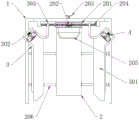
a glass part four-corner polishing production device comprises an outer frame 1, a sliding frame 3, a fixing piece 4 and a bottom shell 5, wherein a workbench 2 is installed inside the outer frame 1, and the axis of the outer frame 1 and the axis of the workbench 2 are on the same straight line; the two sliding frames 3 are symmetrically arranged about the axial lead of the outer frame 1, and the two sliding frames 3 are respectively arranged at two sides of the top of the outer frame 1;
a supporting plate 301 is arranged on one side of the carriage 3 close to the workbench 2, and the top of the supporting plate 301 and the top of the workbench 2 are positioned on the same horizontal plane; one end of the sliding frame 3 is provided with a guide groove 302, and one end of the guide groove 302 close to the workbench 2 is provided with a fixing plate 303;
the guide groove 302 is internally provided with a fixing member 4, one end of the fixing member 4 is connected with the inner wall of one side of the guide groove 302 through a first spring 401, and the other end of the fixing member 4 is fixedly connected with one side of the bottom shell 5.
In this embodiment, the workbench 2 includes a housing 201, a boss 205 and a guide rod 206, the housing 201 is installed at one end of the top of the workbench 2 close to the inner wall of the outer frame 1, a gear set 202 is installed inside the housing 201, and meanwhile, one end of the gear set 202 sequentially penetrates through the housing 201 and the outer frame 1 to form a rotating structure with the handle 203; the other two ends of the gear set 202 are both provided with a screw rod 204, and the other end of the screw rod 204 respectively penetrates through the two sides of the shell 201 to be connected with the fixing plate 303; the boss 205 is installed on the front side of the shell 201; guide bar 206 be the symmetry formula about the axis of workstation 2 and be provided with two sets ofly, and every guide bar 206 of group all is the symmetry formula and is provided with two to two sets of guide bars 206 are installed respectively between outer frame 1's both sides inner wall and workstation 2, two sets of guide bars 206 respectively with two balladeur train 3 sliding connection simultaneously.
In the invention, the handle 203 is rotated to simultaneously drive the screw rods 204 at two ends to synchronously rotate, so as to drive the sliding frames 3 at two sides to synchronously slide relatively along the guide rod 206, and further adjust the distance between the two sliding frames 3 to adapt to glass plates with different widths.
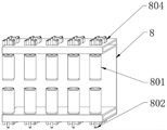
In this embodiment, the bottom case 5 includes six guide wheels 501, a polishing belt 502, a limiting member 503, a guide member 504, and a fixing frame 6, wherein the six guide wheels 501 are all installed at the top of the bottom case 5, the polishing belt 502 is wrapped around the outer sides of the six guide wheels 501, the limiting member 503 is installed at equal intervals on the inner end surface of the polishing belt 502, and the limiting member 503 is in a "T" shape; the guide members 504 are respectively installed on two sides of the outer wall of the bottom case 5, and the guide members 504 are slidably connected with the inner wall of the guide groove 302; the fixing frame 6 is arranged at one end of the top of the bottom shell 5 far away from the fixing piece 4, and the fixing frame 6 is of a hollow structure.
In the invention, in the process of operating the polishing belt 502, the limiting member 503 with a T-shaped structure can pass through two groups of guide rollers 801 in the same movable clamp 8, so that on the premise of not obstructing the operation of the polishing belt 502, the separation between the polishing belt 502 and the movable clamp 8 in the rotating process of the movable clamp 8 is effectively prevented, and the use stability is improved.
In this embodiment, the fixing frame 6 includes a first push rod 601, an adaptor 602, a second push rod 603 and a top cover 7, the axial line of the first push rod 601, the axial line of the fixing frame 6 and the axial line of the polishing belt 502 are all the same straight line, and the first push rod 601 is connected with the fixing frame 6 in a sliding manner; the adapter 602 is installed at two ends of one side of the fixed frame 6 far away from the fixed member 4, the adapter 602 is rotatably connected with the fixed frame 6, and meanwhile, the other end of the fixed frame 6 is rotatably connected with the movable clamp 8; the axial lead of the second push rod 603 and the axial lead of the first push rod 601 are the same straight line, the second push rod 603 is connected with one end of the first push rod 601, and the other end of the first push rod 601 is rotatably connected with one end of the movable clamp 8; two ends of the second push rod 603 are respectively connected with one end of a second spring 607 through a movable rod 604 and a third push rod 605, the third push rod 605 respectively penetrates through the guide sliding sleeve 606, and the guide sliding sleeve 606 and the second spring 607 are both fixed on the top of the bottom shell 5; the top cover 7 is arranged on the top of the bottom shell 5.
According to the glass polishing device, the fixed frame 6 and the movable clamps 8 are arranged, the movable clamps 8 are rotatably connected, the rotating angle range between the two movable clamps 8 is 0-90 degrees, in an initial state, the second spring 607 is matched with the first push rod 601 to push the two movable clamps 8 to extend forwards, the two movable clamps 8 are parallel to each other at the moment, the polishing belt 502 is further pushed to stretch forwards, the polishing belt 502 is ensured to be tightly attached to the side surface of glass in the polishing process, the polishing efficiency is improved, when the vertex angle of the glass extrudes the two movable clamps 8 inwards, the first push rod 601 contracts backwards and simultaneously drives the two movable clamps 8 to turn forwards, the polishing belt 502 on the surfaces of the two movable clamps 8 is further driven to continuously keep being tightly attached to the side edge of the glass, the corner of the glass is further polished, and the polishing efficiency is further improved.
In this embodiment, the first push rod 601, the second push rod 603, the movable rod 604, the third push rod 605, the guide sliding sleeve 606 and the second spring 607 form a telescopic structure, and the connection modes of the second push rod 603, the movable rod 604 and the third push rod 605 are all rotational connection, and the connection mode of the third push rod 605 and the guide sliding sleeve 606 is sliding connection.
According to the invention, the first push rod 601 can be assisted to push the two movable clamps 8 to be quickly restored to the initial positions through the telescopic structure, so that the use convenience is improved.
In this embodiment, the top cover 7 includes a top shell 701 and a belt transmission structure 704, the top shell 701 is installed on the top of the top cover 7, and the top of the top cover 7 is installed with a motor 702; the bottom of the motor 702 penetrates through the top shell 701 through a motor shaft 703 to form a rotating structure with a belt transmission structure 704, and two ends of the belt transmission structure 704 penetrate through the top cover 7 to form a rotating structure with the guide wheel 501.
In the invention, the motor 702 is matched with the belt transmission structure 704 to drive the guide wheel 501 to rotate so as to synchronously drive the polishing belt 502 to rotate, the rotating polishing belt 502 replaces a polishing grinding wheel to polish the edge of the glass, the polishing belt 502 has good elasticity, and can be attached to the edge of the glass in the polishing process, thereby improving the polishing effect.
In this embodiment, two sets of the movable clips 8 are provided, and two movable clips 8 are symmetrically provided about the axis of the first push rod 601, and the two movable clips 8 and the first push rod 601 form a rotating structure.
In the invention, the two movable clamps 8 push the polishing belt 502, so that the polishing belt 502 is kept in a tight state, and good transmission efficiency between the polishing belt 502 and the guide wheel 501 is ensured.
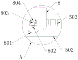
In this embodiment, the movable clamp 8 includes a guide roller 801 and an elastic sheet 804, the guide roller 801 is installed on the inner walls of the upper and lower sides of the movable clamp 8, the front end of the movable clamp 8 is in a groove-shaped structure, and the guide roller 801 penetrates through the groove-shaped structure of the movable clamp 8 and is tightly attached to the inner end surface of the polishing belt 502; one end of each guide roller 801 is provided with a connecting rod 802, and the connecting rods 802 penetrate through the sliding chutes 803 respectively; the sliding grooves 803 are respectively arranged at two sides of the movable clamp 8; the elastic sheet 804 is installed on the outer walls of the two sides of the movable clamp 8, and one end of the elastic sheet 804 is tightly attached to the connecting rod 802.
In the invention, the friction between the movable clamp 8 and the grinding belt 502 is reduced by the guide roller 801, so that the stability of the grinding belt 502 during grinding is improved.
In this embodiment, the guide rollers 801, the connecting rods 802, the sliding grooves 803 and the elastic pieces 804 are distributed at equal intervals, the diameter of the guide rollers 801 is equal to the distance between the end of the limiting member 503 and the inner end surface of the polishing belt 502, and the guide rollers 801 form a rotating structure.
In the present invention, the movable range of the guide roller 801 is restricted by the chute 803.
In this embodiment, the connection manner of the connecting rod 802 and the sliding groove 803 is a sliding connection, and the connecting rod 802 and the elastic piece 804 form a telescopic structure.
In the invention, a single guide roller 801 can be independently contracted through a telescopic structure, so that the gap between the grinding belt 502 and the edge of the glass plate is dynamically compensated, and the grinding effect is improved.
The working principle of the invention comprises the following processes:
firstly, horizontally placing a glass plate to be polished on the top of a workbench 2 and a supporting plate 301, then clockwise rotating a handle 203, driving two sliding frames 3 to slide along guide rods 206 by a gear set 202 in cooperation with a screw 204, so that the inner walls of the two sliding frames 3 are tightly attached to two sides of the glass plate, then pushing the glass plate to the inside of an outer frame 1, so that the top end of the glass plate is tightly attached to a boss 205, and at the moment, two top corners of the glass plate are respectively positioned in two guide grooves 302;
then, an external power supply is switched on, the two motors 702 are started simultaneously, the motor shaft 703 is matched with the belt transmission structure 704 to drive the guide wheel 501 to rotate, and the rotating guide wheel 501 drives the polishing belt 502 to rotate;
then, the bottom case 5 is pushed along the guide groove 302, the bottom case 5 starts to stretch the first spring 401 by the fixing member 4 during the sliding process, and simultaneously, the grinding belt 502 starts to contact the corner of the glass plate, and as the sliding distance of the bottom case 5 increases, the corner of the glass starts to press the two movable clips 8, and pushes the first push rod 601 inwards, the first push rod 601 begins to extrude the two second springs 607 through the second push rod 603, the movable rod 604 and the third push rod 605 in the process of retracting inwards until the included angle between the two movable clamps 8 is the same as the included angle of the two sides of the glass corner, at this time, the polishing belts 502 on the surfaces of the movable clamps 8 cling to the two sides of the glass corner, the two sides of the edge of the glass are polished, and in the polishing process, the elastic sheet 804 pushes the guide roller 801 and the polishing belt 502 to keep clinging to the side surface of the edge of the glass through the connecting rod 802, so that the overall polishing effect is improved.
The invention has the beneficial effects that:
in the invention, the edge of the glass is polished by the polishing belt 502 instead of a polishing grinding wheel, and the handle 203 is rotated, so that the screw rods 204 at two ends can be simultaneously driven to synchronously rotate, the sliding frames 3 at two sides are driven to synchronously slide relatively along the guide rod 206, and further, the distance between the two sliding frames 3 is adjusted to adapt to glass plates with different widths.
In the present invention, an included angle between the inner wall of the guide groove 302 and the carriage 3 is 45 °, the moving track of the bottom case 5 is limited by the guide groove 302, and the first spring 401 installed inside the guide groove 302 can assist the bottom case 5 to quickly return to the initial position after the machining is completed.
In the invention, a plurality of limiting pieces 503 with T-shaped structures are distributed on the inner end surface of the grinding belt 502 at equal intervals, and in the running process of the grinding belt 502, the limiting pieces 503 can pass through two groups of guide rollers 801 in the same movable clamp 8, so that on the premise of not hindering the running of the grinding belt 502, the grinding belt 502 and the movable clamp 8 are effectively prevented from being separated in the running process of the movable clamp 8, and the use stability is improved.
According to the glass polishing device, the fixed frame 6 and the movable clamps 8 are arranged, the movable clamps 8 are rotatably connected, the rotating angle range between the two movable clamps 8 is 0-90 degrees, in an initial state, the second spring 607 is matched with the first push rod 601 to push the two movable clamps 8 to extend forwards, the two movable clamps 8 are parallel to each other at the moment, the polishing belt 502 is further pushed to stretch forwards, the polishing belt 502 is ensured to be tightly attached to the side surface of glass in the polishing process, the polishing efficiency is improved, when the vertex angle of the glass extrudes the two movable clamps 8 inwards, the first push rod 601 contracts backwards and simultaneously drives the two movable clamps 8 to turn forwards, the polishing belt 502 on the surfaces of the two movable clamps 8 is further driven to continuously keep being tightly attached to the side edge of the glass, the corner of the glass is further polished, and the polishing efficiency is further improved.
In the invention, the movable clamp 8 is provided with the guide rollers 801, the connecting rod 802, the sliding chute 803 and the elastic sheet 804, and in the process of connecting the movable clamp 8 and the polishing belt 502, each guide roller 801 and the elastic sheet 804 form an elastic structure through the connecting rod 802, so that each guide roller 801 can independently stretch and retract in a small range, and because the cutting surface of the glass is not a flat surface and has a protruding sharp bulge, the position of the polishing belt 502 can be automatically adjusted according to the cutting surface of the glass in the rotating process by the small-range stretching structure, the damage of the polishing belt 502 caused by the overlarge pressure between the polishing belt 502 and the sharp bulge of the cutting surface of the glass is avoided, and the service life of the polishing belt 502 is prolonged.
The embodiments of the present invention are disclosed as the preferred embodiments, but not limited thereto, and those skilled in the art can easily understand the spirit of the present invention and make various extensions and changes without departing from the spirit of the present invention.
Claims (1)
1. A glass part four-corner polishing production device comprises an outer frame (1), a sliding frame (3), a fixing piece (4) and a bottom shell (5), and is characterized in that a workbench (2) is installed inside the outer frame (1), and the axis of the outer frame (1) and the axis of the workbench (2) are on the same straight line; the two sliding frames (3) are symmetrically arranged relative to the axial lead of the outer frame (1), and the two sliding frames (3) are respectively arranged at two sides of the top of the outer frame (1);
a supporting plate (301) is arranged on one side of the sliding frame (3) close to the workbench (2), and the top of the supporting plate (301) and the top of the workbench (2) are positioned on the same horizontal plane; one end of the sliding frame (3) is provided with a guide groove (302), and one end of the guide groove (302) close to the workbench (2) is provided with a fixing plate (303);
a fixing piece (4) is arranged in the guide groove (302), one end of the fixing piece (4) is connected with the inner wall of one side of the guide groove (302) through a first spring (401), and the other end of the fixing piece (4) is fixedly connected with one side of the bottom shell (5);
the workbench (2) comprises a shell (201), a boss (205) and a guide rod (206), the shell (201) is installed at one end, close to the inner wall of the outer frame (1), of the top of the workbench (2), a gear set (202) is installed inside the shell (201), and meanwhile one end of the gear set (202) sequentially penetrates through the shell (201), the outer frame (1) and the handle (203) to form a rotating structure; the other two ends of the gear set (202) are respectively provided with a screw rod (204), and the other end of the screw rod (204) respectively penetrates through the two sides of the shell (201) to be connected with the fixing plate (303); the boss (205) is arranged on the front side of the shell (201); the two groups of guide rods (206) are symmetrically arranged about the central axis of the workbench (2), two guide rods (206) are symmetrically arranged in each group, the two groups of guide rods (206) are respectively arranged between the inner walls of the two sides of the outer frame (1) and the workbench (2), and the two groups of guide rods (206) are respectively connected with the two sliding frames (3) in a sliding manner;
the bottom shell (5) comprises six guide wheels (501), a grinding belt (502), limiting pieces (503), guide pieces (504) and a fixing frame (6), wherein the six guide wheels (501) are arranged, the six guide wheels (501) are all installed at the top of the bottom shell (5), the grinding belt (502) wraps the outer sides of the six guide wheels (501), the limiting pieces (503) are installed on the inner end surface of the grinding belt (502) at equal intervals, and the limiting pieces (503) are of a T-shaped structure; the guide pieces (504) are respectively arranged on two sides of the outer wall of the bottom shell (5), and the guide pieces (504) are in sliding connection with the inner wall of the guide groove (302); the fixing frame (6) is arranged at one end of the top of the bottom shell (5) far away from the fixing piece (4), and the fixing frame (6) is of a hollow structure;
the fixing frame (6) comprises a first push rod (601), an adapter (602), a second push rod (603) and a top cover (7), the axial lead of the first push rod (601), the axial lead of the fixing frame (6) and the axial lead of the grinding belt (502) are all the same straight line, and the first push rod (601) is connected with the fixing frame (6) in a sliding manner; the adapter (602) is arranged at two ends of one side of the fixing frame (6) far away from the fixing piece (4), the adapter (602) is rotatably connected with the fixing frame (6), and meanwhile, the other end of the fixing frame (6) is rotatably connected with the movable clamp (8) respectively; the axial lead of the second push rod (603) and the axial lead of the first push rod (601) are the same straight line, the second push rod (603) is connected with one end of the first push rod (601), and the other end of the first push rod (601) is rotatably connected with one end of the movable clamp (8); two ends of the second push rod (603) are respectively connected with one end of a second spring (607) through a movable rod (604) and a third push rod (605), the third push rod (605) respectively penetrates through the guide sliding sleeve (606), and the guide sliding sleeve (606) and the second spring (607) are both fixed at the top of the bottom shell (5); the top cover (7) is arranged at the top of the bottom shell (5);
the first push rod (601), the second push rod (603), the movable rod (604), the third push rod (605), the guide sliding sleeve (606) and the second spring (607) form a telescopic structure, the second push rod (603), the movable rod (604) and the third push rod (605) are connected in a rotating mode, and meanwhile, the third push rod (605) is connected with the guide sliding sleeve (606) in a sliding mode;
the top cover (7) comprises a top shell (701) and a belt transmission structure (704), the top shell (701) is installed at the top of the top cover (7), and a motor (702) is installed at the top of the top cover (7); the bottom of the motor (702) penetrates through the top shell (701) through a motor shaft (703) to form a rotating structure with the belt transmission structure (704), and two ends of the belt transmission structure (704) penetrate through the top cover (7) to form a rotating structure with the guide wheel (501);
two groups of movable clamps (8) are arranged, two movable clamps (8) are symmetrically arranged on each group of movable clamps (8) relative to the axial lead of the first push rod (601), and the two movable clamps (8) and the first push rod (601) form a rotating structure;
the movable clamp (8) comprises a guide roller (801) and an elastic sheet (804), the guide roller (801) is installed on the inner walls of the upper side and the lower side of the movable clamp (8), the front end of the movable clamp (8) is of a groove-shaped structure, and meanwhile the guide roller (801) penetrates through the groove-shaped structure of the movable clamp (8) and is tightly attached to the inner end face of the grinding belt (502); one end of each guide roller (801) is provided with a connecting rod (802), and the connecting rods (802) penetrate through the sliding grooves (803) respectively; the sliding grooves (803) are respectively arranged at two sides of the movable clamp (8); the elastic sheet (804) is arranged on the outer walls of the two sides of the movable clamp (8), and one end of the elastic sheet (804) is tightly attached to the connecting rod (802);
the guide rollers (801), the connecting rods (802), the sliding grooves (803) and the elastic sheets (804) are distributed at equal intervals, the diameter of each guide roller (801) is equal to the interval between the tail end of the limiting piece (503) and the inner end face of the grinding belt (502), and the guide rollers (801) form a rotating structure;
the connecting rod (802) is connected with the sliding groove (803) in a sliding manner, and the connecting rod (802) and the elastic sheet (804) form a telescopic structure;
during the operation of the grinding belt (502), the limiting piece (503) passes through two groups of guide rollers (801) in the same movable clamp (8).
Priority Applications (1)
| Application Number | Priority Date | Filing Date | Title |
|---|---|---|---|
| CN202110112675.5A CN112917331B (en) | 2021-01-27 | 2021-01-27 | Glass spare four corners apparatus for producing that polishes |
Applications Claiming Priority (1)
| Application Number | Priority Date | Filing Date | Title |
|---|---|---|---|
| CN202110112675.5A CN112917331B (en) | 2021-01-27 | 2021-01-27 | Glass spare four corners apparatus for producing that polishes |
Publications (2)
| Publication Number | Publication Date |
|---|---|
| CN112917331A CN112917331A (en) | 2021-06-08 |
| CN112917331B true CN112917331B (en) | 2022-02-18 |
Family
ID=76167196
Family Applications (1)
| Application Number | Title | Priority Date | Filing Date |
|---|---|---|---|
| CN202110112675.5A Active CN112917331B (en) | 2021-01-27 | 2021-01-27 | Glass spare four corners apparatus for producing that polishes |
Country Status (1)
| Country | Link |
|---|---|
| CN (1) | CN112917331B (en) |
Families Citing this family (1)
| Publication number | Priority date | Publication date | Assignee | Title |
|---|---|---|---|---|
| CN114131705A (en) * | 2021-12-10 | 2022-03-04 | 湖南红崀山木业科技有限公司 | Corner one-time forming equipment for ecological plate processing |
Citations (10)
| Publication number | Priority date | Publication date | Assignee | Title |
|---|---|---|---|---|
| SU1514574A1 (en) * | 1987-06-03 | 1989-10-15 | Ki Polt I | Device for grinding surface of article |
| JP2002028844A (en) * | 2000-07-14 | 2002-01-29 | Kyosan Electric Mfg Co Ltd | Tape-polishing device |
| CN1421903A (en) * | 2001-11-26 | 2003-06-04 | 株式会社东芝 | Production method of semiconductor and grinding apparatus |
| CN206677720U (en) * | 2017-04-27 | 2017-11-28 | 四川建筑职业技术学院 | One kind has contractile abrasive-belt type grinding machine |
| EP3287235A1 (en) * | 2016-06-29 | 2018-02-28 | Chongqing University | Abrasive belt grinding center applicable to grinding and polishing machining of overall profile of blisk |
| CN109176253A (en) * | 2018-11-02 | 2019-01-11 | 新昌县奔力机械有限公司 | A kind of spare parts processing machinery corner grinding device |
| CN209175470U (en) * | 2018-11-02 | 2019-07-30 | 西安红安重工机械有限责任公司 | A kind of spare parts processing machinery corner grinding device |
| CN110614560A (en) * | 2019-11-06 | 2019-12-27 | 湖州师范学院 | Panel edge grinding device |
| CN110774127A (en) * | 2019-11-05 | 2020-02-11 | 刘贤东 | Full-automatic grinding device is used in processing of square glass turning |
| CN111152101A (en) * | 2020-01-14 | 2020-05-15 | 大同新成新材料股份有限公司 | Intelligent carbon sliding plate outer arc polishing equipment convenient to adjust and polishing method thereof |
Family Cites Families (6)
| Publication number | Priority date | Publication date | Assignee | Title |
|---|---|---|---|---|
| JP2000153168A (en) * | 1998-11-18 | 2000-06-06 | Saiken Kogyo Kk | Glass grinding and glass grinder |
| DE102014208319B4 (en) * | 2014-05-05 | 2021-05-06 | Supfina Grieshaber Gmbh & Co. Kg | Tape finishing device and method of operating a tape finishing device |
| CN104440475A (en) * | 2014-11-27 | 2015-03-25 | 合肥京东方光电科技有限公司 | Belt transmission device and grinding device |
| CN106181670B (en) * | 2016-08-31 | 2018-03-30 | 广东龙德创展科技有限公司 | A kind of belt edge sander and its piano type sheet material corner polishing structure |
| CN109623542A (en) * | 2018-11-12 | 2019-04-16 | 盐城唯宏特通用机械有限公司 | It is a kind of with chip removal device and facilitate storage object beveler |
| CN112045536A (en) * | 2020-08-29 | 2020-12-08 | 东莞市龙飞数控科技有限公司 | Automobile special-shaped plastic part processing equipment with surface modification and hot stamping functions |
-
2021
- 2021-01-27 CN CN202110112675.5A patent/CN112917331B/en active Active
Patent Citations (10)
| Publication number | Priority date | Publication date | Assignee | Title |
|---|---|---|---|---|
| SU1514574A1 (en) * | 1987-06-03 | 1989-10-15 | Ki Polt I | Device for grinding surface of article |
| JP2002028844A (en) * | 2000-07-14 | 2002-01-29 | Kyosan Electric Mfg Co Ltd | Tape-polishing device |
| CN1421903A (en) * | 2001-11-26 | 2003-06-04 | 株式会社东芝 | Production method of semiconductor and grinding apparatus |
| EP3287235A1 (en) * | 2016-06-29 | 2018-02-28 | Chongqing University | Abrasive belt grinding center applicable to grinding and polishing machining of overall profile of blisk |
| CN206677720U (en) * | 2017-04-27 | 2017-11-28 | 四川建筑职业技术学院 | One kind has contractile abrasive-belt type grinding machine |
| CN109176253A (en) * | 2018-11-02 | 2019-01-11 | 新昌县奔力机械有限公司 | A kind of spare parts processing machinery corner grinding device |
| CN209175470U (en) * | 2018-11-02 | 2019-07-30 | 西安红安重工机械有限责任公司 | A kind of spare parts processing machinery corner grinding device |
| CN110774127A (en) * | 2019-11-05 | 2020-02-11 | 刘贤东 | Full-automatic grinding device is used in processing of square glass turning |
| CN110614560A (en) * | 2019-11-06 | 2019-12-27 | 湖州师范学院 | Panel edge grinding device |
| CN111152101A (en) * | 2020-01-14 | 2020-05-15 | 大同新成新材料股份有限公司 | Intelligent carbon sliding plate outer arc polishing equipment convenient to adjust and polishing method thereof |
Also Published As
| Publication number | Publication date |
|---|---|
| CN112917331A (en) | 2021-06-08 |
Similar Documents
| Publication | Publication Date | Title |
|---|---|---|
| CN114227436B (en) | Cold-rolled steel sheet side grinding device | |
| CN112917331B (en) | Glass spare four corners apparatus for producing that polishes | |
| CN108620879A (en) | A kind of square steel cutting polishing all-in-one machine | |
| CN203156506U (en) | Wood floor polisher | |
| CN113649867A (en) | A industrial robot for work piece side is polished | |
| CN113319707B (en) | Metal furniture supports pedestal surface polishing machine | |
| CN112894538B (en) | Optical lens manufacturing and processing method | |
| CN212886823U (en) | Lock body grinding and polishing machine | |
| CN109015189A (en) | A kind of glass corner grinding device | |
| CN217914497U (en) | Curtain wall glass's edging ware | |
| CN112339344A (en) | Production process of degradable paper-plastic packaging bag | |
| CN210209887U (en) | Adjustable polishing head mechanism for polishing surface of tank body | |
| CN112108967B (en) | Finish machining machine and process for manufacturing rubber sealing product | |
| CN114833693A (en) | Wood polishing equipment | |
| CN109158968A (en) | A kind of highly-efficient glass production side grinding device | |
| CN115179356A (en) | Spc floor production line cutting device with adjustable | |
| CN219293618U (en) | Two-shaft polishing machine with protection mechanism | |
| CN210413971U (en) | Deburring device for rubber product production | |
| CN115672876B (en) | Tire mold laser cleaning device based on snake-shaped robot and application method | |
| CN209998913U (en) | Polishing wire drawing machine for producing stainless steel heat-insulating barrels | |
| CN218855122U (en) | Clamp suitable for cleaning multi-size optical filter | |
| CN212886578U (en) | Lateral wall grinding device is used in bar copper production convenient to stabilize centre gripping | |
| CN115338726B (en) | Production equipment for corner treatment of diatom ooze element plate and corner treatment method | |
| CN217991947U (en) | Glazed tile trimming device | |
| CN220145600U (en) | Polishing mechanism for glass processing |
Legal Events
| Date | Code | Title | Description |
|---|---|---|---|
| PB01 | Publication | ||
| PB01 | Publication | ||
| SE01 | Entry into force of request for substantive examination | ||
| SE01 | Entry into force of request for substantive examination | ||
| TA01 | Transfer of patent application right |
Effective date of registration: 20220127 Address after: 266000 room 3-3025, No. 3, dagongdao Road, Huangdao District, Qingdao City, Shandong Province Applicant after: Qingdao fusion Photoelectric Technology Co.,Ltd. Address before: 571199 Building 1, rongchuang wujihai, Haiyu east line, g223, Qiongshan District, Haikou City, Hainan Province Applicant before: Li Lvju |
|
| TA01 | Transfer of patent application right | ||
| GR01 | Patent grant | ||
| GR01 | Patent grant |