CN112914515A - Measuring device and non-invasive treatment device for skin properties - Google Patents
Measuring device and non-invasive treatment device for skin properties Download PDFInfo
- Publication number
- CN112914515A CN112914515A CN202110301010.9A CN202110301010A CN112914515A CN 112914515 A CN112914515 A CN 112914515A CN 202110301010 A CN202110301010 A CN 202110301010A CN 112914515 A CN112914515 A CN 112914515A
- Authority
- CN
- China
- Prior art keywords
- axis
- detection
- skin
- treatment
- optical
- Prior art date
- Legal status (The legal status is an assumption and is not a legal conclusion. Google has not performed a legal analysis and makes no representation as to the accuracy of the status listed.)
- Pending
Links
Images


Classifications
-
- A—HUMAN NECESSITIES
- A61—MEDICAL OR VETERINARY SCIENCE; HYGIENE
- A61B—DIAGNOSIS; SURGERY; IDENTIFICATION
- A61B18/00—Surgical instruments, devices or methods for transferring non-mechanical forms of energy to or from the body
- A61B18/18—Surgical instruments, devices or methods for transferring non-mechanical forms of energy to or from the body by applying electromagnetic radiation, e.g. microwaves
- A61B18/20—Surgical instruments, devices or methods for transferring non-mechanical forms of energy to or from the body by applying electromagnetic radiation, e.g. microwaves using laser
- A61B18/203—Surgical instruments, devices or methods for transferring non-mechanical forms of energy to or from the body by applying electromagnetic radiation, e.g. microwaves using laser applying laser energy to the outside of the body
-
- A—HUMAN NECESSITIES
- A61—MEDICAL OR VETERINARY SCIENCE; HYGIENE
- A61B—DIAGNOSIS; SURGERY; IDENTIFICATION
- A61B5/00—Measuring for diagnostic purposes; Identification of persons
- A61B5/0059—Measuring for diagnostic purposes; Identification of persons using light, e.g. diagnosis by transillumination, diascopy, fluorescence
-
- A—HUMAN NECESSITIES
- A61—MEDICAL OR VETERINARY SCIENCE; HYGIENE
- A61B—DIAGNOSIS; SURGERY; IDENTIFICATION
- A61B5/00—Measuring for diagnostic purposes; Identification of persons
- A61B5/44—Detecting, measuring or recording for evaluating the integumentary system, e.g. skin, hair or nails
- A61B5/441—Skin evaluation, e.g. for skin disorder diagnosis
-
- A—HUMAN NECESSITIES
- A61—MEDICAL OR VETERINARY SCIENCE; HYGIENE
- A61N—ELECTROTHERAPY; MAGNETOTHERAPY; RADIATION THERAPY; ULTRASOUND THERAPY
- A61N5/00—Radiation therapy
- A61N5/06—Radiation therapy using light
- A61N5/0613—Apparatus adapted for a specific treatment
- A61N5/0616—Skin treatment other than tanning
-
- A—HUMAN NECESSITIES
- A61—MEDICAL OR VETERINARY SCIENCE; HYGIENE
- A61B—DIAGNOSIS; SURGERY; IDENTIFICATION
- A61B18/00—Surgical instruments, devices or methods for transferring non-mechanical forms of energy to or from the body
- A61B2018/00315—Surgical instruments, devices or methods for transferring non-mechanical forms of energy to or from the body for treatment of particular body parts
- A61B2018/00452—Skin
- A61B2018/00458—Deeper parts of the skin, e.g. treatment of vascular disorders or port wine stains
-
- A—HUMAN NECESSITIES
- A61—MEDICAL OR VETERINARY SCIENCE; HYGIENE
- A61B—DIAGNOSIS; SURGERY; IDENTIFICATION
- A61B18/00—Surgical instruments, devices or methods for transferring non-mechanical forms of energy to or from the body
- A61B2018/00315—Surgical instruments, devices or methods for transferring non-mechanical forms of energy to or from the body for treatment of particular body parts
- A61B2018/00452—Skin
- A61B2018/0047—Upper parts of the skin, e.g. skin peeling or treatment of wrinkles
-
- A—HUMAN NECESSITIES
- A61—MEDICAL OR VETERINARY SCIENCE; HYGIENE
- A61B—DIAGNOSIS; SURGERY; IDENTIFICATION
- A61B18/00—Surgical instruments, devices or methods for transferring non-mechanical forms of energy to or from the body
- A61B2018/00636—Sensing and controlling the application of energy
- A61B2018/00773—Sensed parameters
- A61B2018/00779—Power or energy
- A61B2018/00785—Reflected power
-
- A—HUMAN NECESSITIES
- A61—MEDICAL OR VETERINARY SCIENCE; HYGIENE
- A61N—ELECTROTHERAPY; MAGNETOTHERAPY; RADIATION THERAPY; ULTRASOUND THERAPY
- A61N5/00—Radiation therapy
- A61N5/06—Radiation therapy using light
- A61N2005/0626—Monitoring, verifying, controlling systems and methods
- A61N2005/0627—Dose monitoring systems and methods
- A61N2005/0628—Dose monitoring systems and methods including a radiation sensor
Abstract
Non-invasive measurement apparatus (30) and methods for skin property measurement using laser light are provided, the apparatus comprising a detection module (70) and an imaging module (50). Non-invasive treatment apparatus (130,230,330,430) and methods including the measurement apparatus/method are also provided. The detection module (70) provides a detection beam (82) that enters the skin along a detection axis (71). The probe beam (82) is separate from any treatment radiation beam (22) so that the probe beam (82) can be optimized for measurement. A more reliable skin measurement system is provided because it measures multiple positions along the detection axis (71) within the detection zone (95). The measurement device and method may further comprise a processing module (110) or processing step. The measured skin parameters can then be used directly to control the treatment parameters. This results in a skin treatment device (10) that is not only effective but delivers reproducible results.
Description
The application is a divisional application with application number 201480036135.1 entitled "measuring device and non-invasive treatment device for skin characteristics" filed on international application date 2014, 06, 25, 2015, 12, 24, and entering the chinese national stage.
Technical Field
The present invention relates generally to the measurement of skin properties, particularly properties related to skin treatment, using electromagnetic treatment radiation, such as laser light. It relates more particularly to non-invasive devices for skin treatment, where these measurements are made and used to modify or control the skin treatment.
Background
Various forms of electromagnetic radiation, particularly laser beams, have been used on the skin for many years for various treatments such as hair removal, skin rejuvenation to reduce wrinkles, and treatment of conditions such as acne, solar keratosis, surface blemishes, scar tissue, discoloration, vascular damage, acne treatment, cellulite, and tattoo removal. It is well known that some of these treatments may be performed to provide a therapeutic effect, but often they are all performed to provide a non-therapeutic or cosmetic effect. Most of these treatments rely on photothermolysis (photothermolysis), where the treatment radiation is targeted at the treatment site. For example, to treat wrinkles, the dermis layer is destroyed by heat (thermolysis) to induce a wound response without damaging the epidermis.
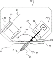
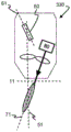
In some treatments, the heating by electromagnetic radiation occurs in the dermis layer by using radiation that can penetrate the skin as far as the dermis layer. Fig. 1 schematically shows a skin treatment device 10 known in the art comprising a radiation source 20 and a beam shaping and guiding assembly 27. The radiation source 20 provides an incident radiation beam 22 suitable for treatment of human or animal skin. The radiation used may be any type of electromagnetic or thermal radiation that provides a beneficial effect in the skin. For example, when using laser light, the skin treatment device 10 may comprise a pulsed laser source 20, such as a Nd: YAG laser emitting at 1064nm and 1-1000ps pulse duration.
Beam shaping and directing assembly 27 receives radiation beam 22 from radiation source 20 and forms radiation beam 22 having desired characteristics to exit apparatus 10 along process axis 21.
For example, when using laser light, these beam shaping and directing components 27 may be optical elements, such as mirrors, lenses, beam splitters, prisms, etc., for directing the laser beam 22 away from the apparatus along the treatment axis 21 and for focusing the beam 22 within the skin at a treatment location 90 on the treatment axis 21.
In other examples, if radio frequency radiation is used, these beam shaping and guiding components 27 may be waveguides, apertures, reflectors, etc. for guiding the radio frequency beam 22 away from the apparatus along the treatment axis 21.
The skin comprises a plurality of layers having different radiation transmission and absorption properties. The epidermis 16 is composed of the outermost layer and forms a waterproof protective barrier. The outermost layer of the epidermis is the stratum corneum, which, due to its microscopic fluctuations in roughness, impedes the coupling of radiation (particularly light) between the device 10 and the skin. Typically, a radiation coupler 12 is used on the device 10 between where the radiation beam exits and where the radiation enters the skin on the skin surface. This optimizes the penetration of the treatment radiation beam 22 into the skin. For example, in the case of laser beam 22, optical coupler 12 may be used that includes lenses, mirrors, prisms, index-matching fluids, or combinations thereof. The dermis 17 is located beneath the epidermis 16, the dermis 17 being the area targeted by many skin treatments.
If the device 10 is used to reduce wrinkles in the skin, the treatment site 90 is in the collagen of the dermis 17 so that microscopic lesions are formed at the treatment site, which results in new collagen formation.
The laser treatment device 10 makes use of the fact that the skin transmits electromagnetic radiation to be focused to a very small focal spot in the dermis 17. To maximize this effect, the wavelength of the laser is between 800 and 1100 nm. In this range, transmission is high and scattering and linear absorption are low. Thus, using phenomena utilized for skin treatment, such as photothermolysis or Laser Induced Optical Breakdown (LIOB), can be achieved easily, accurately (i.e. very locally) and efficiently. However, the use of other wavelengths is not excluded.
An increasing number of such non-invasive skin treatment devices are provided for use by consumers rather than medical professionals. Such use is primarily for cosmetic or non-therapeutic reasons. Such home use brings new problems such as safety and treatment efficacy. This is particularly important when the radiation source 20 is high powered (e.g., a laser).
For successful and safe skin treatment, it is critical that an appropriate amount of energy be delivered to the treatment site 90. Delivery of too much energy results in undesirable side effects such as scarring or burning of the skin. Too little energy delivery results in a less effective treatment. Moreover, even under normal circumstances, the reproducibility of the processing results may vary from person to person, even between anatomical regions of the same person. This is due to the inherent variability of skin properties, which severely affects the efficiency of energy delivery.
US 2005/0154382 a1 discloses a handheld dermatological apparatus for visualizing a skin treatment area before, during or after a treatment with treatment energy. This known device comprises an illumination source for illuminating a treatment area of the skin and an image capturing device. The apparatus further includes an optical system for directing radiation onto an image capture device, the radiation emanating from the treatment area in response to illumination by the illumination source, the image capture device being capable of forming an image of the treatment area. Depending on the wavelength of the light generated by the illumination source, the device is used for visualization of epidermal targets, for visualization of targets at depths up to about 1 millimeter below the skin, or for visualization of deeper targets up to about 3 millimeters below the skin surface. The optical axis of the illumination source and the common optical axis of the image capture device and the optical system are at an angle to each other. During use, these optical axes have a skewed orientation relative to the skin surface.
There is therefore a need for a radiation skin treatment device that is not only effective but delivers reproducible results.
Disclosure of Invention
It is an object of the present invention to provide a non-invasive measurement device and method for measuring skin properties related to a skin treatment.
According to the invention, this object is achieved by means of a non-invasive measuring device for measuring skin properties using laser light, the device comprising a detection module and an imaging module, wherein:
the detection module comprises a first optical system and a laser source for generating a probe beam, the detection module being configured and arranged such that, in use, the probe beam exits the device along a probe axis and impinges on an outer surface of the skin to be treated; the first optical system is configured and arranged to direct, in use, a probe light beam to a probe region within the skin;
an imaging module comprising a second optical system and an optical detector array disposed along a detector axis comprised in an image plane of the second optical system, wherein the second optical system has an imaging optical axis intersecting the detection axis,
the non-invasive measuring device is characterized in that the second optical system is configured and arranged to form, in use, an image of a plurality of detection positions distributed along a detection axis within the detection zone on a plurality of light detecting elements comprised in the optical detector array, respectively, wherein the plurality of detection positions lie in an object plane of the second optical system, and wherein an angle between the detection axis and the imaging optical axis is equal to an angle between the imaging optical axis and the detector axis.
The object of the invention is also achieved by providing a method for non-invasive measurement of skin properties using a device for generating laser light, the device comprising a detection module and an imaging module,
the method comprises the following steps:
-providing a probe module comprising a first optical system and a laser source for generating a probe beam;
-configuring and arranging the detection module such that, in use, a detection beam exits the device along a detection axis and impinges on an outer surface of the skin to be treated;
-configuring and arranging the first optical system to direct, in use, a probe light beam to a probe region within the skin;
-providing an imaging module comprising a second optical system and an optical detector array, the optical detector array being disposed along a detector axis comprised in an image plane of the second optical system, and the second optical system having an imaging optical axis intersecting the probing axis;
the method for non-invasive measurement is characterized in that the second optical system is configured and arranged to form, in use, an image of a plurality of detection positions distributed along a detection axis within the detection zone on a plurality of light detection elements comprised in the optical detector array, respectively, wherein the plurality of detection positions lie in an object plane of the second optical system, and wherein an angle between the detection axis and the imaging optical axis is equal to an angle between the imaging optical axis and the detector axis.
The invention is based on the insight that skin measurement devices known in the art are inherently limited in that they only measure specific parameters of the skin at the treatment site during application of the treatment radiation. The invention provides a probe beam entering the skin along a probe axis. The probe beam is a separate radiation beam from the processing radiation beam (which may be used before, during or after the measurement) so that the characteristics of the probe beam can be predetermined prior to the measurement. The detection module can thus be optimized for the measurement.
A second insight is that, although the properties of the treatment site are important, the treatment radiation beam passes through the skin between the outer layer of the skin and the treatment site, and the energy directed to the treatment site will diffuse to the surrounding tissue. The invention thus provides a more reliable skin measurement system, since it measures a plurality of positions along the detection axis within the detection zone. Since the treatment location (or will be after the measurement) is comprised within the detection zone, the invention measures the skin properties at the treatment location along the detection axis as well as at the surrounding points. Known measuring devices such as described in US 2005/0154382, US 2007/0252997 and US 2010/0130969 do not image multiple points along the probe axis.
A third insight is that when the imaging module images a plurality of positions, a more reliable measurement is provided. Many measurement devices known in the art, such as the device described in US 2008/0215038, simply form an image of the top surface of the skin and attempt to interpret the skin properties from the image. Since the invention comprises an imaging module and a detection module, the angle between the detection axis and the imaging optical axis is predetermined, and the angle between the detection axis and the outer layer of the skin is also predetermined. The second optical system is configured and disposed such that the plurality of dots are in an object plane of the second optical system and such that the optical detector array is disposed in an image plane of the second optical system. This means that a plurality of points are imaged simultaneously using a plurality of light detecting elements comprised in the detector array, respectively.
In other words, the measuring device provides a segmented optical depth distribution of the detection axis comprising a plurality of points, which are treatment-related positions in the skin, by performing measurements during or before or after the treatment. The measured skin parameters may then be used to set or modify treatment parameters, or indicate that no further treatment is required.
Thus, the measurement device and method are fast, accurate and can provide appropriate skin physiological information in relation to optimization of the radiation treatment.
It may be advantageous to further configure the measurement device such that the detector axis is comprised in a plane thereof comprising the probing axis and the imaging optical axis. This may result in less aberration of the image on the optical detector array, reducing the need to correct the image to compensate for detector axes not being in the same plane.
It may also be advantageous to configure and arrange the measuring device such that the angle subtended by the detection axis and the imaging optical axis is in the range of 20 to 90 degrees. The use of an imaging module means that there is an objective degree of flexibility in the location of each component within the measurement device, allowing the size of the device to be minimized or limited to make handling simpler. This is particularly advantageous when the measuring device is used by a consumer.
It may also be advantageous to configure and arrange the measuring device such that during operation of the measuring device the angle subtended by the probe axis and the outer surface of the skin lies in the range 45 to 90 degrees. In order to be able to make measurements at a plurality of points, the probe beam must penetrate the skin to reach the desired location of the treatment site, so that angles larger than 45 degrees are preferred. The images of the plurality of detection locations may be affected by the distance between each detection location and the outer surface of the skin and the tissue type. Therefore, it is preferred to deploy the imaging optical axis such that the distance between the outer surface of the skin and each detection location is as similar as possible.
It may even be more advantageous to configure and arrange the measuring device such that the detector axis and the detection axis are parallel to each other. This may be achieved by predefining the lens plane of the second optical system so as to be parallel to the detection axis. Although the optical detector array may be tilted from this parallel position to compensate for any deviation from parallelism of the lens planes, the parallel detector axis configuration is expected to provide the simplest and fastest measurement system.
It may be advantageous that the measuring method further comprises:
-processing the image detected by the array of optical detectors to generate one or more control parameters;
-applying one or more control parameters to determine an operating parameter of the probing laser source and/or the first optical system.
This makes it possible for the skin properties measured by the device to be used immediately to improve or modify the measurement. For example, if the average intensity is too low, the operating parameters of the probing laser source may be adapted to provide more energy.
The object of the invention is also achieved by providing a non-invasive treatment device for skin treatment using electromagnetic treatment radiation, the device comprising a measurement device according to the invention and the treatment device further comprising a treatment module, wherein:
the treatment module comprises a treatment radiation source for providing a treatment radiation beam and a beam shaping and guiding assembly, the treatment module being configured and arranged such that, in use, the treatment radiation beam exits the device along a treatment axis and impinges on an outer surface of skin to be treated; the beam shaping and directing assembly is configured and arranged to direct, in use, a radiation treatment beam to a treatment location disposed within the detection zone.
The measuring method according to the invention can be used in a method for non-invasive skin treatment using electromagnetic treatment radiation, the treatment method further comprising:
-providing a treatment module comprising a treatment radiation source for providing a treatment radiation beam and a beam shaping and guiding assembly;
the treatment module is configured and arranged such that, in use, a treatment radiation beam exits the device along a treatment axis and impinges on an outer surface of skin to be treated;
the beam shaping and directing assembly is configured and arranged to direct, in use, a beam of treatment radiation to a treatment location disposed within the detection zone.
By including the processing module into the measurement device, a processing device is provided. The angle between the detection axis and the treatment axis may be predetermined, thus enabling the treatment position to be at a desired position within the detection zone. This improves the reproducibility of the measurement, since the positional difference between the detection zone and the processing position is limited.
It may be advantageous that the processing method further comprises:
-processing the image detected by the optical detector array intensity to generate one or more control parameters;
-applying one or more control parameters to determine operating parameters of the treatment radiation source and/or the beam shaping and steering assembly.
Thereby, the skin properties measured by the device can be immediately used to improve or modify the treatment. For example, if the skin properties indicate that the presence of collagen has not been detected, the location of the treatment site may be altered.
If the treatment radiation is a laser, it may be particularly advantageous to configure and arrange the treatment module as described in such a way that the treatment axis coincides with the detection axis. This further improves the reproducibility, since the processing location is more likely to be deployed in the detection zone.
Drawings
Figure 1 diagrammatically shows a non-invasive radiation treatment apparatus known in the art in the process of treating skin;
fig. 2 shows a first embodiment 30 of a non-invasive measurement device for measuring skin properties using laser light, comprising a detection module 70 and an imaging module 50;
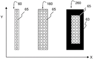
FIG. 3 depicts three examples 60, 160, 260 of suitable optical detector arrays;
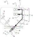
fig. 4 depicts a second embodiment 130 of a non-invasive measurement device for measuring skin properties using laser light, comprising a detection module 70, an imaging module 50 and a processing module 110;
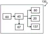
FIGS. 5A and 5B schematically illustrate possible control connections between different components of the first embodiment 30 and the second embodiment 130, respectively; and
fig. 6A to 6D schematically illustrate the relative angles between the detection axis 71, the imaging optical axis 51 and the skin outer surface axis 11 for the first 30 and second 130, third 230, fourth 330 and fifth 430 embodiments, respectively.
It should be noted that items which have the same reference numbers in different figures, have the same structural features and the same functions, or are the same signals. When the function and/or structure of such an item has been explained, it is not necessary to repeat the explanation thereof in the detailed description.
Detailed Description
Fig. 2 illustrates a first embodiment 30 of the present invention. Depicting a non-invasive measurement device 30 for making measurements of skin properties using laser light. The measurement device includes a detection module 70 and an imaging module 50 having a fixed relative disposition.
The detection module comprises a laser source 80 and a first optical system 87 for receiving laser light from the source 80 and directing a laser beam 82 to an opening in the measurement apparatus 30. The detection module 70 is configured and arranged such that, in use, a detection beam 82 exits the device 30 along the detection axis 71 and impinges on the outer surface of the treated skin. The first optical system 87 is configured and arranged to, in use, direct the probe light beam 82 to a detection zone 95 within the skin.
The detection laser source 80 is selected to provide laser light that penetrates the skin to a sufficient depth with appropriate characteristics according to expected physiological changes expected in the detection zone 95 of the skin during radiation treatment, and the method is selected to measure relevant skin characteristics.
The apparatus 30 may also include an optical coupler 12 to optimize energy delivery to the treatment location 90. Any suitable optical coupler 12, such as those known in the art, may be used.
The imaging module 50 comprises a second optical system 67 and an optical detector array 60, the optical detector array 60 being disposed along a detector axis 61 comprised in an imaging plane of the second optical system 67. The second optical system 67 is configured and arranged such that, in use, images of a plurality of detection positions distributed along the detection axis 71 within the detection zone 95 are obtained on a plurality of optical detectors comprised in the optical detector array 60, respectively. Due to the fixed relative disposition of the detection 70 and the imaging module 50 within the apparatus 30, the imaging optical axis 51 of the optical system 67 intersects the detection axis 75 within the detection zone 95.
As depicted in fig. 3, the optical detector array 60, 160, 260 may be a linear array of individual light sensors 65-in other words, a plurality of light sensors are disposed at equal distances from each other along the longitudinal axis. Typically, the light collected by the optical detector arrays 60, 160, 260 is converted to electrical signals via electrical circuitry, which may be built into the array substrate. Each of the plurality of detection locations is imaged onto a detector array, onto one or more optical detectors.
Since the imaging module 50 images multiple probe positions along the probe axis 71, the detector array 60 needs to be rectangular-that is, the longitudinal axis of the array 60 is disposed along the detector axis 61. In other words, if the detector during use comprises a matrix of Y light detecting elements 65 in a direction extending along the detector axis 61 multiplied by X light detecting elements 65 in a direction extending along another axis perpendicular to the detector axis 61, Y will be larger than X. Y is the direction of the longitudinal axis of the detector array 60.
In a first example 60 depicted in fig. 3, X is 1 and Y is 14. This makes it suitable for measuring 14 probe positions along the probe axis 71. This may be a linear CCD detector, for example.
In the second example 160 of fig. 3, X is 3 and Y is 14. This also makes it suitable for measuring 14 probe positions along the probe axis 71. In that case, only signals from the central columns of the detector array 160 (extending in the Y-direction) are considered, or signals from each row (extending in the X-direction) are combined in some way, such as averaging. Similarly, the light sensors 65 in the Y-direction may also be combined in some way, for example to measure 7 detection positions along the detection axis 71. If a plurality of light sensors 65 are used in the Y-direction, a significantly increased spatial information about the process distribution, e.g. the lesion width, can be obtained and a greater flexibility in laser processing efficiency is achieved.
In the third example 260 of fig. 3, a linear array, such as a CCD array, is formed using a large number of photosensors 65 extending in both the X and Y directions, but the unwanted photosensors are covered with a mask 63. Alternatively, the electrical signals from the light sensor 65 that are not needed may simply be ignored or may not be used when processing the signals.
The ratio of Y to X of the light detecting element is preferably greater than or equal to 5 to 1.
Multiple detectors are known in the art, such as in published U.S. patent 6,413,257. This patent discloses the use of multiple detectors to monitor the energy characteristics of skin tissue during treatment. Two to four infrared detectors are deployed such that they measure the radial dependence of the diffuse radiation emitted from the treatment site. Treatment radiation enters the skin at 90 degrees and the detectors are deployed at different distances from the entry point of the skin. However, the deployed detector is a simple infrared intensity detector-and does not form an image of the processing location.
The imaging module 50 may then be further configured to detect the desired optical signals from the skin by additionally providing optical components such as wavelength filters thereto and/or by appropriate processing 40 of the signals from the optical detector array 60. The required configuration depends on the type of treatment to be used for the measured skin property, and the positioning of the treatment location 90 in the skin.
Example 1: the optical signal is a Second Harmonic Generation (SHG) signal, which may indicate the presence of collagen. The probe laser source 80 may then be pulsed at a wavelength in the range of 700 to 2200nm (in the femtosecond to nanosecond range). The measured optical signal will depend on the relevant skin properties, i.e. the denatured state of the collagen, the depth of the dermis 17 and the thickness of the epidermis 16.
Example 2: the optical signal is 1-photon and 2-photon excited autofluorescence, which can indicate the presence of stratum corneum (i.e., keratin and lipids), epidermal cells, nad (p) H, collagen, elastin, hair. The detection laser source 80 for 1-photon excitation may be a continuous wave laser source operating at a wavelength in the range of 300 to 500nm, or for 2-photon excitation it may be pulsed (in the femtosecond to nanosecond range) operating at a wavelength in the range of 600 to 1000 nm. The measured optical signal will depend on the relevant skin properties, i.e. stratum corneum thickness, epidermis 16 thickness, dermis 17 depth, hair thickness, hair depth, melanin concentration, basal layer depth and melanocyte depth.
Example 3: the optical signal is Rayleigh-scattering (Rayleigh-scattering), which may indicate the presence of scattering centers. The probe laser source 80 may then be a continuous wave or pulsed laser source operating at a wavelength in the range of 350 to 1100 nm. The measured optical signal will depend on the relevant skin properties, i.e. melanocyte depth, basal layer depth, thickness of the epidermis 16 and tissue coagulation status.
Example 4: the optical signal is Raman scattering (Raman-scattering), which may indicate the presence of lipids, water or collagen. The probe laser source 80 may then be a continuous wave or pulsed nanosecond range laser source operating at a wavelength in the range of 350 to 1100 nm. The measured optical signal will depend on the relevant skin properties, i.e. stratum corneum thickness, water concentration and collagen denaturation status.
Example 5: the optical signal is a second or third harmonic-generated signal, which may be indicative of the presence of a tissue interface or membrane. The probe laser source 80 may then be pulsed at a wavelength in the range 1050 to 3300nm (in the femtosecond to nanosecond range). The measured optical signal will depend on the relevant skin properties, i.e. the thickness of the stratum corneum, the thickness of the epidermis 16 and the depth of the dermis 17.
Example 6: the optical signal is infrared thermal radiation, which may indicate the presence of heat-generating tissue. The probe laser source 80 may then be a continuous wave or pulsed laser source operating at a wavelength in the range of 350 to 1100 nm. The measured optical signal will depend on the relevant skin property, i.e. temperature.
The skilled person will be able to configure the measurement device 30 to perform the required measurements. This can be done using simulation calculations or based on trial and error.
The skilled person will also appreciate that the measurement device may comprise a plurality of detection 70 and imaging modules 50, each configured to perform measurements of one or more optical properties. Each module may also be configured to perform different measurements using a laser source 80 operating at a variable wavelength and/or an optical detector array 60 sensitive to selectable wavelengths.
In fig. 2, the device is configured such that the probe axis 71 forms an angle 112 of about 45 degrees with the axis coincident with the skin outer layer 11. The apparatus is further configured such that the imaging optical axis 51 forms an angle 111 of about 90 degrees with the detection axis 71. This configuration may result in a reduction of the amount of aberrations in the measurement, since the distance between the outer surface of the skin and the detection position is of similar order of magnitude. Furthermore, an angle of approximately 90 degrees between the detection axis 71 and the imaging optical axis 51 means that the lens plane of the second optical system 67 is substantially parallel to the detection axis 71 — in other words, the plurality of detection positions along the detection axis 71 lie in the object plane and the optical detector array lies in the image plane of the second optical system 67.
The measurement device may further comprise a processor 40 for processing the signals from the array of optical detectors 60 to determine the required skin properties. As depicted in fig. 5A, the processor 40 may also be electrically connected to adjustable components of the second optical system 67 to optimize imaging.
The processor 40 may also be electrically connected to the probing laser source 80 and/or the adjustable components of the first optical system 87. This can be used to optimize the detection module 70, for example by adjusting the detection laser intensity, pulse rate, focus, and position of the detection axis 71.
The skin properties measured by the present invention may be used to determine parameters of a subsequent treatment using electromagnetic radiation, or to indicate that the currently performed treatment should be modified or even stopped, or to indicate that no further treatment is required. The measurement device may further include an indication system such as green and red led or an audible warning so that these results are known to the user.
In another example, measurement devices and methods may be used to characterize skin within a body region. These measurements may be converted to maps of specific locations or combined in some way (such as averaging) to determine a single set of skin properties for the entire area. The results may then be made known to the user or provided in some manner to a subsequent processing device.
After processing, the characterization can be repeated to monitor the progress of the process and prevent over-processing.
The invention may also be used to create look-up tables for multiple body regions and for many individuals so that typical treatment settings may be provided for different treatment devices.
For some treatments, it may be possible to measure skin properties before, during, or after the treatment, or some combination thereof.
As depicted in fig. 4, the processing module 110 may also be included in the measurement device of fig. 2 and 3. This may also be described as the processing device 130 comprising the measurement device 30. The detection module 70 and the imaging module 50 are the same as described in relation to fig. 2 and 3.
The processing module 110 functions similarly to the processing device 10 depicted in fig. 1.
In fig. 4, the treatment module 110 comprises a treatment radiation source 20 for providing a treatment radiation beam 22 and a beam shaping and directing assembly 137, the treatment module 110 being configured and arranged such that, in use, the treatment radiation beam 22 exits the device along a treatment axis 21 through the aperture 130 and impinges on an outer surface of skin to be treated; beam shaping and directing assembly 137 is configured and arranged to direct, in use, radiation treatment beam 22 to a treatment location 90 disposed within probe region 95.
It may be difficult to maintain the processing location 90 within the detection zone 95, such as when using radio frequency based processing. To improve the resolution of the detection points along the detection axis 71, it may be advantageous for the imaging module 50 to further comprise a confocal slit disposed at the conjugate plane of the second optical system 67 to minimize the out-of-focus signal.
The treatment axis 21 may be disposed proximate and parallel to the detection axis 71. This may be advantageous where the treatment module 110 is configured to cause tissue ablation, and the separation of the detection axis 71 and the treatment axis 21 is arranged such that the detection locations to be imaged are not ablated, but are only heated by the treatment radiation.
Fig. 4 further depicts a second embodiment 130 of a non-invasive measurement device for measuring skin properties using laser light, comprising a laser beam detection module 70, an imaging module 50 and a laser beam processing module 110. The treatment module 110 comprises a treatment laser radiation source 20 for providing a treatment beam 22 and a third optical system 137, the treatment module 110 being configured and arranged such that, in use, the treatment beam 22 exits the device 130 through the aperture 130 along a treatment axis 21 and impinges on an outer surface of the skin to be treated, and the optical system 137 is configured and arranged to, in use, direct the treatment beam 22 to a treatment position 90 disposed within the detection zone 95.
The optical elements 131, 132 found in the optical system 137 may include one or more lenses for converging and/or diverging the light beam 21, and one or more mirrors 131 for deflecting the light beam in a desired direction. The exact position and/or positioning of the optical elements may be adjusted using techniques known in the art to adapt the position and quality of the beam 22 so that the beam is focused at the processing location 90. Focus control may be provided by adjusting the position of one or more of the lenses and/or rotating one or more of the mirrors.
The number and position of the lenses and mirrors 131 is determined by the arrangement of the components within the third optical system 137 and the desired degree of adjustment that the technician desires to provide.
For example, the treatment laser source 20 may be a pulsed Nd: YAG laser at 1064nm with sufficient pulse energy in the laser treatment beam 22 to heat the treatment location 90 and cause thermal damage such as photocoagulation.
The detection laser beam 82 may be configured to have sufficient peak intensity to induce SHG in the collagen in the dermis 17. As known from "back radiation angle of micro-fluidic second-harmonic generation from crystalline type I collagen fiber" by Tian, L., H.Wei et al (2011), and Journal of biological Optics 16(7):075001-075001, the SHG radiation pattern in collagen type I is characterized by light propagating both forward and Backward, as well as non-axial side lobes. This, together with the anisotropic nature of the skin tissue, can allow a large number of SHG signals to propagate through the tissue in a direction perpendicular to the treatment axis 21.
For optimal sensitivity to SHG signals, the imaging module's optics 67 and optical detector array may be configured to have maximum spectral transmission and efficiency, respectively. Typically, this is achieved by using a suitable spectral filter, such as a spectral filter having a narrow bandwidth centered around half the wavelength of the detection laser source 80. In this example, the wavelength of the SHG signal is 532nm for a 1064nm laser source. The information obtained from the SHG depth profile includes the depth of the dermis 17, the thickness of the epidermis 16, and the denatured state of collagen.
The processing module 110 may be configured and arranged to provide a processing axis 21 along the detection axis 71. Such an arrangement may be advantageous because the detection position being imaged coincides with the region being processed, and is expected to give more accurate measurements to optimize the processing.
If the process radiation beam 22 is laser, the third optical system 137 may be configured and arranged to direct both the process laser beam 22 and the probe beam 82, as depicted in FIG. 4. However, the skilled person will appreciate that the functions performed by the detection module 70 and the processing module 110 may be implemented in completely separate hardware, the only requirement being that the processing 110 and detection 70 modules have a fixed relative disposition-in other words, the relationship between the processing axis 21, the detection axis 71, the processing position 90 and the detection zone 95 must be known, so that the measurements taken may relate to skin treatment. The manner in which the processing 110 and detection 70 modules are implemented depends primarily on the type of radiation used to process beam 21.
The processing device 130 may further include a processor 40 for processing signals from the optical detector array 60 to determine a desired skin characteristic. As depicted in fig. 5B, the processor 40 may also be electrically connected to the adjustable components of the second optical system 67 to optimize imaging.
The processor 40 may also be electrically connected to the probing laser source 80 and/or the adjustable components of the first optical system 87. This can be used to optimize the detection module 70, for example by adjusting the detection laser intensity, pulse rate, focus, and position of the detection axis 71.
The processor 40 may also be electrically connected to the treatment radiation source 80 and/or the adjustable components of the third optical system 87. This can be used to optimize the processing module 110, for example, by adjusting the processing radiation effect, pulse duration, pulse rate, focus, and positioning of the processing location 90.
The treatment parameters implemented in the treatment module 110 may be based on the desired properties and levels of treatment, and on the measurement of skin properties by means of the present invention. Skin characteristics that may be used include:
(1) depth of skin component layer (dermal layer depth, melanocyte layer depth, basal cell layer depth);
(2) skin composition thickness (stratum corneum thickness, epidermis thickness, hair thickness);
(3) skin component concentration depth distribution (melanin concentration distribution, water concentration distribution);
(4) depth distribution of skin component denaturation (collagen denaturation state);
(5) tissue coagulation depth profile, and;
(6) a temperature depth profile.
When the treatment radiation is laser light, the treatment device may further comprise a skin optical coupler 12 configured to optically couple both the treatment laser beam 22, the detection laser beam 82 and the imaging module optical system 67 to the skin. Coupler 12 may include at least one optical element having at least three planar sides, a first side facing processing beam 22, a second side facing probe beam 82, and a third side facing imaging module optics 67.
One side of the coupler 12 is in direct contact with the outer surface of the skin, so that a coupling gel is preferred. To minimize the refractive index mismatch between the optical coupler 12 and the skin, the optical coupler 12 may be made of a material having a refractive index in the range of 1.36 to 1.46.
The skilled person may wish to adapt the angle 112 between the skin outer layer axis 11 and the probe axis 71. It may be advantageous to configure and set the measuring device 30, 130,230,330,430 such that this angle 112 is in the range of 45 degrees up to and including 90 degrees. By varying the angle 112, the penetration depth of the probe beam 82 into the skin can be adjusted.
Fig. 6A to 6D schematically illustrate the relative angles between the detection axis 71, the imaging optical axis 51 and the skin outer surface axis 11 for the first 30 and second 130, third 230, fourth 330 and fifth 430 embodiments, respectively.
Fig. 6A is included so that the angles 111, 112 of the different embodiments can be easily compared. The angles depicted are the same as in fig. 2 and 4 — the angle 111 between the detection axis 71 and the imaging optical axis 51 is about 90 degrees, and the angle 112 between the detection axis 71 and the skin outer layer axis 11 is about 45 degrees.
Fig. 6B illustrates a third embodiment 230 in which the angle 111 between the detection axis 71 and the imaging optical axis 51 is about 45 degrees and the angle 112 between the detection axis 71 and the skin outer layer axis 11 is about 45 degrees. Although the image on the optical detector array 60 may have more aberrations than the configuration of FIG. 6A, the device 230 may be more compact. Further, the processor 40 may be configured to correct for aberrations. Since the imaging optical axis 51 is no longer perpendicular to the detection axis 71, one or more lens planes in the imaging optical system 67 will not be parallel to the detection axis 71. To ensure that the detector 60 is in the image plane, the detector axis 61 will typically need to be disposed at an angle equal to the angle 111 from the imaging optics axis 51, in this case about 45 degrees. This correction for the detector axis 61 is calculated according to the tilt-shift depth-of-field optical principle (Scheimpflug principle).
Fig. 6C illustrates a fourth embodiment 330 in which the angle 111 between the detection axis 71 and the imaging optics axis 51 is about 20 degrees and the angle 112 between the detection axis 71 and the skin outer layer axis 11 is about 45 degrees. Similar to the third embodiment 230, the processor 40 may be configured to correct for additional aberrations, and the detector axis must be corrected, in this case also to an angle of 20 degrees with respect to the imaging optics axis 51.
Fig. 6D illustrates a fifth embodiment 430 in which the angles are the same as those indicated in the fourth embodiment 330, but an additional mirror is used to reduce the height of the device 430 (height being defined as the dimension in the direction perpendicular to the outer skin axis) and to increase the length of the device 430 (length being defined as the dimension in the direction of the outer skin axis 11).
In summary, the present invention provides a non-invasive measurement device 30 and method for measuring skin properties using laser light, the device comprising a detection module 70 and an imaging module 50. The invention also provides a non-invasive processing apparatus 130,230,330,430 comprising the measurement apparatus/method. The detection module 70 provides a detection beam 82, the detection beam 82 entering the skin along the detection axis 71. Probe beam 82 is separate from any treatment radiation beam 22 so that probe beam 82 can be optimized for measurement. A more reliable skin measurement system is provided because it measures multiple positions along the detection axis 71 within the detection zone 95. Since the treatment location 90 is or will be included within this detection zone 95, the present invention measures skin properties at the treatment location 90 and at surrounding points along the detection axis 71. The imaging module 50 is configured and arranged such that a plurality of spots are imaged onto the optical detector array 60 such that all spots are measured simultaneously. In other words, the measuring device 30, 130,230,330,430 measures the optical depth distribution of a segment including a plurality of points in the probe axis 71. The measured skin parameters may then be used to set or modify treatment parameters, or to indicate that no further treatment is required.
The measurement device and method may further comprise a processing module 110 or processing step. The measured skin parameters can then be used directly to control the treatment parameters. This provides a skin treatment device 10 that is not only effective but delivers reproducible results.
It should be noted that the above-mentioned embodiments illustrate rather than limit the invention, and that those skilled in the art will be able to design many alternative embodiments.
In the claims, any reference signs placed between parentheses shall not be construed as limiting the claim. Use of the verb "comprise" and its conjugations does not exclude the presence of elements or steps other than those stated in a claim. The article "a" or "an" preceding an element does not exclude the presence of a plurality of such elements. The invention may be implemented by means of hardware comprising several distinct elements, and by means of a suitably programmed computer.
The word "module" should not be construed to mean functional and hardware capable of being distinguished within a device. Which are used to indicate the functions comprised by the device and, in fact, different "modules" may use partly or completely the same hardware and optical components.
In the device claim enumerating several components, several of these components may be embodied by one and the same item of hardware. The mere fact that certain measures are recited in mutually different dependent claims does not indicate that a combination of these measures cannot be used to advantage.
Overview of the reference numerals
10 (skin) treatment device
110 (skin) treatment module
11 axis of outer surface of skin
12 radiation couplers, e.g. optical couplers
16 epidermis layer of the skin
17 dermis layer of skin
20 treatment radiation source, e.g. laser or radio frequency source
21 treatment axis
22 processing a radiation beam, e.g. a laser or radio frequency beam
27 processing beam shaping and guiding components, e.g. waveguides or optical components
40 processing unit
50 imaging module
51 imaging optical axis
60 optical detector array
61 detector axis
63 Detector mask
65 light detecting element
67 imaging optical system, second optical system
70 detection module
71 probe axis
80 probe laser source
82 detection laser beam
87 detection optical system, first optical system
90 treatment position, e.g. focus of laser
95 detection zone
111 the angle between the imaging optical axis (51) and the detection axis (71)
112 detect the angle between the axis (71) and the outer surface of the skin
130 skin treatment device, second embodiment (including treatment, detection and imaging)
131 guiding optical element
132 beam splitting optical element
137 processing and detecting optical system, and a third optical system
160 optical detector array, second embodiment
230 skin treatment device, third embodiment (including treatment, detection and imaging)
260 optical detector array, third embodiment
330 skin treatment device, fourth embodiment (including treatment, detection and imaging)
430 skin treatment device, fifth embodiment (including treatment, detection and imaging).
Claims (11)
1. A non-invasive measurement device (30) for measuring skin properties using laser light, the device comprising a detection module (70) and an imaging module (50), wherein:
-the detection module (70) comprises a first optical system (87) and a laser source (80) for generating a probe beam (82), the detection module (70) being configured and arranged such that, in use, the probe beam (82) exits the device (30) along a detection axis (71) and impinges on an outer surface of the skin to be treated; the first optical system (87) is configured and arranged to direct, in use, the probe light beam (82) to a detection zone (95) within the skin;
-the imaging module (50) comprises a second optical system (67) and an optical detector array (60), the optical detector array (60) being disposed along a detector axis (61) comprised in an image plane of the second optical system (67), wherein the second optical system (67) has an imaging optical axis (51) intersecting the detection axis (71),
characterized in that the second optical system (67) is configured and arranged to form, in use, an image of a plurality of detection positions distributed along the detection axis (71) within the detection zone (95) on a plurality of light detection elements (65) comprised in the optical detector array (60), respectively, wherein the plurality of detection positions lie in an object plane of the second optical system (67), and wherein an angle (111) between the detection axis (71) and the imaging optical axis (51) is equal to an angle between the imaging optical axis (51) and the detector axis (61).
2. The measurement device according to claim 1, wherein the detector axis (61) is comprised in a plane comprising the probing axis (71) and the imaging optical axis (51).
3. The measurement device according to claim 1, wherein the angle (111) enclosed by the probe axis (71) and the imaging optical axis (51) is in the range of 20 to 90 degrees.
4. The measurement device according to claim 1, wherein an angle (112) enclosed by the probe axis (71) and the skin outer surface (11) is in a range of 45 to 90 degrees during operation of the measurement device.
5. The measuring device according to claim 1, wherein the detector axis (61) and the detection axis (71) are parallel to each other or the angle enclosed by the detector axis (61) and the imaging optical axis (51) is corrected according to a tilt-shift depth optics principle.
6. The measurement apparatus as set forth in claim 1 wherein said optical detector array (60) includes a matrix of Y light detecting elements (65) extending along said detector axis (61) multiplied by X light detecting elements (65) extending along another axis perpendicular to said detector axis (61), the ratio of Y to X being greater than 5 to 1.
7. A non-invasive treatment device (130) for skin treatment using electromagnetic treatment radiation, the device comprising a measurement device according to any one of claims 1 to 6, the treatment device further comprising a processing module (110), wherein:
-the treatment module (110) comprises a treatment radiation source (20) for providing a treatment radiation beam (22) and a beam shaping and guiding assembly (137), the treatment module (110) being configured and arranged such that, in use, the treatment radiation beam (22) exits the device (130) along a treatment axis (21) and impinges on an outer surface of the skin to be treated; the beam shaping and directing assembly (137) is configured and arranged to direct, in use, the processing radiation beam (22) to a processing location (90) disposed within the detection zone (95).
8. The processing device (130) according to claim 7, wherein the processing radiation is a laser and the processing module (110) is configured and arranged such that the processing axis (21) coincides with the detection axis (71).
9. A method for non-invasive measurement of skin properties using a device (30) for generating laser light, the device comprising a detection module (70) and an imaging module (50),
the method comprises the following steps:
-providing a detection module (70) comprising a first optical system (87) and a laser source (80) for generating a detection beam (82);
-configuring and arranging the detection module (70) such that, in use, the detection beam (82) exits the device (30) along a detection axis (71) and impinges on an outer surface of the skin to be treated;
-the first optical system (87) is configured and arranged to direct, in use, the probe light beam (82) to a detection zone (95) within the skin;
-providing an imaging module (50) comprising a second optical system (67) and an optical detector array (60), the optical detector array (60) being disposed along a detector axis (61) comprised in an image plane of the second optical system (67), and the second optical system (67) having an imaging optical axis (51) intersecting the detection axis (71);
characterized in that the second optical system (67) is configured and arranged to form, in use, an image of a plurality of detection positions distributed along the detection axis (71) within the detection zone (95) on a plurality of light detection elements (65) comprised in the optical detector array (60), respectively, wherein the plurality of detection positions lie in an object plane of the second optical system (67), and wherein an angle (111) between the detection axis (71) and the imaging optical axis (51) is equal to an angle between the imaging optical axis (51) and the detector axis (61).
10. The measurement method according to claim 9, wherein the detector axis (61) is comprised in a plane comprising the probing axis (71) and the imaging optical axis (51).
11. The measurement method of claim 9, wherein the method further comprises:
-processing (40) the image detected by the optical detector array (60) to generate one or more control parameters;
-applying the one or more control parameters to determine operating parameters of the probing laser source (80) and/or the first optical system (87).
Applications Claiming Priority (3)
| Application Number | Priority Date | Filing Date | Title |
|---|---|---|---|
| EP13173476 | 2013-06-25 | ||
| EP13173476.6 | 2013-06-25 | ||
| CN201480036135.1A CN105338888A (en) | 2013-06-25 | 2014-06-25 | Measurement device for skin properties and non-invasive treatment device |
Related Parent Applications (1)
| Application Number | Title | Priority Date | Filing Date |
|---|---|---|---|
| CN201480036135.1A Division CN105338888A (en) | 2013-06-25 | 2014-06-25 | Measurement device for skin properties and non-invasive treatment device |
Publications (1)
| Publication Number | Publication Date |
|---|---|
| CN112914515A true CN112914515A (en) | 2021-06-08 |
Family
ID=48782163
Family Applications (2)
| Application Number | Title | Priority Date | Filing Date |
|---|---|---|---|
| CN201480036135.1A Pending CN105338888A (en) | 2013-06-25 | 2014-06-25 | Measurement device for skin properties and non-invasive treatment device |
| CN202110301010.9A Pending CN112914515A (en) | 2013-06-25 | 2014-06-25 | Measuring device and non-invasive treatment device for skin properties |
Family Applications Before (1)
| Application Number | Title | Priority Date | Filing Date |
|---|---|---|---|
| CN201480036135.1A Pending CN105338888A (en) | 2013-06-25 | 2014-06-25 | Measurement device for skin properties and non-invasive treatment device |
Country Status (5)
| Country | Link |
|---|---|
| US (1) | US10448997B2 (en) |
| EP (1) | EP3013213B1 (en) |
| JP (1) | JP6509829B2 (en) |
| CN (2) | CN105338888A (en) |
| WO (1) | WO2014207003A1 (en) |
Families Citing this family (8)
| Publication number | Priority date | Publication date | Assignee | Title |
|---|---|---|---|---|
| CN111134618A (en) * | 2015-05-08 | 2020-05-12 | 江苏坤辉生物科技有限公司 | Method and device for in vivo non-invasive detection of ultraviolet light induced skin injury |
| CN105769127B (en) * | 2016-05-05 | 2019-03-29 | 中国科学院苏州生物医学工程技术研究所 | A kind of diagnostic equipment and its control method burnt based on copolymerization |
| EP3281598A1 (en) * | 2016-08-09 | 2018-02-14 | Koninklijke Philips N.V. | Light based skin treatment device and method |
| ES2882498T3 (en) | 2016-10-18 | 2021-12-02 | Koninklijke Philips Nv | Accessory device and imaging device |
| WO2020053810A1 (en) * | 2018-09-12 | 2020-03-19 | Anupam Lavania | Device and method for controlled emission of radiation |
| DE102018221524A1 (en) * | 2018-12-12 | 2020-06-18 | Robert Bosch Gmbh | Device and method for compiling a care product and for determining at least one skin parameter |
| USD935030S1 (en) * | 2019-04-15 | 2021-11-02 | Koninklijke Philips N.V. | Skin measurement device |
| USD942020S1 (en) * | 2019-10-15 | 2022-01-25 | Koninklijke Philips N.V. | Skin measurement device |
Citations (10)
| Publication number | Priority date | Publication date | Assignee | Title |
|---|---|---|---|---|
| CN1073007A (en) * | 1991-09-06 | 1993-06-09 | 联邦科学及工业研究组织 | Optical means and device |
| US20020049432A1 (en) * | 2000-06-28 | 2002-04-25 | Nidek Co., Ltd. | Laser treatment apparatus |
| US20020193779A1 (en) * | 1999-12-08 | 2002-12-19 | Iwao Yamazaki | Laser beam irradiation probe |
| US20050154381A1 (en) * | 2003-12-31 | 2005-07-14 | Altshuler Gregory B. | Dermatological treatment with visualization |
| CN1942147A (en) * | 2004-04-15 | 2007-04-04 | 皇家飞利浦电子股份有限公司 | A device for the treatment of skin by means of a radiation beam |
| US20070252997A1 (en) * | 2004-04-20 | 2007-11-01 | Koninklijke Philips Electronics N.V. | Hair Detection Device |
| US20080215038A1 (en) * | 2005-07-26 | 2008-09-04 | Koninklijke Philips Electronics N.V. | Hair Removing System |
| US20100063490A1 (en) * | 2006-06-26 | 2010-03-11 | Koninklijke Philips Electronics N.V. | Device and method for the treatment of skin, and use of the device |
| US20100130969A1 (en) * | 2008-11-25 | 2010-05-27 | Apogen Technologies, Inc. | System and method for dermatological treatment |
| CN101977551A (en) * | 2008-03-18 | 2011-02-16 | 皇家飞利浦电子股份有限公司 | Apparatus for skin imaging, system for skin analysis |
Family Cites Families (22)
| Publication number | Priority date | Publication date | Assignee | Title |
|---|---|---|---|---|
| US5071417A (en) | 1990-06-15 | 1991-12-10 | Rare Earth Medical Lasers, Inc. | Laser fusion of biological materials |
| JP2763823B2 (en) * | 1990-09-25 | 1998-06-11 | 花王株式会社 | Method and apparatus for measuring thickness of stratum corneum |
| US5334191A (en) | 1992-05-21 | 1994-08-02 | Dix Phillip Poppas | Laser tissue welding control system |
| US6015404A (en) | 1996-12-02 | 2000-01-18 | Palomar Medical Technologies, Inc. | Laser dermatology with feedback control |
| US5810801A (en) | 1997-02-05 | 1998-09-22 | Candela Corporation | Method and apparatus for treating wrinkles in skin using radiation |
| US6413257B1 (en) | 1997-05-15 | 2002-07-02 | Surgical Dynamics, Inc. | Clamping connector for spinal fixation systems |
| US6190377B1 (en) | 1999-05-05 | 2001-02-20 | James A. Kuzdrall | Method and apparatus for predictive beam energy control in laser surgery |
| US6413267B1 (en) | 1999-08-09 | 2002-07-02 | Theralase, Inc. | Therapeutic laser device and method including noninvasive subsurface monitoring and controlling means |
| JP4105554B2 (en) * | 2003-01-16 | 2008-06-25 | 株式会社資生堂 | Skin transparency evaluation method |
| US7562025B2 (en) * | 2003-09-19 | 2009-07-14 | Vesta Medical, Llc | Waste sorting system with query function, and method thereof |
| US20050254381A1 (en) | 2004-04-28 | 2005-11-17 | Desormeaux Joseph Jr | System and method for detecting faulty media in a media player |
| WO2007027962A2 (en) | 2005-08-29 | 2007-03-08 | Reliant Technologies, Inc. | Method and apparatus for monitoring and controlling thermally induced tissue treatment |
| CA2622560A1 (en) * | 2005-09-15 | 2007-03-29 | Palomar Medical Technologies, Inc. | Skin optical characterization device |
| US20070260230A1 (en) | 2006-05-04 | 2007-11-08 | Reliant Technologies, Inc. | Opto-mechanical Apparatus and Method for Dermatological Treatment |
| ES2636973T3 (en) | 2007-03-02 | 2017-10-10 | Candela Corporation | Variable depth skin heating with lasers |
| US20100114080A1 (en) | 2008-11-05 | 2010-05-06 | Theriault Richard H | Apparatus, system and method for medical treatment |
| JP2011133593A (en) * | 2009-12-24 | 2011-07-07 | Kyocera Corp | Imaging apparatus |
| FR2954690A1 (en) | 2009-12-29 | 2011-07-01 | Ekkyo | DEVICE FOR DERMATOLOGICAL TREATMENT BY LIGHT BEAM |
| US20120283712A1 (en) | 2011-02-03 | 2012-11-08 | TRIA Beauty | Devices and Methods for Radiation-Based Dermatological Treatments |
| JP2012186612A (en) * | 2011-03-04 | 2012-09-27 | Olympus Corp | Imaging device |
| JP5662223B2 (en) * | 2011-03-31 | 2015-01-28 | 株式会社ミツトヨ | Shape measuring device |
| US9037204B2 (en) * | 2011-09-07 | 2015-05-19 | Covidien Lp | Filtered detector array for optical patient sensors |
-
2014
- 2014-06-25 WO PCT/EP2014/063323 patent/WO2014207003A1/en active Application Filing
- 2014-06-25 US US14/896,760 patent/US10448997B2/en not_active Expired - Fee Related
- 2014-06-25 EP EP14732228.3A patent/EP3013213B1/en active Active
- 2014-06-25 CN CN201480036135.1A patent/CN105338888A/en active Pending
- 2014-06-25 JP JP2016520541A patent/JP6509829B2/en not_active Expired - Fee Related
- 2014-06-25 CN CN202110301010.9A patent/CN112914515A/en active Pending
Patent Citations (10)
| Publication number | Priority date | Publication date | Assignee | Title |
|---|---|---|---|---|
| CN1073007A (en) * | 1991-09-06 | 1993-06-09 | 联邦科学及工业研究组织 | Optical means and device |
| US20020193779A1 (en) * | 1999-12-08 | 2002-12-19 | Iwao Yamazaki | Laser beam irradiation probe |
| US20020049432A1 (en) * | 2000-06-28 | 2002-04-25 | Nidek Co., Ltd. | Laser treatment apparatus |
| US20050154381A1 (en) * | 2003-12-31 | 2005-07-14 | Altshuler Gregory B. | Dermatological treatment with visualization |
| CN1942147A (en) * | 2004-04-15 | 2007-04-04 | 皇家飞利浦电子股份有限公司 | A device for the treatment of skin by means of a radiation beam |
| US20070252997A1 (en) * | 2004-04-20 | 2007-11-01 | Koninklijke Philips Electronics N.V. | Hair Detection Device |
| US20080215038A1 (en) * | 2005-07-26 | 2008-09-04 | Koninklijke Philips Electronics N.V. | Hair Removing System |
| US20100063490A1 (en) * | 2006-06-26 | 2010-03-11 | Koninklijke Philips Electronics N.V. | Device and method for the treatment of skin, and use of the device |
| CN101977551A (en) * | 2008-03-18 | 2011-02-16 | 皇家飞利浦电子股份有限公司 | Apparatus for skin imaging, system for skin analysis |
| US20100130969A1 (en) * | 2008-11-25 | 2010-05-27 | Apogen Technologies, Inc. | System and method for dermatological treatment |
Non-Patent Citations (1)
| Title |
|---|
| LONG T, HUAJIANG W, YING J, ET AL.: "Backward emission angle of microscopic second-harmonic generation from crystallized type I collagen fiber", JOURNAL OF BIOMEDICAL OPTICS, vol. 16, no. 7 * |
Also Published As
| Publication number | Publication date |
|---|---|
| WO2014207003A1 (en) | 2014-12-31 |
| EP3013213B1 (en) | 2020-09-23 |
| JP2016526408A (en) | 2016-09-05 |
| EP3013213A1 (en) | 2016-05-04 |
| JP6509829B2 (en) | 2019-05-08 |
| US20160120604A1 (en) | 2016-05-05 |
| CN105338888A (en) | 2016-02-17 |
| US10448997B2 (en) | 2019-10-22 |
Similar Documents
| Publication | Publication Date | Title |
|---|---|---|
| EP3013213B1 (en) | Measurement device for skin properties and non-invasive treatment device | |
| US11172987B2 (en) | Method and apparatus for selective treatment of biological tissue | |
| US7309335B2 (en) | Dermatological treatment with visualization | |
| US20060253176A1 (en) | Dermatological treatment device with deflector optic | |
| JP2009106767A (en) | Measure and apparatus for therapeutic emr treatment of skin | |
| KR20160042069A (en) | Method and apparatus for treating dermal melasma | |
| RU2679295C2 (en) | Device for non-invasive treatment of skin using laser light | |
| JP7408906B2 (en) | Diffractive optics for tissue treatment using EMR | |
| JPWO2006030622A1 (en) | Laser therapy equipment | |
| BR112019013011B1 (en) | SELECTIVE BIOLOGICAL TISSUE TREATMENT SYSTEMS | |
| Sebern et al. | Tissue modification with feedback: the smart scalpel |
Legal Events
| Date | Code | Title | Description |
|---|---|---|---|
| PB01 | Publication | ||
| PB01 | Publication | ||
| SE01 | Entry into force of request for substantive examination | ||
| SE01 | Entry into force of request for substantive examination |