CN1129016C - Alignment assembly for multifiber or single fiber optical cable connector - Google Patents
Alignment assembly for multifiber or single fiber optical cable connector Download PDFInfo
- Publication number
- CN1129016C CN1129016C CN96180202A CN96180202A CN1129016C CN 1129016 C CN1129016 C CN 1129016C CN 96180202 A CN96180202 A CN 96180202A CN 96180202 A CN96180202 A CN 96180202A CN 1129016 C CN1129016 C CN 1129016C
- Authority
- CN
- China
- Prior art keywords
- connector
- opening
- positioning component
- optical fiber
- optical
- Prior art date
- Legal status (The legal status is an assumption and is not a legal conclusion. Google has not performed a legal analysis and makes no representation as to the accuracy of the status listed.)
- Expired - Fee Related
Links
Images


Classifications
-
- G—PHYSICS
- G02—OPTICS
- G02B—OPTICAL ELEMENTS, SYSTEMS OR APPARATUS
- G02B6/00—Light guides; Structural details of arrangements comprising light guides and other optical elements, e.g. couplings
- G02B6/24—Coupling light guides
- G02B6/42—Coupling light guides with opto-electronic elements
- G02B6/4201—Packages, e.g. shape, construction, internal or external details
- G02B6/4249—Packages, e.g. shape, construction, internal or external details comprising arrays of active devices and fibres
-
- G—PHYSICS
- G02—OPTICS
- G02B—OPTICAL ELEMENTS, SYSTEMS OR APPARATUS
- G02B6/00—Light guides; Structural details of arrangements comprising light guides and other optical elements, e.g. couplings
- G02B6/24—Coupling light guides
- G02B6/36—Mechanical coupling means
- G02B6/38—Mechanical coupling means having fibre to fibre mating means
- G02B6/3807—Dismountable connectors, i.e. comprising plugs
- G02B6/3873—Connectors using guide surfaces for aligning ferrule ends, e.g. tubes, sleeves, V-grooves, rods, pins, balls
- G02B6/3885—Multicore or multichannel optical connectors, i.e. one single ferrule containing more than one fibre, e.g. ribbon type
-
- G—PHYSICS
- G02—OPTICS
- G02B—OPTICAL ELEMENTS, SYSTEMS OR APPARATUS
- G02B6/00—Light guides; Structural details of arrangements comprising light guides and other optical elements, e.g. couplings
- G02B6/24—Coupling light guides
- G02B6/42—Coupling light guides with opto-electronic elements
- G02B6/4201—Packages, e.g. shape, construction, internal or external details
- G02B6/4219—Mechanical fixtures for holding or positioning the elements relative to each other in the couplings; Alignment methods for the elements, e.g. measuring or observing methods especially used therefor
- G02B6/4228—Passive alignment, i.e. without a detection of the degree of coupling or the position of the elements
- G02B6/423—Passive alignment, i.e. without a detection of the degree of coupling or the position of the elements using guiding surfaces for the alignment
- G02B6/4231—Passive alignment, i.e. without a detection of the degree of coupling or the position of the elements using guiding surfaces for the alignment with intermediate elements, e.g. rods and balls, between the elements
-
- G—PHYSICS
- G02—OPTICS
- G02B—OPTICAL ELEMENTS, SYSTEMS OR APPARATUS
- G02B6/00—Light guides; Structural details of arrangements comprising light guides and other optical elements, e.g. couplings
- G02B6/24—Coupling light guides
- G02B6/42—Coupling light guides with opto-electronic elements
- G02B6/4201—Packages, e.g. shape, construction, internal or external details
- G02B6/4219—Mechanical fixtures for holding or positioning the elements relative to each other in the couplings; Alignment methods for the elements, e.g. measuring or observing methods especially used therefor
- G02B6/4236—Fixing or mounting methods of the aligned elements
- G02B6/424—Mounting of the optical light guide
- G02B6/4243—Mounting of the optical light guide into a groove
-
- G—PHYSICS
- G02—OPTICS
- G02B—OPTICAL ELEMENTS, SYSTEMS OR APPARATUS
- G02B6/00—Light guides; Structural details of arrangements comprising light guides and other optical elements, e.g. couplings
- G02B6/24—Coupling light guides
- G02B6/42—Coupling light guides with opto-electronic elements
- G02B6/4201—Packages, e.g. shape, construction, internal or external details
- G02B6/4219—Mechanical fixtures for holding or positioning the elements relative to each other in the couplings; Alignment methods for the elements, e.g. measuring or observing methods especially used therefor
- G02B6/4236—Fixing or mounting methods of the aligned elements
- G02B6/4244—Mounting of the optical elements
-
- G—PHYSICS
- G02—OPTICS
- G02B—OPTICAL ELEMENTS, SYSTEMS OR APPARATUS
- G02B6/00—Light guides; Structural details of arrangements comprising light guides and other optical elements, e.g. couplings
- G02B6/24—Coupling light guides
- G02B6/42—Coupling light guides with opto-electronic elements
- G02B6/4201—Packages, e.g. shape, construction, internal or external details
- G02B6/4256—Details of housings
- G02B6/4257—Details of housings having a supporting carrier or a mounting substrate or a mounting plate
-
- G—PHYSICS
- G02—OPTICS
- G02B—OPTICAL ELEMENTS, SYSTEMS OR APPARATUS
- G02B6/00—Light guides; Structural details of arrangements comprising light guides and other optical elements, e.g. couplings
- G02B6/24—Coupling light guides
- G02B6/42—Coupling light guides with opto-electronic elements
- G02B6/4201—Packages, e.g. shape, construction, internal or external details
- G02B6/4256—Details of housings
- G02B6/426—Details of housings mounting, engaging or coupling of the package to a board, a frame or a panel
- G02B6/4261—Packages with mounting structures to be pluggable or detachable, e.g. having latches or rails
-
- G—PHYSICS
- G02—OPTICS
- G02B—OPTICAL ELEMENTS, SYSTEMS OR APPARATUS
- G02B6/00—Light guides; Structural details of arrangements comprising light guides and other optical elements, e.g. couplings
- G02B6/24—Coupling light guides
- G02B6/36—Mechanical coupling means
- G02B6/38—Mechanical coupling means having fibre to fibre mating means
- G02B6/3807—Dismountable connectors, i.e. comprising plugs
- G02B6/3833—Details of mounting fibres in ferrules; Assembly methods; Manufacture
- G02B6/3834—Means for centering or aligning the light guide within the ferrule
- G02B6/3838—Means for centering or aligning the light guide within the ferrule using grooves for light guides
- G02B6/3839—Means for centering or aligning the light guide within the ferrule using grooves for light guides for a plurality of light guides
-
- G—PHYSICS
- G02—OPTICS
- G02B—OPTICAL ELEMENTS, SYSTEMS OR APPARATUS
- G02B6/00—Light guides; Structural details of arrangements comprising light guides and other optical elements, e.g. couplings
- G02B6/24—Coupling light guides
- G02B6/36—Mechanical coupling means
- G02B6/38—Mechanical coupling means having fibre to fibre mating means
- G02B6/3807—Dismountable connectors, i.e. comprising plugs
- G02B6/3833—Details of mounting fibres in ferrules; Assembly methods; Manufacture
- G02B6/3855—Details of mounting fibres in ferrules; Assembly methods; Manufacture characterised by the method of anchoring or fixing the fibre within the ferrule
- G02B6/3858—Clamping, i.e. with only elastic deformation
-
- G—PHYSICS
- G02—OPTICS
- G02B—OPTICAL ELEMENTS, SYSTEMS OR APPARATUS
- G02B6/00—Light guides; Structural details of arrangements comprising light guides and other optical elements, e.g. couplings
- G02B6/24—Coupling light guides
- G02B6/36—Mechanical coupling means
- G02B6/38—Mechanical coupling means having fibre to fibre mating means
- G02B6/3807—Dismountable connectors, i.e. comprising plugs
- G02B6/3873—Connectors using guide surfaces for aligning ferrule ends, e.g. tubes, sleeves, V-grooves, rods, pins, balls
- G02B6/3882—Connectors using guide surfaces for aligning ferrule ends, e.g. tubes, sleeves, V-grooves, rods, pins, balls using rods, pins or balls to align a pair of ferrule ends
-
- G—PHYSICS
- G02—OPTICS
- G02B—OPTICAL ELEMENTS, SYSTEMS OR APPARATUS
- G02B6/00—Light guides; Structural details of arrangements comprising light guides and other optical elements, e.g. couplings
- G02B6/24—Coupling light guides
- G02B6/42—Coupling light guides with opto-electronic elements
- G02B6/4201—Packages, e.g. shape, construction, internal or external details
- G02B6/4219—Mechanical fixtures for holding or positioning the elements relative to each other in the couplings; Alignment methods for the elements, e.g. measuring or observing methods especially used therefor
- G02B6/422—Active alignment, i.e. moving the elements in response to the detected degree of coupling or position of the elements
- G02B6/4221—Active alignment, i.e. moving the elements in response to the detected degree of coupling or position of the elements involving a visual detection of the position of the elements, e.g. by using a microscope or a camera
- G02B6/4224—Active alignment, i.e. moving the elements in response to the detected degree of coupling or position of the elements involving a visual detection of the position of the elements, e.g. by using a microscope or a camera using visual alignment markings, e.g. index methods
-
- G—PHYSICS
- G02—OPTICS
- G02B—OPTICAL ELEMENTS, SYSTEMS OR APPARATUS
- G02B6/00—Light guides; Structural details of arrangements comprising light guides and other optical elements, e.g. couplings
- G02B6/24—Coupling light guides
- G02B6/42—Coupling light guides with opto-electronic elements
- G02B6/4292—Coupling light guides with opto-electronic elements the light guide being disconnectable from the opto-electronic element, e.g. mutually self aligning arrangements
Abstract
The present invention provides a precise optical fiber cable connector (10) for aligning and connecting ends of a pair of cables. The connector (10) has a fiber alignment block (12) having a fiber receiving surface (14) and a connector engagement surface (18). First and second openings (44, 46) are provided in the connector engagement surface (18). An alignment ball (62) is provided and is retained in the first opening (44). The alignment ball (62) is for aligning the connector (10) with another like connector, and specifically, for aligning optical fibers carried on the connector alignment assemblies.
Description
The technical field of the invention
The present invention relates to the joints of optical fibre.Specifically, the present invention relates to a kind of positioning component that is used for the band place kick of the joints of optical fibre, this place kick will remain on the face of fiber orientation piece, be used to locate purpose.
Background technology of the present invention
As everyone knows, optical cable is used for the transmission optics signal.The use of optical cable is subjected to the restriction of remote trunk facility usually, and being proved to be at the improved optical fiber transmission property of this occasion needs to improve cost and the difficulty of making and these facilities being installed.Along with the demand to communication medium continues to increase, optical cable is used to cross over also sustainable growth of advantage than short-distance transmission signal or local device Internet.Most of development works are devoted to provide the glass material of actual low-loss and the manufacturing technology of producing glass optical fiber optical cable (as optical fiber ribbon cable).Obviously, if in transmission of the signal of reality and disposal system, use optical cable, then must be provided for the connector of connection with the practicality that separates of optical cable.
With the closely-related problem of the joints of optical fibre of development of practical be the optical delivery efficient of connector.The various factors that influences connector optical delivery efficient comprises the gap of docking point and the transversion malposition that disalignment causes.
Several optical conenctors that help optical fiber ribbon cable to connect have been developed.No. the 5th, 315,678, the United States Patent (USP) that licenses to people such as Maekawa with license in people's such as Sizier II the United States Patent (USP) 5,430,819 and all introduced dog-type coupling.In No. 819 and No. 678 two parts of patents, all show and introduced the method that makes the connector location with register pin.Several problems that run into when using register pin can be by using place kick to be eased.At first, the precise positioning pin of tolerance strictness is difficult to make, and therefore costs an arm and a leg.By contrast, well-known ball bearing manufacturing technology can produce the spheroid of the precision of tolerance strictness with quite low cost.Secondly, no matter select which kind of material for use, small-sized register pin is neither firm not to be durable yet; The register pin of fragility fractures easily, and the register pin of toughness is crooked easily.And spheroid relies on its symmetrical shape both to be not easy to fracture, also can be not crooked.The 3rd, use the positioning element restriction exceedingly mechanically of two or more register pins to locate, and need strict diameter and the flatness of controlling angular orientation, location and extension diameter of section and each register pin of each register pin socket, to avoid reducing the rigging error of alignment quality.By contrast, use Sphere orientation only to depend on the accurate location of sphere diameter and ball seat, thereby eliminated the possibility of excessive restriction and generation rigging error.
The United States Patent (USP) that licenses to Deacon has disclosed a kind of method of not using register pin that a pair of single fiber is aimed at for the 4th, 087, No. 155.Specifically, No. 155 patents of Deacon disclose a kind of connector that makes a pair of single fiber coupling, and it utilizes three equal diameter spheroids in the gap that defines a tricuspid valve shape each other, and simple optical fiber just is inserted among this gap.These spheroids are centered around around the optical fiber, make optical fiber remain on the connector center, and this connector has circular clip with these spheroids of screens.When by the relation of axially butt joint second similar connector being installed, the spheroid in the connector is the nest cover each other, so that two optical fiber aligns.For mode is according to this suitably aimed at simple optical fiber, these equal diameter spheroids are absolutely necessary round the circumference of simple optical fiber.Regrettably, the technology of introducing in No. 155 patents of Deacon can not be applied to multiple fiber cable, as optical fiber ribbon cable.
Though the connector of promising single fiber cable and multiple fiber cable design, but still need durable, accurate, cheap and optical conenctor that make easily, they will make many optical fiber in the connector of two adjacency accurately aim at.
Brief description of the present invention
The invention provides suitable a pair of multiple fiber cable or single fiber cable end and align the precise positioning assembly that uses with the optical connector that is connected.This positioning component will make up with the connector auxiliary component such as element and connector locking member are eliminated in fibre strain, to form the complete joints of optical fibre.This positioning component has the fiber orientation piece, and optical fiber receiving plane and connector abutment surface are arranged on the fiber orientation piece.First opening and second opening are provided on the connector abutment surface.Have in first opening and the friction tight place kick of this opening, this place kick is fit to make this connector and another same connector to align, and especially is fit to make the optical fiber of installing in the connector to align.
The present invention also provides a kind of optical connector positioning component, and this positioning component has a retaining element, is fit to be fixed on the positioning component from every optical fiber of optical cable.Positioning component has the fiber orientation piece, and optical fiber receiving plane and connector abutment surface are arranged on this locating piece.On the optical fiber receiving plane, form a guide groove, in guide groove, form at least one locating slot.The size of retaining element is fixed in the guide groove it, so that every optical fiber all remains in the locating slot.First opening and second opening are arranged on the connector abutment surface.Have in first opening and the friction tight place kick of this opening, this place kick is fit to make this connector and another same connector to align, and especially is fit to make the optical fiber of installing in the connector to align.
Also disclosed and a kind of this connector positioning component has been installed to method on the optical fiber ribbon cable.A pair of positioning component is provided and places by aspectant arrangement mode.Positioning component suitably separates by the spacing part.One section optical cable is placed on the top of positioning component, optionally this section optical cable is inserted in the positioning component by the coating substance of removing part or all optical cable and optical fiber.Then, install and fix part, every optical fiber from optical cable is all remained in the locating slot of positioning component.Subsequently the optical cable between positioning component is cut or cuts off.At last end is carried out any necessary processing or smooth.
Particularly, the invention provides a kind of optical connector positioning component (80), this assembly comprises:
A fiber orientation piece (82) is useful on optical fiber receiving plane (84) and the connector abutment surface (86) accepted from least one optical fiber of optical cable (16) on this locating piece;
First and second opening (92,90), these two openings are all gone up in connector abutment surface (86) and are formed, and first opening (92) wherein has d
3The degree of depth, second opening (90) is a tubular; And
One place kick (94), its radius are R, and this place kick remains in first opening, wherein R>d
3,, the size of second opening (90) is greater than the diameter of place kick (94).
The present invention also provides a kind of optical connector positioning component (10), comprising:
A fiber orientation piece (12) is useful on optical fiber receiving plane (14) and the connector abutment surface (18) accepted from least one optical fiber of optical cable (16) on this locating piece;
First and second opening (44,46), these two openings are all gone up in connector abutment surface (18) and are formed; And
One place kick (62), this place kick remains in first opening, it is characterized in that,
This assembly further comprises first pair protrusion (48) adjacent with first opening and the second pair protrusion (49) adjacent with second opening, and these two pairs of protrusions are all from connector abutment surface projection; The size of second opening allow to accept slidably remain on with another connector positioning component of this optical connector pairing in place kick; Place kick remains between first pair of protrusion; And the size of first opening allows second pair of protrusion to insert, and the size of second opening allows first pair of protrusion to insert.
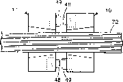
Further, the present invention also provides a kind of and has gone up the method for assembling at least one pair of optical conenctor positioning component (10) at continuous optical cable (72), and wherein connector positioning component (10) comprising:
A fiber orientation piece (12) is useful on optical fiber receiving plane (14) and the connector abutment surface (18) accepted from least one optical fiber of optical cable (16) on this locating piece;
First and second opening (44,46), these two openings are all gone up in connector abutment surface (18) and are formed; And
One place kick (62), this place kick remains in first opening, it is characterized in that,
This assembly further comprises first pair protrusion (48) adjacent with first opening and the second pair protrusion (49) adjacent with second opening, and these two pairs of protrusions are all from connector abutment surface projection; The size of second opening allow to accept slidably remain on with another connector positioning component of this optical connector pairing in place kick; Place kick remains between first pair of protrusion; And the size of first opening allows second pair of protrusion to insert, and the size of second opening allows first pair of protrusion to insert;
This method may further comprise the steps:
At least pair of connectors positioning component (10) is placed by arranging face-to-face;
Spacing part (71) is placed between the connector abutment surface (18) of at least one pair of connector positioning component (10);
Continuous optical cable (72) is lain on the connector positioning component (10), the optical fiber of each bar uncoated in the optical cable (72) is placed in each groove of locating slot (28) one by one;
Install and fix part (32), so that optical cable remains in the locating slot (28); And
Between connector positioning component (10), cut off optical cable (72).
Brief description of drawings
Fig. 1 is the skeleton view according to optical connector positioning component of the present invention.
Fig. 2 is the front view of positioning component among Fig. 1.
Fig. 3 a is according to the skeleton view of a pair of positioning component of the present invention before connection.
Fig. 3 b is the skeleton view that the positioning component shown in Fig. 3 a has been connected.
The assembling way that Fig. 4 a-d explanation assembles up many foundations positioning component of the present invention and multiple fiber cable.
Fig. 5 a-c explanation is in the terminal assembling way that a foundation positioning component of the present invention is installed of optical cable.
Fig. 6 is the skeleton view of positioning component in another embodiment of the invention.
Fig. 7 is the cut-open view along the 7-7 line intercepting of Fig. 6.
Fig. 8 is the cut-open view along the 8-8 line intercepting of Fig. 6.
Detailed description of the present invention
Fig. 1 illustrates the optical connector positioning component 10 according to one embodiment of the invention.This positioning component 10 has fiber orientation piece 12, this fiber orientation piece has leading edge 13, trailing edge 15, embeds the optical fiber receiving plane 14 of optical cable 16, with connector abutment surface 18, back 19 (in Fig. 3 a, providing), first side 21 and second side, 23 (not shown) of the connector abutment surface adjacency of another same connector positioning component.Optical cable 16 is made up of one or more simple optical fiber 17, and in preferential embodiment, every optical fiber suffers a ground by one of planar orientation substantially and places, to form optical fiber ribbon cable.
Optical fiber receiving plane 14 is included in the guide groove 20 that forms on the fiber orientation piece 12.Guide groove comprises first and second guide grooves locking lip 22 and 24, and at the bottom of guide groove 26. Locking lip 22,24 from leading edge 13 to trailing edge 15 outside shapes at an angle, to form trapezoidal guide groove.Specifically, along with locking lip 24 extends to trailing edge 15 from leading edge 13, it towards first side, 21 shapes at an angle.Along with locking lip 22 extends to trailing edge 15 from leading edge 13,23 shapes are at an angle towards the side for it.In addition, locking lip 22 and 24 from the top to bottom angled, to form a locking mechanism.Preferential is that lip limit 22b, 24b constituted bottom locking lip 22,24 was corresponded respectively to by lip limit, top 22a, 24a.The angle of inclination of locking lip 22,24 approximately is 30 °, thus bottom lip limit 22b, 24b respectively than lip limit, top 22a, 24a more near lateral margin 23,21.It should be noted that not breaking away from the spirit or scope of the present invention can use bigger or less pitch angle.
Form one or more locating slots 28 in guide groove bottom 26, to hold every optical fiber 17 from optical cable 16.Locating slot 28 is depicted as the V-type groove in preferential embodiment, still, under the condition that does not break away from spirit of the present invention and scope, also can use the groove of other cross sectional shapes, as rectangular channel, U type groove or semi-circular groove.Also form the guide groove 30 that holds optical cable shell in guide groove bottom 26.In normal running, optical fiber cable 16 is exposed every optical fiber 17 by the part peeling, so that put into locating slot 28.Peel one section optical cable shell off and optionally peel any coating around every optical fiber 17 off, the distance of being peeled off equals locating slot 28 length at least.By the guide groove 30 that holds optical cable shell is provided, every optical fiber 17 can keep the passage of substantially flat from start to finish on the whole width of fiber orientation piece 12.
In preferential embodiment, connector abutment surface 18 is the planes that are perpendicular to one another with optical fiber receiving plane 14.In order to reduce the light reflex reflection in the optical fiber, the vertical plane several years (preferentially being 6 ° to 9 °) that the plane of connector abutment surface 18 can stray fiber receiving plane 14, and also still favourable in some cases.Under the condition that does not break away from spirit and scope of the invention, the optical fiber receiving plane can depart from surface level up or down.In other words, the angle between optical fiber receiving plane 14 and the connector abutment surface can be in 81 ° to 99 ° scope.
Optical fiber of the present invention can be glass optical fiber single mode or multimode or plastic optical fiber.The glass optical fiber of multimode has the fine diameter of core in 50 to 100 micrometer ranges usually.Single-mode fiber has the fine diameter of less core.Because multimode optical fiber has the fine diameter of bigger core, thus it provide than single-mode fiber loose to plus tolerance.
Provide the swallow-tail form retaining element 32 of leading edge 34, trailing edge 36 and lateral margin 38,40,, especially every optical fiber 17 is fixed in the locating slot 28 so that optical cable 16 is fixed in the guide groove 20.On retaining element 32, provide assembling to pull and fail device 42, to help to install and fix part.In embodiments of the invention, swallow-tail form part 32 is trapezoidal, and leading edge 34 is shorter than trailing edge 36. Lateral margin 38 and 40 sizes are basic identical.The size and dimension of swallow-tail form retaining element 32 is consistent with guide groove 20 substantially, and its size allows it by being slidingly installed under guide groove locking lip 22 and 24.The width of retaining element 32 leading edges 34 is greater than the top lip limit 22a at leading edge 13 places and the distance between the 24a, less than the distance between bottom lip limit 22b and the 24b, and the width of trailing edge 36 is greater than the top lip limit 22a at trailing edge 15 places and the distance between the 24a, less than the distance between bottom lip limit 22b and the 24b.The height of retaining element 32 is less than the vertical range of self-conductance trench bottom 26 to lip limit, top 22a, 24a.The height of retaining element 32 approximately is 2mm, but under the condition that does not break away from spirit of the present invention and scope, can use bigger or less height.The size of retaining element 32 is to make leading edge 34 wideer than the guide groove 20 at leading edge 13 places, to guarantee that when retaining element 32 is installed in the guide groove 20 leading edge 34 is no more than leading edge 13 and forbids that it closely is connected with the connector of butt joint.
In preferential embodiment, fiber orientation piece 12 and retaining element 32 usefulness stupalith moldings form.But with plastics, glass, metal or any other known contiguous block made fiber orientation pieces 12 also is possible.In preferential embodiment,, fiber orientation piece 12 can be made rapidly and easily the unit as a whole by using mouldable material.For example, in preferential embodiment, can form locating slot 28 easily by method of molding, needn't working channel 20.
In Fig. 2, can see opening 44,46 in more detail.As shown in the figure, the shape of opening 44,46 is basic identical, but opening 46 revolves with respect to opening 44 and turn 90 degrees.The purpose of doing so just comes into focus after reading hereinafter.Opening 44 comprises cylindrical main receiving hole 54 and a pair of mesopore 56.Opening 46 comprises cylindrical main receiving hole 58 and a pair of mesopore 60.The diameter of cylindrical main receiving hole 54,58 is respectively d1 and d2, represents with the symbol 57 and 59 of band arrow respectively.Diameter d 1, d2 are corresponding with the spacing of cast molding protrusion 48,49 respectively.In the preferential embodiment of the present invention, the diameter d 2 of cylindrical hole 58 is a bit larger tham the diameter d 1 of cylindrical hole 54, so the distance between the protrusion 49 is a bit larger tham the distance between the protrusion 48.In preferential embodiment, the difference between diameter d 1 and the d2 is on several microns the order of magnitude.Accurate dimensions will depend on the type and the selected connector material of optical fiber.
As shown in Figure 2, mesopore 56 and cast molding protrusion 48 are basically around cylindrical main aperture 54.Similarly, cast molding protrusion 49 and mesopore 60 are basically around cylindrical main aperture 58.The shape of mesopore 56,60 is identical with cast molding protrusion 48,49 respectively in essence, and their degree of depth is enough to hold fully this protrusion.Importantly the degree of depth of mesopore 56,60 is the same with cast molding protrusion 48,49 at least, so that when two connectors linked to each other, their abutment surface 18 can contact with each other, thereby the optical fiber connector of installing on each connector is close together.
In order to insert the opening 44 between cast molding protrusion 48, provide precise positioning ball 62.It is for the optical fiber 17 in the locating slot 28 being aligned with optical fiber in another same connector, will further introducing below that precise positioning ball 62 is provided.Ball 62 is high-precision steel balls, but under the condition that does not break away from the spirit or scope of the present invention, also can be made the plastics such as tungsten carbide, pottery, other metals or liquid crystal polymer by other materials with ball precision.In preferential embodiment, ball 62 has the diameter of about 2mm, and diameter tolerance approximately be ± 0.5 micron.Importantly tolerance will change according to the material of place kick.Though margin tolerance is very important to proper handling of the present invention, will be appreciated that and under the condition that does not break away from the spirit or scope of the present invention, can use bigger or less diameter.
As mentioned above, the diameter d 1 of cylindrical main aperture 54 and protrusion 48 corresponding spacings all are slightly smaller than the diameter d 2 in hole 58.This is for ball 62 is closely remained in the hole 54.Cast molding protrusion 49 is designs like this, makes its spacing (d2) allow ball 62 to slide like a cork betwixt.If ball 62 is inserted into opening 46, it with not driving fit in wherein but drop out.The spacing tolerance of protrusion 48,49 depends on material therefor again.In preferential embodiment, adopt ceramic making fiber orientation piece, comprise protrusion.In this case, the spacing tolerance of protrusion 48 is approximately ± 2-3 micron (forming stationary fit with place kick), and the spacing tolerance of protrusion 49 approximately is ± and 0-2 micron (forming movingly) with place kick.If protrusion adopts plastic production, then the tolerance of protrusion 48 spacings be approximately ± 50 microns, for protrusion 49 also be approximately ± 50 microns.
Importantly should be noted that: in this embodiment, any specific degree of depth or position in ball 62 and the nonessential hole 54 between protrusion 48.Ball 62 can remain between the protrusion 48 but in the hole 54 outside, it also can half in hole 54, second half outside the hole, or be positioned at the hole fully, or any position betwixt, can not change the ability of aligning of the present invention.Shall also be noted that if desired, ball 62 can be bonded between the protrusion 48 under the prerequisite that does not break away from the spirit or scope of the present invention.In addition, should be noted that cylindrical hole 54 may have identical size fully with 58, so that two holes allow all place kick 62 to slide therein.Although this embodiment can not stop ball 62 to drop out from the hole when connector is still unassembled, this embodiment provides additional degrees of freedom when which hole decision embed with ball.
Fig. 3 a and two connector positioning components according to manufacturing of the present invention of 3b explanation are accurately assembled up.Illustrated connector positioning component 10 has by retaining element 32 and remains on optical fiber ribbon cable 16 in the locating slot 28.As shown in the figure, ball 62 has inserted the receiving hole 54 of two connector positioning components 10.The protrusion 48 of cast molding provides wringing fit, and ball 62 is remained in the hole 54.When the assembly connector positioning component, cast molding protrusion 48 is inserted in the mesopore 60, and protrusion 49 is inserted in the mesopore 56, and when protrusion 49 and ball 62 were inserted in the mesopore 56, the rounded internal surface 51 of protrusion 49 formed with ball 62 and is slidingly matched.Resemble when connecting Fig. 3 b, every the optical fiber 17 in the optical fiber ribbon cable 16 all accurately aligns, and the connector positioning component is restricted and can not multidirectionally moves.
The present invention also provides a kind of assembling automated method that makes connector positioning component 10 and optical fiber ribbon cable.This method is illustrated with Fig. 4 a-b.As shown in the figure, provide pair of connectors positioning component 10, and they are placed by arranging face-to-face.In preferential embodiment, provide spacing part 71 so that two connector positioning components 10 separate suitable distance.Spacing part 71 of the present invention is to use up the distance keeper of just throwing away, and it makes the spacing of positioning component be approximately 0.015 inch (0.038cm), but can select bigger or less distance under the condition that does not break away from the spirit or scope of the present invention.Distance keeper 71 is preferentially made of plastic, but also can use any other proper spacing material.Connector positioning component 10 can also be fixing on the spot by certain clamping institution under the prerequisite that does not break away from the spirit or scope of the present invention.
In case two connector positioning components are suitably separated, provide one section optical fiber ribbon cable 72 from continuous cylinder or similar source without interruption.Optical fiber ribbon cable is placed on the connector positioning component 10, makes every optical fiber be arranged in each locating slot 28, subsequently retaining element 32 is installed on two positioning components 10, optical fiber ribbon cable is close on the connector positioning component.At this moment, with optical fiber ribbon cable 72 sawed-off or cut-out in the position of distance keeper 71.At last, optical fiber connector is carried out necessary processing or smooth.Said method can also similarly be used for a connector is installed to the end of one section optical fiber ribbon cable.
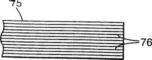
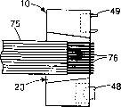
Connector positioning component of the present invention is very suitable for on-the-spot fast the installation.This artificial on-the-spot installation method is illustrated with Fig. 5 a-c.The technician at first need to determine the position of connector 10 along the length of optical fiber ribbon cable 75 at the scene.Then, cut off at this optical cable of naming a person for a particular job.Then, the insulating coating around the optical fiber is peeled off, to expose every optical fiber 76.Subsequently, every optical fiber is placed directly in locating slot 28 tops of positioning component.Next, with retaining element 32 sliding being inserted in the guide groove 20 of positioning component, optical fiber 76 is close in the locating slot 28.Optical fiber is stretched out the part of connector abutment surface 18 and excise, last, carry out necessary arrangement or smooth.
First alternate embodiment of the present invention is illustrated with Fig. 6.Fig. 6 illustrates a pair of positioning component that is about to combine 80.Positioning component 80 comprises fiber orientation piece 82, and optical fiber receiving surface 84 and connector abutment surface 86 are arranged on this locating piece, the connector abutment surface adjacency of this surface and another same connector.In this embodiment, fiber orientation piece 82 is molded with pottery or glass molds.On optical fiber receiving plane 84, form many locating slots 88, to keep every optical fiber from optical cable.By any known fixing means (such as adhesive tape or bonding agent) optical fiber is remained in the locating slot 88.
Chamfering 93 can be seen clearlyer in Fig. 7.As shown in the figure, chamfering 93 can be held half place kick of less than 94.Specifically, the depth d 3 (representing with 95) of chamfering 93 is less than the radius R (representing with 97) of place kick 94.In preferential alternate embodiment, the diameter d 4 (representing with 99) of place kick is approximately 2mm, so its radius is approximately 1mm.Therefore, depth d 3 (95) is less than about 1mm, in about 0.5 to 0.7mm scope.Ball 94 just imports bonding agent by after-opening 92b, so that ball 94 is fixed in the opening 92 in case seat advances chamfering 93.It should be noted that presumable positioning component does not run through through hole 90a, the 92a of positioning component length.Bonding agent can directly be coated on the chamfering 93, subsequently ball 94 is put in, and needs only coating adhesive equably, and place kick 94 just can accurately be sitting in the chamfering 93.
Referring now to Fig. 8, illustrate in greater detail opening 90.The size of opening 90 is a bit larger tham the diameter d 4 shown in 99.This allows place kick 94 to put into opening 90 slidably.As shown in Figure 8, after-opening 90b and through hole 90a are greater than opening 90.This is the area that needs machining in order to reduce.Machining precision is the key that optical fiber is aligned, so the allowance for finish of opening 90 is very strict, on 4 or 5 microns the order of magnitude.Because through hole 90a and after-opening 90b are greater than opening 90, so lathe only need be processed less surface area.
The precise positioning ball 94 that is fit to embed opening 92 is provided.Ball 94 provides for every the optical fiber that accurately aligns pair of connectors positioning component 80, also accurately align successively in the optical cable that is fixed on this positioning component.For the application of using single-mode fiber, ball 94 is steel balls of the precision of tolerance in ± 0.5 micrometer range, and for the application of using multimode optical fiber, tolerance is in ± 2 microns scope.Under the prerequisite that does not break away from the spirit or scope of the present invention, ball 94 also can be made with the other materials with ball bearing precision, the plastics such as tungsten carbide, pottery, other metals or liquid crystal polymer.As mentioned above, ball 94 is bonded in the opening 92.Can be bonding with bonding agent or the realization of low melting point ceramic seal glass, wherein said seal glass can bond to fiber orientation piece 80 pottery or glass when cooling subsequently in the high temperature current downflow of appropriateness with place kick 94.Under the prerequisite that does not break away from the spirit or scope of the present invention, also can use other bonding agent.
Claims (14)
1. an optical connector positioning component (80), this assembly comprises:
A fiber orientation piece (82) is useful on optical fiber receiving plane (84) and the connector abutment surface (86) accepted from least one optical fiber of optical cable (16) on this locating piece;
First and second opening (92,90), these two openings are all gone up in connector abutment surface (86) and are formed, and first opening (92) wherein has d
3The degree of depth, second opening (90) is a tubular; And
One place kick (94), its radius are R, and this place kick remains in first opening, wherein R>d
3, the size of second opening (90) is greater than the diameter of place kick (94).
2. connector positioning component according to claim 1, wherein said optical fiber receiving plane comprises at least one locating slot (28), to keep at least one optical fiber from optical cable.
3. connector positioning component according to claim 1, wherein the size of second opening allow to accept slidably remain on with another connector positioning component of this optical connector pairing in place kick.
4. connector positioning component according to claim 1, wherein place kick is close to cooperate and is fixed in first opening.
5. connector positioning component according to claim 1, wherein this place kick is bonded in first opening.
6. connector positioning component according to claim 1, wherein first and second openings link to each other with first and second through holes respectively, and first and second through hole runs through the width of fiber orientation piece.
7. an optical connector positioning component (10) comprising:
A fiber orientation piece (12) is useful on optical fiber receiving plane (14) and the connector abutment surface (18) accepted from least one optical fiber of optical cable (16) on this locating piece;
First and second opening (44,46), these two openings are all gone up in connector abutment surface (18) and are formed; And
One place kick (62), this place kick remains in first opening, it is characterized in that,
This assembly further comprises first pair protrusion (48) adjacent with first opening and the second pair protrusion (49) adjacent with second opening, and these two pairs of protrusions are all from connector abutment surface projection; The size of second opening allow to accept slidably remain on with another connector positioning component of this optical connector pairing in place kick; Place kick remains between first pair of protrusion; And the size of first opening allows second pair of protrusion to insert, and the size of second opening allows first pair of protrusion to insert.
8. connector positioning component according to claim 7, wherein place kick and second pair of protrusion form and are slidingly matched.
9. optical connector positioning component according to claim 7 (10), this assembly comprises:
Guide groove (20), this guide groove forms on the optical fiber receiving plane;
At least one locating slot (28), this locating slot form in guide groove (20); And
Retaining element (32), the size of this retaining element are fixed in the guide groove (20) it, so that at least one optical fiber is fixed at least one locating slot (28).
10. connector positioning component according to claim 9, guide groove wherein comprises guide groove surface (26) and the first locking lip and the second locking lip (22,24), and locking lip (22,24) comprise lip limit, top and lip limit, bottom (22a again, 24a, 22b, 24b), wherein top lip limit distance apart is first distance, lip limit, bottom distance apart is a second distance, lip limit, top and guide groove surface (26) distance apart are the 3rd distance, and this locking lip slopes inwardly to lip limit, bottom from lip limit, top, so that the distance of first between the lip limit, top is less than the second distance between the lip limit, bottom.
11. connector positioning component according to claim 10, wherein the thickness of this retaining element is less than the 3rd distance on lip limit, top to guide groove surface.
12. connector positioning component according to claim 11, wherein when retaining element inserted guide groove, this retaining element remained in the guide groove by the first and second locking lips.
13. connector positioning component according to claim 7, wherein this connector abutment surface and optical fiber receiving plane shape at an angle, this angle is in 81 ° of-99 ° of scopes.
14. a method of upward assembling at least one pair of optical conenctor positioning component (10) at continuous optical cable (72), wherein connector positioning component (10) comprising:
A fiber orientation piece (12) is useful on optical fiber receiving plane (14) and the connector abutment surface (18) accepted from least one optical fiber of optical cable (16) on this locating piece;
First and second opening (44,46), these two openings are all gone up in connector abutment surface (18) and are formed; And
One place kick (62), this place kick remains in first opening, it is characterized in that,
This assembly further comprises first pair protrusion (48) adjacent with first opening and the second pair protrusion (49) adjacent with second opening, and these two pairs of protrusions are all from connector abutment surface projection; The size of second opening allow to accept slidably remain on with another connector positioning component of this optical connector pairing in place kick; Place kick remains between first pair of protrusion; And the size of first opening allows second pair of protrusion to insert, and the size of second opening allows first pair of protrusion to insert;
This method may further comprise the steps:
At least pair of connectors positioning component (10) is placed by arranging face-to-face;
Spacing part (71) is placed between the connector abutment surface (18) of at least one pair of connector positioning component (10);
Continuous optical cable (72) is lain on the connector positioning component (10), the optical fiber of each bar uncoated in the optical cable (72) is placed in each groove of locating slot (28) one by one;
Install and fix part (32), so that optical cable remains in the locating slot (28); And
Between connector positioning component (10), cut off optical cable (72).
Applications Claiming Priority (2)
| Application Number | Priority Date | Filing Date | Title |
|---|---|---|---|
| US08/614,412 | 1996-03-12 | ||
| US08/614,412 US5778123A (en) | 1996-03-12 | 1996-03-12 | Alignment assembly for multifiber or single fiber optical cable connector |
Publications (2)
| Publication Number | Publication Date |
|---|---|
| CN1214122A CN1214122A (en) | 1999-04-14 |
| CN1129016C true CN1129016C (en) | 2003-11-26 |
Family
ID=24461155
Family Applications (1)
| Application Number | Title | Priority Date | Filing Date |
|---|---|---|---|
| CN96180202A Expired - Fee Related CN1129016C (en) | 1996-03-12 | 1996-10-07 | Alignment assembly for multifiber or single fiber optical cable connector |
Country Status (9)
| Country | Link |
|---|---|
| US (2) | US5778123A (en) |
| EP (3) | EP0886797B1 (en) |
| JP (1) | JP2000505208A (en) |
| KR (1) | KR19990087648A (en) |
| CN (1) | CN1129016C (en) |
| DE (1) | DE69618668T2 (en) |
| HK (1) | HK1019169A1 (en) |
| TW (1) | TW381186B (en) |
| WO (1) | WO1997034179A1 (en) |
Cited By (2)
| Publication number | Priority date | Publication date | Assignee | Title |
|---|---|---|---|---|
| TWI422887B (en) * | 2005-09-12 | 2014-01-11 | Stratos Int Inc | Opto-electric connector |
| TWI561877B (en) * | 2012-03-23 | 2016-12-11 | Hon Hai Prec Ind Co Ltd | Photoelectric transmitting module and optical fiber connector thereof |
Families Citing this family (67)
| Publication number | Priority date | Publication date | Assignee | Title |
|---|---|---|---|---|
| US6805493B2 (en) | 1996-03-12 | 2004-10-19 | 3M Innovative Properties Company | Optical connector assembly using partial large diameter alignment features |
| US5920670A (en) * | 1996-06-07 | 1999-07-06 | 3M Innovative Properties Company | Multiple alignment connector ferrule |
| US5940562A (en) * | 1996-03-12 | 1999-08-17 | Minnesota Mining And Manufacturing Company | Stubless optoelectronic device receptacle |
| US6318902B1 (en) | 1996-03-12 | 2001-11-20 | 3M Innovative Properties Company | Optical connector assembly using partial large diameter alignment features |
| US5778123A (en) * | 1996-03-12 | 1998-07-07 | Minnesota Mining And Manufacturing Company | Alignment assembly for multifiber or single fiber optical cable connector |
| CA2262351A1 (en) * | 1998-02-24 | 1999-08-24 | Jds Fitel Inc. | Tunable multiple fiber optical connector |
| JPH11344640A (en) * | 1998-03-31 | 1999-12-14 | Ngk Insulators Ltd | Glass substrate and its two-stage forming method |
| JPH11281823A (en) * | 1998-03-31 | 1999-10-15 | Oki Electric Ind Co Ltd | Arraying method for optical fiber and optical fiber array device |
| CA2336388C (en) * | 1998-07-02 | 2008-09-09 | Tyco Electronics Logistics Ag | Ferrule for a pluggable optical connection |
| FR2786881B1 (en) * | 1998-12-03 | 2002-08-16 | Socapex Amphenol | HERMAPHRODITE OPTICAL CONNECTOR |
| US6332052B1 (en) * | 2000-02-28 | 2001-12-18 | Corning Cable Systems Llc | Optical fiber ribbon cables with controlled bending behavior |
| US6832016B2 (en) * | 2000-04-13 | 2004-12-14 | Shipley Company, L.L.C. | Fiber array switch having micromachined front face with roller balls |
| US6842552B1 (en) | 2000-04-13 | 2005-01-11 | Shipley Company, L.L.C. | Optical waveguide switch |
| US6798933B2 (en) * | 2000-04-14 | 2004-09-28 | Shipley Company, L.L.C. | Fiber optic array switch |
| US6826324B2 (en) * | 2000-04-13 | 2004-11-30 | Shipley Company, L.L.C. | Optical waveguide switch |
| US6633691B2 (en) * | 2000-05-02 | 2003-10-14 | Shipley Company, L.L.C. | Optical waveguide switch having stepped waveguide holding member |
| US6748131B2 (en) * | 2000-05-19 | 2004-06-08 | Shipley Company, L.L.C. | Optical waveguide devices and methods of fabricating the same |
| US6434315B1 (en) * | 2000-06-23 | 2002-08-13 | Molex Incorporated | Fiber optic connector |
| US6434316B1 (en) * | 2000-06-23 | 2002-08-13 | Molex Incorporated | Fiber optic connector |
| US6870981B2 (en) | 2000-08-24 | 2005-03-22 | Shipley Company, L.L.C. | Optical switch and method for making |
| US6853764B2 (en) * | 2000-08-28 | 2005-02-08 | Shipley Company, L.L.C. | Optical switch assembly and method for making |
| US6798968B2 (en) * | 2000-09-21 | 2004-09-28 | Shipley Company, L.L.C. | Fiber array with support post |
| US6526205B1 (en) * | 2000-10-13 | 2003-02-25 | Agilent Technologies, Inc. | Method and apparatus for the passive alignment of optical components |
| US6520686B1 (en) | 2000-11-09 | 2003-02-18 | Teradyne, Inc. | Methods and apparatus for forming a fiber optic connection |
| US6799897B2 (en) | 2000-11-16 | 2004-10-05 | Shipley Company, L.L.C. | Optical connector system |
| US6810162B2 (en) * | 2000-12-20 | 2004-10-26 | Shipley Company, L.L.C. | Optical switch assembly with flex plate and method for making |
| US6527457B2 (en) | 2001-02-01 | 2003-03-04 | International Business Machines Corporation | Optical fiber guide module and a method for making the same |
| JP2002328251A (en) * | 2001-02-28 | 2002-11-15 | Asahi Glass Co Ltd | Method for coupling resin optical fibers |
| US6623177B1 (en) | 2001-07-09 | 2003-09-23 | Emc Corporation | Systems and methods for providing fiber optic communications between circuit boards |
| US20030086661A1 (en) * | 2001-11-02 | 2003-05-08 | Boudreau Robert A. | Silicon waferboard |
| US7410304B2 (en) * | 2001-11-08 | 2008-08-12 | Rohm And Haas Electronic Materials Llc | Optical fiber right angle transition |
| US6839935B2 (en) * | 2002-05-29 | 2005-01-11 | Teradyne, Inc. | Methods and apparatus for cleaning optical connectors |
| US6957920B2 (en) | 2002-06-24 | 2005-10-25 | Corning Cable Systems Llc | Ferrule assembly having highly protruding optical fibers and an associated fabrication method |
| US6762941B2 (en) | 2002-07-15 | 2004-07-13 | Teradyne, Inc. | Techniques for connecting a set of connecting elements using an improved latching apparatus |
| US6832858B2 (en) * | 2002-09-13 | 2004-12-21 | Teradyne, Inc. | Techniques for forming fiber optic connections in a modularized manner |
| US7042562B2 (en) * | 2002-12-26 | 2006-05-09 | Amphenol Corp. | Systems and methods for inspecting an optical interface |
| JP2005352453A (en) * | 2004-05-12 | 2005-12-22 | Nec Corp | Optical fiber component, optical waveguide module, and manufacturing method |
| KR101119780B1 (en) * | 2005-06-30 | 2012-03-23 | 엘지디스플레이 주식회사 | Plasma enhanced chemical vapor deposition device |
| EP1904880A1 (en) * | 2005-07-15 | 2008-04-02 | Diamond S.A. | Optical multi-thread plug connection |
| US7515782B2 (en) * | 2006-03-17 | 2009-04-07 | Zhang Boying B | Two-channel, dual-mode, fiber optic rotary joint |
| JP4901654B2 (en) * | 2007-09-03 | 2012-03-21 | 株式会社フジクラ | Optical connector |
| US20090196563A1 (en) * | 2008-02-01 | 2009-08-06 | Mullsteff David M | Multi-Fiber Optical Patch Cord Breakout Assembly |
| US8571366B2 (en) * | 2008-05-09 | 2013-10-29 | Hewlett-Packard Development Company, L.P. | Proximity free space optical interconnect |
| US20100067852A1 (en) * | 2008-09-18 | 2010-03-18 | International Business Machines Corporation | Method for assembling a furrule for an optical wave guide connector, ferrule, wave guide ribbon and tool for assembling the ferrule |
| US8580162B2 (en) * | 2009-03-17 | 2013-11-12 | Adc Telecommunications, Inc. | Method of directly molding ferrule on fiber optic cable |
| US8408816B2 (en) | 2010-03-18 | 2013-04-02 | Fujikura Ltd. | Optical connector |
| US8529138B2 (en) | 2010-07-15 | 2013-09-10 | Tyco Electronics Corporation | Ferrule for optical transports |
| US9529159B2 (en) * | 2010-07-30 | 2016-12-27 | Corning Optical Communications LLC | Ferrules with complementary mating geometry and related fiber optic connectors |
| US10401572B2 (en) * | 2010-07-30 | 2019-09-03 | Corning Optical Communications, Llc | Fiber optic connectors including ferrules with complementary mating geometry and related fiber optic connectors |
| EP2598926A1 (en) * | 2010-07-30 | 2013-06-05 | Corning Cable Systems LLC | Ferrules with complimentary mating geometry and related fiber optic connectors |
| US8585300B2 (en) * | 2011-02-09 | 2013-11-19 | Tyco Electronics Nederland Bv | Ferrule with alignment pin channels |
| TWM450737U (en) * | 2011-06-14 | 2013-04-11 | Molex Inc | Optical fiber assembly |
| US10215926B2 (en) | 2011-12-14 | 2019-02-26 | Commscope Technologies Llc | Multi-fiber fiber optic connection system with flexible, insertable pins |
| CA2869678A1 (en) * | 2012-04-11 | 2013-10-17 | Nanoprecision Products, Inc. | Hermetic optical fiber alignment assembly having integrated optical element |
| US9897764B2 (en) | 2012-09-28 | 2018-02-20 | Commscope Technologies Llc | Molded ferrules for optical fibers |
| JP2014106409A (en) * | 2012-11-28 | 2014-06-09 | International Business Maschines Corporation | Connector for multilayered optical waveguide |
| CN104678504B (en) * | 2013-11-30 | 2018-07-27 | 内蒙古炎林通讯技术有限公司 | Optical fiber connector |
| JP6459334B2 (en) * | 2014-09-18 | 2019-01-30 | 住友電気工業株式会社 | Ferrule and optical connection structure |
| WO2016087449A1 (en) | 2014-12-01 | 2016-06-09 | Commscope Asia Holdings B.V. | Multi-fiber optic connector with pivotally-aligned ferrule |
| US10203457B2 (en) | 2015-06-19 | 2019-02-12 | Commscope Technologies Llc | Fiber optic connector ferrule with improved alignment mechanism |
| WO2017066037A1 (en) | 2015-10-12 | 2017-04-20 | 3M Innovative Properties Company | Optical ferrules |
| US10921522B2 (en) * | 2017-04-04 | 2021-02-16 | Tdk Corporation | Optical fiber member and optical fiber holder |
| CN107577014B (en) * | 2017-09-11 | 2019-06-28 | 武汉福地科技有限公司 | A kind of fiber array connection equipment with transceiver function |
| KR20210145184A (en) | 2019-03-20 | 2021-12-01 | 티코나 엘엘씨 | Actuator assembly for camera module |
| JP2022524720A (en) | 2019-03-20 | 2022-05-10 | ティコナ・エルエルシー | Polymer composition for use in camera modules |
| WO2020235041A1 (en) * | 2019-05-22 | 2020-11-26 | 日本電信電話株式会社 | Waveguide connection structure, waveguide chip, connector, method for manufacturing waveguide connection component, and method for connecting wavegude |
| US10942316B1 (en) * | 2019-10-31 | 2021-03-09 | Alliance Fiber Optic Products, Inc. | FAU connectors and assemblies employing pin-to-pin alignment |
Citations (3)
| Publication number | Priority date | Publication date | Assignee | Title |
|---|---|---|---|---|
| DE3409641A1 (en) * | 1984-03-16 | 1985-09-19 | Standard Elektrik Lorenz Ag, 7000 Stuttgart | Demountable connection for optical fibres |
| US5315678A (en) * | 1992-03-30 | 1994-05-24 | Nippon Telegraph & Telephone Corporation | Optical fiber connector |
| US5430819A (en) * | 1993-12-21 | 1995-07-04 | At&T Corp. | Multiple optical fiber connector and method of making same |
Family Cites Families (26)
| Publication number | Priority date | Publication date | Assignee | Title |
|---|---|---|---|---|
| US3871935A (en) * | 1974-03-14 | 1975-03-18 | Bell Telephone Labor Inc | Method of encapsulating and terminating the fibers of an optical fiber ribbon |
| US4037902A (en) * | 1976-03-16 | 1977-07-26 | Tesco Engineering Company | Hermaphroditic multiple connector plug |
| US4094580A (en) * | 1976-12-27 | 1978-06-13 | Bell Telephone Laboratories, Incorporated | Hermaphrodite optical fiber connector |
| US4116532A (en) * | 1977-01-05 | 1978-09-26 | Bell Telephone Laboratories, Incorporated | Fiber positioning and connection method and apparatus |
| US4087155A (en) * | 1977-03-23 | 1978-05-02 | International Telephone & Telegraph Corporation | Single optical fiber connector utilizing spherical alignment elements |
| GB1600272A (en) * | 1977-05-02 | 1981-10-14 | Plessey Co Ltd | Optical fibre connectors |
| US4279466A (en) * | 1978-02-21 | 1981-07-21 | Bunker Ramo Corporation | Hermaphroditic fiber optic connector |
| US4184742A (en) * | 1978-10-26 | 1980-01-22 | International Telephone And Telegraph Corporation | Hermaphroditic fiber optic connector |
| US4712861A (en) * | 1985-02-07 | 1987-12-15 | Northern Telecom Limited | Two-channel hermaphroditic fiber connector |
| US4737118A (en) * | 1985-12-20 | 1988-04-12 | Amp Incorporated | Hermaphroditic flat cable connector |
| US4953944A (en) * | 1988-10-12 | 1990-09-04 | Hughes Aircraft Company | Multi-channel hermaphroditic lens type fiber optic connector |
| US5183409A (en) * | 1991-04-15 | 1993-02-02 | Eric Clever | Hermaphroditic multiple contact connector |
| US5214730A (en) * | 1991-05-13 | 1993-05-25 | Nippon Telegraph And Telephone Corporation | Multifiber optical connector plug with low reflection and low insertion loss |
| US5121457A (en) * | 1991-05-21 | 1992-06-09 | Gte Laboratories Incorporated | Method for coupling laser array to optical fiber array |
| US5123073A (en) * | 1991-05-31 | 1992-06-16 | At&T Bell Laboratories | Precision optical fiber connector |
| AU649162B2 (en) * | 1991-08-17 | 1994-05-12 | Nippon Telegraph & Telephone Corporation | Optical connector |
| US5151964A (en) * | 1991-09-06 | 1992-09-29 | Minnesota Mining And Manufacturing Company | Wedge-actuated multiple optical fiber splice |
| JPH0743455B2 (en) * | 1991-09-24 | 1995-05-15 | 株式会社精工技研 | Ribbon fiber optic connector |
| US5257332A (en) * | 1992-09-04 | 1993-10-26 | At&T Bell Laboratories | Optical fiber expanded beam coupler |
| CA2114689C (en) * | 1993-02-02 | 2000-03-28 | Makoto Honjo | Optical connector and adhesive therefor |
| JPH06337328A (en) * | 1993-03-29 | 1994-12-06 | Sumitomo Electric Ind Ltd | Optical connector |
| JPH0720340A (en) * | 1993-06-28 | 1995-01-24 | Nippon Telegr & Teleph Corp <Ntt> | Optical fiber block array and its production |
| US5333225A (en) * | 1993-08-03 | 1994-07-26 | International Business Machines Corporation | Substrate-embedded pluggable receptacles for connecting clustered optical cables to a module |
| JP3256922B2 (en) * | 1994-10-13 | 2002-02-18 | 古河電気工業株式会社 | Optical connector |
| US5727097A (en) * | 1996-06-07 | 1998-03-10 | Minnesota Mining And Manufacturing Company | Pull-proof fiber optic array connector |
| US5778123A (en) * | 1996-03-12 | 1998-07-07 | Minnesota Mining And Manufacturing Company | Alignment assembly for multifiber or single fiber optical cable connector |
-
1996
- 1996-03-12 US US08/614,412 patent/US5778123A/en not_active Expired - Fee Related
- 1996-10-07 CN CN96180202A patent/CN1129016C/en not_active Expired - Fee Related
- 1996-10-07 WO PCT/US1996/016052 patent/WO1997034179A1/en not_active Application Discontinuation
- 1996-10-07 DE DE69618668T patent/DE69618668T2/en not_active Expired - Fee Related
- 1996-10-07 EP EP96934091A patent/EP0886797B1/en not_active Expired - Lifetime
- 1996-10-07 EP EP00111351A patent/EP1028335A3/en not_active Withdrawn
- 1996-10-07 KR KR1019980707105A patent/KR19990087648A/en not_active Application Discontinuation
- 1996-10-07 JP JP9511495A patent/JP2000505208A/en not_active Withdrawn
- 1996-10-07 EP EP00111353A patent/EP1028336A3/en not_active Withdrawn
-
1997
- 1997-02-14 TW TW086101690A patent/TW381186B/en active
- 1997-10-20 US US08/953,950 patent/US5845028A/en not_active Expired - Fee Related
-
1999
- 1999-10-04 HK HK99104305A patent/HK1019169A1/en not_active IP Right Cessation
Patent Citations (3)
| Publication number | Priority date | Publication date | Assignee | Title |
|---|---|---|---|---|
| DE3409641A1 (en) * | 1984-03-16 | 1985-09-19 | Standard Elektrik Lorenz Ag, 7000 Stuttgart | Demountable connection for optical fibres |
| US5315678A (en) * | 1992-03-30 | 1994-05-24 | Nippon Telegraph & Telephone Corporation | Optical fiber connector |
| US5430819A (en) * | 1993-12-21 | 1995-07-04 | At&T Corp. | Multiple optical fiber connector and method of making same |
Cited By (2)
| Publication number | Priority date | Publication date | Assignee | Title |
|---|---|---|---|---|
| TWI422887B (en) * | 2005-09-12 | 2014-01-11 | Stratos Int Inc | Opto-electric connector |
| TWI561877B (en) * | 2012-03-23 | 2016-12-11 | Hon Hai Prec Ind Co Ltd | Photoelectric transmitting module and optical fiber connector thereof |
Also Published As
| Publication number | Publication date |
|---|---|
| EP0886797B1 (en) | 2002-01-02 |
| EP0886797A1 (en) | 1998-12-30 |
| DE69618668D1 (en) | 2002-02-28 |
| EP1028335A2 (en) | 2000-08-16 |
| US5845028A (en) | 1998-12-01 |
| JP2000505208A (en) | 2000-04-25 |
| KR19990087648A (en) | 1999-12-27 |
| US5778123A (en) | 1998-07-07 |
| EP1028336A2 (en) | 2000-08-16 |
| WO1997034179A1 (en) | 1997-09-18 |
| EP1028336A3 (en) | 2000-09-06 |
| TW381186B (en) | 2000-02-01 |
| HK1019169A1 (en) | 2000-01-14 |
| EP1028335A3 (en) | 2000-09-06 |
| DE69618668T2 (en) | 2002-08-14 |
| CN1214122A (en) | 1999-04-14 |
Similar Documents
| Publication | Publication Date | Title |
|---|---|---|
| CN1129016C (en) | Alignment assembly for multifiber or single fiber optical cable connector | |
| CN1129015C (en) | Fixture for fabricating fiber optic connector ferrule | |
| CN103597393B (en) | The thimble assembly of laterally inserted optical fiber | |
| CN1192268C (en) | Optical fiber connector | |
| CN101806940B (en) | Optical fiber field connector | |
| CN1134688C (en) | Method for making optical fibre connector sleeve | |
| US4738508A (en) | Terminated optical fiber and methods of making | |
| CN1091523C (en) | Optical connector | |
| CN104412143B (en) | Fiber optic connector ferrule with curved outer alignment surface | |
| CN1019148B (en) | Optical fiber connectors and method of making | |
| EP0327267B1 (en) | Optical fiber connector and methods of making | |
| CN103562767A (en) | Multifiber connectors for multicore optical fiber cables | |
| CN1220015A (en) | Optoelectronic device receptacle and method of making same | |
| CN1500220A (en) | Low-loss intermatable forrules for optical fibers and method of fabrication thereof | |
| JP2013238692A (en) | Method for manufacturing multi-core fiber connector and device for rotating multi-core fiber | |
| CN1373376A (en) | Method for connecting plastic optical fibre | |
| CN104635304A (en) | Optical fiber connector insert and manufacturing method thereof and optical fiber connector | |
| CN1134686C (en) | Optical-fiber connector hoop | |
| CN1735825A (en) | Device having multiple optical fibers | |
| CN1209559A (en) | Alignment system in connector hoop of optical cable | |
| CN1879044A (en) | Optical fibre connector | |
| CN1412585A (en) | Optical coupling module | |
| CN1508587A (en) | Mosaic lens in optical system | |
| US7274845B2 (en) | Low-cost method and apparatus for establishing fiber optic connections | |
| CN213717980U (en) | Light path display easy to observe |
Legal Events
| Date | Code | Title | Description |
|---|---|---|---|
| C06 | Publication | ||
| PB01 | Publication | ||
| C10 | Entry into substantive examination | ||
| SE01 | Entry into force of request for substantive examination | ||
| C14 | Grant of patent or utility model | ||
| GR01 | Patent grant | ||
| C19 | Lapse of patent right due to non-payment of the annual fee | ||
| CF01 | Termination of patent right due to non-payment of annual fee |