CN112889194B - Power distribution device, power distribution method, and computer program - Google Patents
Power distribution device, power distribution method, and computer program Download PDFInfo
- Publication number
- CN112889194B CN112889194B CN201980063488.3A CN201980063488A CN112889194B CN 112889194 B CN112889194 B CN 112889194B CN 201980063488 A CN201980063488 A CN 201980063488A CN 112889194 B CN112889194 B CN 112889194B
- Authority
- CN
- China
- Prior art keywords
- switches
- current
- equal
- temperature
- electric wire
- Prior art date
- Legal status (The legal status is an assumption and is not a legal conclusion. Google has not performed a legal analysis and makes no representation as to the accuracy of the status listed.)
- Active
Links
Images


Classifications
-
- H—ELECTRICITY
- H02—GENERATION; CONVERSION OR DISTRIBUTION OF ELECTRIC POWER
- H02H—EMERGENCY PROTECTIVE CIRCUIT ARRANGEMENTS
- H02H5/00—Emergency protective circuit arrangements for automatic disconnection directly responsive to an undesired change from normal non-electric working conditions with or without subsequent reconnection
- H02H5/04—Emergency protective circuit arrangements for automatic disconnection directly responsive to an undesired change from normal non-electric working conditions with or without subsequent reconnection responsive to abnormal temperature
-
- H—ELECTRICITY
- H02—GENERATION; CONVERSION OR DISTRIBUTION OF ELECTRIC POWER
- H02H—EMERGENCY PROTECTIVE CIRCUIT ARRANGEMENTS
- H02H3/00—Emergency protective circuit arrangements for automatic disconnection directly responsive to an undesired change from normal electric working condition with or without subsequent reconnection ; integrated protection
- H02H3/08—Emergency protective circuit arrangements for automatic disconnection directly responsive to an undesired change from normal electric working condition with or without subsequent reconnection ; integrated protection responsive to excess current
- H02H3/087—Emergency protective circuit arrangements for automatic disconnection directly responsive to an undesired change from normal electric working condition with or without subsequent reconnection ; integrated protection responsive to excess current for dc applications
-
- G—PHYSICS
- G01—MEASURING; TESTING
- G01R—MEASURING ELECTRIC VARIABLES; MEASURING MAGNETIC VARIABLES
- G01R19/00—Arrangements for measuring currents or voltages or for indicating presence or sign thereof
- G01R19/165—Indicating that current or voltage is either above or below a predetermined value or within or outside a predetermined range of values
- G01R19/16533—Indicating that current or voltage is either above or below a predetermined value or within or outside a predetermined range of values characterised by the application
- G01R19/16538—Indicating that current or voltage is either above or below a predetermined value or within or outside a predetermined range of values characterised by the application in AC or DC supplies
-
- H—ELECTRICITY
- H01—ELECTRIC ELEMENTS
- H01H—ELECTRIC SWITCHES; RELAYS; SELECTORS; EMERGENCY PROTECTIVE DEVICES
- H01H85/00—Protective devices in which the current flows through a part of fusible material and this current is interrupted by displacement of the fusible material when this current becomes excessive
- H01H85/02—Details
- H01H85/04—Fuses, i.e. expendable parts of the protective device, e.g. cartridges
- H01H85/05—Component parts thereof
- H01H85/055—Fusible members
- H01H85/08—Fusible members characterised by the shape or form of the fusible member
-
- H—ELECTRICITY
- H02—GENERATION; CONVERSION OR DISTRIBUTION OF ELECTRIC POWER
- H02H—EMERGENCY PROTECTIVE CIRCUIT ARRANGEMENTS
- H02H3/00—Emergency protective circuit arrangements for automatic disconnection directly responsive to an undesired change from normal electric working condition with or without subsequent reconnection ; integrated protection
- H02H3/08—Emergency protective circuit arrangements for automatic disconnection directly responsive to an undesired change from normal electric working condition with or without subsequent reconnection ; integrated protection responsive to excess current
- H02H3/085—Emergency protective circuit arrangements for automatic disconnection directly responsive to an undesired change from normal electric working condition with or without subsequent reconnection ; integrated protection responsive to excess current making use of a thermal sensor, e.g. thermistor, heated by the excess current
-
- H—ELECTRICITY
- H02—GENERATION; CONVERSION OR DISTRIBUTION OF ELECTRIC POWER
- H02H—EMERGENCY PROTECTIVE CIRCUIT ARRANGEMENTS
- H02H5/00—Emergency protective circuit arrangements for automatic disconnection directly responsive to an undesired change from normal non-electric working conditions with or without subsequent reconnection
- H02H5/04—Emergency protective circuit arrangements for automatic disconnection directly responsive to an undesired change from normal non-electric working conditions with or without subsequent reconnection responsive to abnormal temperature
- H02H5/041—Emergency protective circuit arrangements for automatic disconnection directly responsive to an undesired change from normal non-electric working conditions with or without subsequent reconnection responsive to abnormal temperature additionally responsive to excess current
-
- H—ELECTRICITY
- H02—GENERATION; CONVERSION OR DISTRIBUTION OF ELECTRIC POWER
- H02H—EMERGENCY PROTECTIVE CIRCUIT ARRANGEMENTS
- H02H6/00—Emergency protective circuit arrangements responsive to undesired changes from normal non-electric working conditions using simulators of the apparatus being protected, e.g. using thermal images
-
- H—ELECTRICITY
- H02—GENERATION; CONVERSION OR DISTRIBUTION OF ELECTRIC POWER
- H02J—CIRCUIT ARRANGEMENTS OR SYSTEMS FOR SUPPLYING OR DISTRIBUTING ELECTRIC POWER; SYSTEMS FOR STORING ELECTRIC ENERGY
- H02J7/00—Circuit arrangements for charging or depolarising batteries or for supplying loads from batteries
-
- H—ELECTRICITY
- H03—ELECTRONIC CIRCUITRY
- H03K—PULSE TECHNIQUE
- H03K17/00—Electronic switching or gating, i.e. not by contact-making and –breaking
- H03K17/51—Electronic switching or gating, i.e. not by contact-making and –breaking characterised by the components used
- H03K17/56—Electronic switching or gating, i.e. not by contact-making and –breaking characterised by the components used by the use, as active elements, of semiconductor devices
- H03K17/687—Electronic switching or gating, i.e. not by contact-making and –breaking characterised by the components used by the use, as active elements, of semiconductor devices the devices being field-effect transistors
Abstract
In the power distribution device, a current detection circuit detects a current value of a current flowing in an electric wire. When the switch is turned on, the microcomputer determines whether or not a predetermined condition is satisfied based on the current value detected by the current detection circuit. When the microcomputer determines that the predetermined condition is satisfied, the drive circuit switches the switch off.
Description
Technical Field
The present disclosure relates to a power distribution apparatus, a power distribution method, and a computer program.
The present application claims priority to japanese application No. 2018-196859 filed on 2018, 10, 18 and cites the entire contents of the description in said japanese application.
Background
A vehicle is equipped with a power distribution device that distributes power supplied from a dc power supply via electric wires to a plurality of loads via a plurality of supply paths (see patent literature 1). The power distribution device is provided with a fusing element that fuses when a current equal to or greater than a fusing threshold value continues to flow. The current flows from the positive electrode of the dc power supply to the fuse element and the electric wire in this order. The current output from the electric wire flows in each of the plurality of supply paths. When a current having a current value equal to or greater than the fusing threshold value continues to flow through the electric wire, the fusing element is fused. Thereby, overcurrent is prevented from flowing in the electric wire.
Documents of the prior art
Patent literature
Patent document 1: japanese patent laid-open publication No. 2016-7994
Disclosure of Invention
One aspect of the present disclosure relates to a power distribution device that distributes power supplied via a power line to a plurality of paths, the power distribution device including: a plurality of switches provided on each of the plurality of supply paths; a current detection circuit that detects a current value of a current flowing in the electric wire; a condition determining section that determines whether or not a predetermined condition is satisfied based on the current value detected by the current detecting circuit when the plurality of switches are turned on; and a switching unit configured to switch off some of the plurality of switches when the condition determination unit determines that the predetermined condition is satisfied.
One embodiment of the present disclosure relates to a power distribution method including the steps of: determining whether or not a predetermined condition is satisfied based on a current value of a current flowing in an electric wire in a case where a plurality of switches arranged on each of a plurality of supply paths for distribution of electric power supplied via the electric wire are turned on; and switching a part of the switches among the plurality of switches to off when it is determined that the predetermined condition is satisfied.
One embodiment of the present disclosure relates to a computer program for causing a computer to execute the steps of: determining whether or not a predetermined condition is satisfied based on a current value of a current flowing in an electric wire in a case where a plurality of switches arranged on each of a plurality of supply paths for distribution of electric power supplied via the electric wire are turned on; and instructing a part of the switches among the plurality of switches to be switched off when it is determined that the predetermined condition is satisfied.
Further, the present disclosure can be realized not only as a power distribution apparatus including such a characteristic processing unit, but also as a power distribution method including the characteristic processing as a step, or as a computer program for causing a computer to execute the step. In addition, the present disclosure can be implemented as a semiconductor integrated circuit that realizes part or all of the power distribution apparatus, or as a power supply system including the power distribution apparatus.
Drawings
Fig. 1 is a block diagram showing a configuration of a main part of a power supply system in embodiment 1.
Fig. 2 is a block diagram showing a main part structure of the power distribution apparatus.
Fig. 3 is a block diagram showing the main part structure of the microcomputer.
Fig. 4 is a diagram showing an information table.
Fig. 5 is a flowchart showing the steps of the first control process.
Fig. 6 is a flowchart showing the steps of the temperature calculation process.
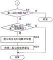
Fig. 7 is a flowchart showing the steps of the second control process.
Fig. 8 is a flowchart showing the steps of the second control process.
Fig. 9 is an explanatory diagram of an effect of the power distribution device.
Fig. 10 is a table showing an information table in embodiment 2.
Fig. 11 is a flowchart showing the steps of the second control process.
Fig. 12 is a flowchart showing the steps of the second control process. .
Detailed Description
[ problem to be solved by the present disclosure ]
When a large number of fuse elements such as fuse links and fuses are manufactured, all fusing thresholds related to the manufactured fuse elements do not coincide, and so-called manufacturing variations occur in the fusing thresholds related to the fuse elements. The magnitude of the manufacturing deviation associated with the fusing threshold is within a certain range.
In the conventional power distribution device described in patent document 1, the minimum value of the fusing threshold exceeds the maximum value of the current flowing through the electric wire in the case of normal operation. In addition, in the conventional power distribution device, even when a current having a current value equal to the maximum value of the fusing threshold value continues to flow, an electric wire that does not generate smoke is used.
The magnitude of manufacturing variations associated with the fusing threshold of the fuse element is large. In this case, since the maximum value of the fusing threshold is large, it is necessary to use an electric wire having a large current value of the allowable current. The electric wire having a large current value of the allowable current is generally thick and heavy. As the electric wire disposed in a vehicle with a limited space, a thicker electric wire is not preferable. In addition, when fuel economy is taken into consideration, a heavy electric wire is not preferable as the electric wire mounted on the vehicle.
An object of the present disclosure is to provide a power distribution device, a power distribution method, and a computer program that can use an electric wire having a small current value of an allowable current.
[ Effect of the present disclosure ]
According to the present disclosure, an electric wire having a small current value of an allowable current can be used.
[ description of embodiments of the invention ]
First, embodiments of the present disclosure will be described. At least some of the embodiments described below may be arbitrarily combined.
(1) One aspect of the present disclosure relates to a power distribution device that distributes power supplied via an electric wire to a plurality of routes, the power distribution device including: a plurality of switches provided on each of the plurality of supply paths; a current detection circuit that detects a current value of a current flowing in the electric wire; a condition determining section that determines whether or not a predetermined condition is satisfied based on the current value detected by the current detecting circuit when the plurality of switches are turned on; and a switching unit configured to switch off a part of the plurality of switches when the condition determining unit determines that the predetermined condition is satisfied.
(2) In the power distribution device according to one aspect of the present disclosure, the power distribution device includes a temperature calculation unit that calculates a wire temperature of the electric wire based on the current value detected by the current detection circuit, and the predetermined condition is that the wire temperature calculated by the temperature calculation unit is equal to or higher than a first temperature threshold.
(3) In the power distribution device according to one aspect of the present disclosure, the power distribution device includes a temperature determination unit that determines whether or not the wire temperature calculated by the temperature calculation unit is equal to or higher than a second temperature threshold that is equal to or lower than the first temperature threshold after the partial switches are switched off by the switching unit, and the switching unit switches off another partial switch among the plurality of switches that is in the on state after the partial switches are switched off when the temperature determination unit determines that the wire temperature is equal to or higher than the second temperature threshold.
(4) In the power distribution apparatus according to one aspect of the present disclosure, when a period during which the wire temperature calculated by the temperature calculation unit is equal to or greater than a second temperature threshold after the switching unit switches the one part of the switches off is equal to or greater than a predetermined period, the switching unit switches off another part of the switches that is still on after the one part of the switches is switched off, the second temperature threshold being equal to or less than the first temperature threshold.
(5) In the power distribution apparatus according to one aspect of the present disclosure, the predetermined condition is that a current value detected by the current detection circuit is equal to or greater than a first current threshold value.
(6) In the power distribution device according to one aspect of the present disclosure, the power distribution device includes a current determination unit that determines whether or not a current value detected by the current detection circuit is equal to or greater than a second current threshold that is equal to or less than the first current threshold after the partial switch is switched off by the switching unit, and the switching unit switches off another partial switch among the plurality of switches that is in an on state after the partial switch is switched off when the current determination unit determines that the current value is equal to or greater than the second current threshold.
(7) In the power distribution apparatus according to one aspect of the present disclosure, when a period during which the current value detected by the current detection circuit is equal to or greater than a second current threshold value after the switching unit switches the one part of the switches off is equal to or greater than a second predetermined period, the switching unit switches off another part of the switches that is still on after the one part of the switches is switched off, the second current threshold value being equal to or less than the first current threshold value.
(8) One embodiment of the present disclosure relates to a power distribution method including the steps of: determining whether or not a predetermined condition is satisfied based on a current value of a current flowing in an electric wire in a case where a plurality of switches arranged on each of a plurality of supply paths for distribution of electric power supplied via the electric wire are turned on; and switching a part of the switches among the plurality of switches to off when it is determined that the predetermined condition is satisfied.
(9) One embodiment of the present disclosure relates to a computer program for causing a computer to execute the steps of: determining whether or not a predetermined condition is satisfied based on a current value of a current flowing in an electric wire in a case where a plurality of switches arranged on each of a plurality of supply paths for distribution of electric power supplied via the electric wire are turned on; and switching a part of the switches among the plurality of switches to off when it is determined that the predetermined condition is satisfied.
In the power distribution device, the power distribution method, and the computer program according to the above-described one aspect, for example, it is assumed that the fuse element that fuses when a current having a current value equal to or larger than a fuse threshold value continues to flow is connected in series to the electric wire. The current flows in the fuse element and the electric wire, and is shunted to the plurality of paths. In the case where the plurality of switches provided on each of the plurality of supply paths are turned on, when a value of a current value based on a current flowing in the electric wire or the current value satisfies a predetermined condition, a part of the switches are switched off. As a result, the maximum value of the current flowing through the electric wire is reduced in the case of normal operation.
When the current value is equal to or greater than the fusing threshold value, the fusing element is not instantaneously fused. Therefore, the current value may exceed the fusing threshold value even in the case of normal operation. Even in this case, since the part of the switches is turned off before the fuse element is blown, the possibility that the fuse element is blown by mistake is low.
As described above, when a large amount of fuse elements are manufactured, the minimum value of the fusing threshold value of the manufactured fuse elements may be smaller than the maximum value of the current flowing through the electric wire in the case of normal operation. In this case, since the maximum value of the fusing threshold is small, an electric wire having a small current value of the allowable current can be used.
In the power distribution device according to the above-described aspect, when the plurality of switches are on, the part of the switches are switched off when the electric wire temperature becomes equal to or higher than the first temperature threshold value.
In the power distribution apparatus according to the above-described aspect, when the electric wire temperature is equal to or higher than the second temperature threshold after the one part of the switches is turned off, another part of the switches among the plurality of switches in the on state is turned off. Thus, the fuse element is less likely to be erroneously blown despite the normal operation.
In the power distribution device according to the above-described one aspect, even if the one part of the switches is turned off, when the period in which the electric wire temperature is equal to or higher than the second temperature threshold value reaches a predetermined period or longer, another part of the switches in the on state is turned off. This reduces the possibility of erroneous blowing of the fuse element despite normal operation.
In the power distribution device according to the above-described aspect, when the plurality of switches are turned on, a part of the switches are turned off when the current value becomes equal to or greater than a first current threshold value.
In the power distribution device according to the above-described one aspect, when the current value of the current flowing through the electric wire after the one part of the switches is switched off is equal to or greater than the second current threshold value, the other part of the switches in the on state is switched off. This reduces the possibility of erroneous blowing of the fuse element despite normal operation.
In the power distribution device according to the above-described one aspect, even if the one part of the switches is turned off, when a period in which a current value of a current flowing through the electric wire is equal to or more than the second current threshold value reaches a predetermined period or more, another part of the switches in the on state is turned off. This reduces the possibility of erroneous blowing of the fuse element despite normal operation.
[ details of the embodiments of the present disclosure ]
Specific examples of the power distribution device according to the embodiments of the present disclosure will be described below with reference to the drawings. The present invention is not limited to these examples, but is defined by the claims, and is intended to include all modifications within the meaning and range equivalent to the claims.
(embodiment mode 1)
Fig. 1 is a block diagram showing a main part configuration of a power supply system 1 in embodiment 1. The power supply system 1 is suitably mounted on a vehicle, and includes a battery 10, a power supply box 11, a power distribution device 12, six loads L1, L2, and L3, and an electric wire W. A fuse element 20 such as a fuse link or a fuse is accommodated in the power supply box 11.
The positive electrode of battery 10 is connected to one end of fuse element 20 of power supply box 11. The negative electrode of the battery 10 is grounded. The other end of fuse element 20 is connected to one end of wire W. The other end of the wire W is connected to the power distribution device 12. The power distribution device 12 is also individually connected to one ends of the six loads L1, L2, L3. The other ends of the loads L1, L2, and L3 are grounded.
The battery 10 supplies electric power to the power distribution device 12 via the fuse element 20 and the electric wire W. At this time, current flows from the positive electrode of battery 10 to fuse element 20 and wire W in this order. When a current having a current value equal to or greater than the fusing threshold value continues to flow through the fusing element 20, the fusing element 20 is fused. This stops the energization of the wire W, thereby protecting the wire W from the overcurrent.
The power distribution device 12 receives an enable signal indicating that power supply to the six loads L1, L2, and L3 is enabled, and a stop signal indicating that power supply to the six loads L1, L2, and L3 is stopped. The permission signal is, for example, a signal indicating turning on of an ignition switch of the vehicle. The stop signal is, for example, a signal indicating turning off of an ignition switch.
When the permission signal is input, the power distribution device 12 distributes the power supplied from the battery 10 via the electric wire W to the six loads L1, L2, and L3. Each of the loads L1, L2, and L3 is an electrical device mounted on the vehicle, and operates using electric power supplied from the power distribution device 12. When the stop signal is input, the power distribution device 12 stops the distribution of the power to the six loads L1, L2, and L3.
The power distribution device 12 repeatedly calculates the wire temperature of the electric wire W based on the current value of the current flowing in the electric wire W (hereinafter referred to as wire current value). The power distribution device 12 changes the load, which distributes power, among the six loads L1, L2, L3 according to the calculated wire temperature.
Fig. 2 is a block diagram showing the main part structure of the power distribution device 12. The power distribution device 12 includes a resistor 30, a current detection circuit 31, a temperature detection circuit 32, a microcomputer (hereinafter referred to as a microcomputer) 33, three switches A1, A2, and A3, three drive circuits D1, D2, and D3, and six fuse elements F1, F2, and F3. The switches A1, A2, A3 are each an N-channel type FET (Field Effect Transistor).
As described above, one end of the electric wire W is connected to the other end of the fusing element 20 of the power supply box 11. The other end of the wire W is connected to one end of the resistor 30. The other end of the resistor 30 is connected to the drain of each of the switches A1, A2, and A3. The source of switch A1 is connected to one end of two fuse elements F1. The other ends of the two fuse elements F1 are connected to one ends of two loads L1, respectively.
Similarly, the source of switch A2 is connected to one end of two fuse elements F2. The other ends of the two fuse elements F2 are connected to one ends of two loads L2, respectively. The source of switch A3 is connected to one end of two fuse elements F3. The other ends of the two fuse elements F3 are connected to one ends of two loads L3, respectively.
One end and the other end of the resistor 30 are individually connected to the current detection circuit 31. The gates of the switches A1, A2, and A3 are connected to the driving circuits D1, D2, and D3, respectively. The current detection circuit 31, the temperature detection circuit 32, and the drive circuits D1, D2, and D3 are individually connected to the microcomputer 33.
When the voltage value of the gate with reference to the potential of the source is equal to or greater than a certain voltage value, a current can flow through the drain and the source to each of the switches A1, A2, and A3. At this time, the switches A1, A2, and A3 are turned on. When the voltage value of the gate with reference to the potential of the source is smaller than a predetermined voltage value, the switches A1, A2, and A3 do not allow a current to flow through the drain and the source. At this time, the switches A1, A2, and A3 are turned off.
The microcomputer 33 outputs a high-level voltage or a low-level voltage to each of the driving circuits D1, D2, and D3. When the voltage inputted from the microcomputer 33 is switched from the low-level voltage to the high-level voltage, the driving circuit D1 increases the voltage value of the gate of the switch A1 with reference to the ground potential. Thus, in the switch A1, the voltage value of the gate with the potential of the source as a reference becomes equal to or higher than a certain value, and the switch A1 is switched on.
When the voltage inputted from the microcomputer 33 is switched from the high-level voltage to the low-level voltage, the drive circuit D1 lowers the voltage value of the gate of the switch A1 with reference to the ground potential. Thus, in the switch A1, the voltage value of the gate with the potential of the source as a reference is less than a certain value, and the switch A1 is switched off.
Similarly to the driving circuit D1, the driving circuits D2 and D3 switch the switches A2 and A3 on or off in accordance with the voltage input from the microcomputer 33. In the description of the switching by the driving circuit D1, the switch A1 and the driving circuit D1 are replaced with the switch A2 and the driving circuit D2, respectively, whereby the switching by the driving circuit D2 can be described. In the description of the switching by the driving circuit D1, the switch A1 and the driving circuit D1 are replaced with the switch A3 and the driving circuit D3, respectively, so that the switching by the driving circuit D3 can be described.
When switch A1 is turned on, a current flows from the positive electrode of battery 10 to fuse element 20, wire W, resistor 30, switch A1, fuse element F1, and load L1 in this order, and power is supplied to load L1. In this way, the switch A1 is provided on the supply path for supplying power from the other end of the wire W to the load L1. When the switch A1 is turned on, power is supplied to the two loads L1. When the switch A1 is off, power is not supplied to the two loads L1, and the two loads L1 stop operating.
Similarly, when switch A2 is turned on, a current flows from the positive electrode of battery 10 to fuse element 20, wire W, resistor 30, switch A2, fuse element F2, and load L2 in this order, and power is supplied to load L2. In this way, the switch A2 is provided on the supply path for supplying electric power from the other end of the wire W to the load L2. When the switch A2 is turned on, power is supplied to the two loads L2. When the switch A2 is off, power is not supplied to the two loads L2, and the two loads L2 stop operating.
When switch A3 is turned on, a current flows from the positive electrode of battery 10 to fuse element 20, wire W, resistor 30, switch A3, fuse element F3, and load L3 in this order, and power is supplied to load L3. In this way, the switch A3 is provided on the supply path for supplying electric power from the other end of the wire W to the load L3. When the switch A3 is turned on, power is supplied to the two loads L3. When the switch A3 is off, power is not supplied to the two loads L3, and the two loads L3 stop operating.
In the power distribution device 12, the power supplied from the battery 10 via the electric wire W is distributed to six loads L1, L2, and L3 via three supply paths. The number N of supply paths is 3.
When a current having a current value equal to or greater than a predetermined threshold value continues to flow through each of the fuse elements F1, F2, and F3, the fuse element is blown. This protects the wires connected to one end of each of the loads L1, L2, and L3 from the overcurrent. Fuse elements F1, F2, and F3 are each a fuse link, a fuse wire, or the like.
The current detection circuit 31 detects a wire current value, which is a current value of the current flowing through the resistor 30 d. The current detection circuit 31 outputs analog current information indicating the detected current value of the electric wire to the microcomputer 33. The current information is, for example, a voltage value proportional to the electric wire current value.
The temperature detection circuit 32 detects an ambient temperature of an environment in which the power distribution device 12 is disposed in the vehicle. The ambient temperature is, for example, the ambient temperature of the electric wire W. The temperature detection circuit 32 is configured by using, for example, a thermistor whose resistance value changes according to the ambient temperature. The temperature detection circuit 32 outputs analog temperature information indicating the detected ambient temperature to the microcomputer 33. The temperature information is, for example, a voltage value that changes according to the ambient temperature.
The microcomputer 33 receives an enable signal and a stop signal. The microcomputer 33 switches the voltage to be output to each of the drive circuits D1, D2, and D3 to a high-level voltage or a low-level voltage in accordance with the input signal, the electric wire current value indicated by the current information input from the current detection circuit 31, and the ambient temperature indicated by the temperature information input from the temperature detection circuit 32. As described above, the driving circuits D1, D2, D3 each switch the switches A1, A2, A3 on or off in accordance with the voltage output from the microcomputer 33.
Fig. 3 is a block diagram showing the main part structure of the microcomputer 33. The microcomputer 33 includes input units 40, 41, and 42, a/ D conversion units 43 and 44, a timer 45, a storage unit 46, a control unit 47, and output units B1, B2, and B3. The input unit 40, a/ D conversion units 43 and 44, a timer 45, a storage unit 46, a control unit 47, and output units B1, B2, and B3 are connected to an internal bus 48.
The a/ D converters 43 and 44 are connected to the input units 41 and 42, respectively. The input unit 41 is also connected to the current detection circuit 31. The input portion 42 is also connected to the temperature detection circuit 32.
The input unit 40 receives an enable signal and a stop signal. When the permission signal or the stop signal is input, the input unit 40 notifies the control unit 47 of the input signal.
Analog current information is input from the current detection circuit 31 to the input unit 41. When the analog current information is input, the input unit 41 outputs the input analog current information to the a/D conversion unit 43. The a/D conversion section 43 converts the analog current information input from the input section 41 into digital current information. The control section 47 acquires the digital current information converted by the a/D conversion section 43 from the a/D conversion section 43.
The analog temperature information is input from the temperature detection circuit 32 to the input unit 42. When the analog temperature information is input, the input unit 42 outputs the input analog temperature information to the a/D conversion unit 44. The a/D conversion section 44 converts the analog current information input from the input section 42 into digital current information. The control section 47 acquires the digital temperature information converted by the a/D conversion section 44 from the a/D conversion section 44.
The output units B1, B2, and B3 output high-level voltages or low-level voltages to the driving circuits D1, D2, and D3, respectively. The output units B1, B2, and B3 each switch the voltage to be output to the drive circuits D1, D2, and D3 to a high-level voltage or a low-level voltage in accordance with an instruction from the control unit 47. The driving circuits D1, D2, and D3 switch the switches A1, A2, and A3 on or off according to the voltages input from the output units B1, B2, and B3.
When the output unit B1 outputs a high-level voltage, the switch A1 is turned on. When the output unit B1 outputs a low-level voltage, the switch A1 is turned off. Similarly, when the output unit B2 outputs a high-level voltage, the switch A2 is turned on. When the output unit B2 outputs a low-level voltage, the switch A2 is turned off. When the output unit B3 outputs a high-level voltage, the switch A3 is turned on. When the output unit B3 outputs a low-level voltage, the switch A3 is turned off.
The timer 45 starts and ends the counting of time in response to an instruction from the control unit 47. The control unit 47 reads the time counted by the timer 45 from the timer 45.
The storage unit 46 is a nonvolatile memory. The storage unit 46 stores a computer program 50 and an information table 51. The control Unit 47 has a Processing element for executing Processing, and includes, for example, a CPU (Central Processing Unit). The processing elements of the control section 47 execute a first control process and a second control process for controlling the power supply to the six loads L1, L2, L3 and a temperature calculation process for calculating the wire temperature of the electric wire W by executing the computer program 50. The control unit 47 executes the first control process, the second control process, and the temperature calculation process in parallel in a time-sharing manner. The computer program 50 is for causing a processing element (computer) of the control section 47 to execute the first control process, the second control process, and the temperature calculation process.
The computer program 50 may be stored in the storage medium E so as to be readable by the processing element of the control unit 47. In this case, the computer program 50 read from the storage medium E by a reading device not shown is stored in the storage unit 46. The storage medium E is an optical disk, a flexible disk, a magnetic disk, a magneto-optical disk, a semiconductor memory, or the like. The optical disk is a Compact Disc (CD) -ROM (Read Only Memory), a Digital Versatile Disc (DVD) -ROM, a Blu-ray (registered trademark) Disc, or the like. The magnetic disk is, for example, a hard disk. Further, the computer program 50 may be downloaded from an external device, not shown, connected to a communication network, not shown, and the downloaded computer program 50 may be stored in the storage unit 46.
The number of processing elements included in the control unit 47 is not limited to 1, and may be 2 or more. When the control unit 47 has a plurality of processing elements, the plurality of processing elements may cooperatively execute the first control process, the second control process, and the temperature calculation process.
The control section 47 periodically executes the temperature calculation process. In the temperature calculation process, the control section 47 calculates a temperature difference between the ambient temperature of the environment in which the power distribution device 12 is disposed and the wire temperature of the wires W, and adds the ambient temperature to the calculated temperature difference, thereby calculating the wire temperature. The temperature difference is calculated based on the ambient temperature, the preceding temperature difference calculated in the last temperature calculation process, and the electric wire current value.
Fig. 4 is a diagram showing the information table 51. The information table 51 shows various kinds of information used in the first control process, the second control process, and the temperature calculation process. As shown in fig. 4, the information table 51 includes an ambient temperature field, a previous temperature difference field, a wire temperature field, a first temperature threshold field, a second temperature threshold field, a time threshold field, a first flag field, and a second flag field.
The ambient temperature field, the previous temperature difference field, and the electric wire temperature field each store an ambient temperature, a previous temperature difference, and an electric wire temperature. These values are updated by the control unit 47. The first temperature threshold field and the second temperature threshold field each store a first temperature threshold and a second temperature threshold for comparison with the wire temperature. In the time threshold field, a time threshold value for comparison with the counted time counted by the timer 45 is stored. The first temperature threshold, the second temperature threshold, and the time threshold are constant values and are pre-stored. The second temperature threshold is below the first temperature threshold.
The first flag field stores a value of the first flag. The first flag has a value of 0 or 1. The value of the first flag is also updated by the control unit 47. The "value of the first flag is 0" means that the switch A1 is turned on. The "value of the first flag is 1" means that the switch A1 is off.
Likewise, the value of the second flag is stored in the second flag field. The value of the second flag is 0 or 1. The value of the second flag is also updated by the control unit 47. The "value of the second flag is 0" means that the switch A2 is turned on. The "value of the second flag is 1" means that the switch A2 is off.
Fig. 5 is a flowchart showing the steps of the first control process. The control section 47 periodically executes the first control process. In the first control process, the control unit 47 first determines whether or not the input unit 40 has input the permission signal (step S1). When determining that the permission signal is input (yes in S1), the control unit 47 updates the previous temperature difference in the information table 51 to 0 (step S2), and updates the values of the first flag and the second flag to 0 (step S3). At the time when the permission signal is input to the input unit 40, the control unit 47 updates the previous temperature difference to 0 in step S2, assuming that the wire temperature substantially matches the ambient temperature.
Next, the control unit 47 instructs the output units B1, B2, and B3 to turn on the switches A1, A2, and A3 (step S4). Thereby, the output units B1, B2, and B3 switch the voltages output to the driving circuits D1, D2, and D3 to high-level voltages, respectively. The drive circuits D1, D2, D3 each switch on the switches A1, A2, A3.
When the switches A1, A2, and A3 are turned on, the electric power supplied from the positive electrode of the battery 10 via the wire W is distributed to the six loads L1, L2, and L3 via three supply paths in which the switches A1, A2, and A3 are provided.
When determining that the permission signal is not input (no in S1), the control unit 47 determines whether or not the stop signal is input to the input unit 40 (step S5). When determining that the stop signal is input (yes in S5), the control unit 47 instructs the output units B1, B2, and B3 to turn off the switches A1, A2, and A3 (step S6).
Thereby, the output units B1, B2, and B3 switch the voltages output to the drive circuits D1, D2, and D3 to low-level voltages, respectively. The drive circuits D1, D2, D3 each switch the switches A1, A2, A3 off. When the switches A1, A2, and A3 are switched off, the supply of electric power to the six loads L1, L2, and L3 is stopped.
After one of steps S4 and S6 is executed, or when it is determined that the stop signal is not input (no in S5), the control unit 47 ends the first control process.
As described above, in the power distribution device 12, when the permission signal is input to the input unit 40, the drive circuits D1, D2, and D3 switch the switches A1, A2, and A3 on, and the power supplied via the power line W is distributed to the six loads L1, L2, and L3. When the stop signal is input to the input unit 40, the drive circuits D1, D2, and D3 switch off the switches A1, A2, and A3, and stop the supply of power to the six loads L1, L2, and L3.
Fig. 6 is a flowchart showing the steps of the temperature calculation process. The control unit 47 periodically executes the temperature calculation process during a period from when the permission signal is input from the input unit 40 to when the stop signal is input from the input unit 40. In the temperature calculation process, the control unit 47 first acquires temperature information from the a/D conversion unit 44 (step S11). Next, the control unit 47 updates the ambient temperature in the information table 51 to the ambient temperature indicated by the temperature information acquired in step S11 (step S12). The control section 47 acquires the current information from the a/D conversion section 43 after executing step S12 (step S13). The electric wire current value indicated by the current information acquired from the a/D conversion portion 43 is the electric wire current value detected by the current detection circuit 31.
As described above, in the temperature calculation process, the control section 47 calculates the temperature difference between the wire temperature and the ambient temperature. The control unit 47 updates the previous temperature difference in the information table 51 to the calculated temperature difference. Therefore, the preceding temperature difference of the information table 51 is the temperature difference calculated in the last temperature calculation process. In the temperature calculation process performed for the first time after the permission signal is input to the input unit 40, it is considered that the preceding temperature difference is 0.
After executing step S13, the control section 47 calculates a temperature difference between the wire temperature and the ambient temperature based on the ambient temperature and the previous temperature difference of the information table 51 and the wire current value indicated by the current information acquired in step S13 (step S14). In step S14, the control unit 47 calculates a temperature difference that decreases due to heat radiation performed during one cycle in accordance with the execution of the temperature calculation process, based on the preceding temperature difference. Further, the control unit 47 calculates the range of increase in the wire temperature that increases due to heat generation performed during one cycle involved in the execution of the temperature calculation process, based on the ambient temperature, the preceding temperature difference, and the wire current value.
The control section 47 calculates the temperature difference between the wire temperature and the ambient temperature by adding the magnitude of the increase in the wire temperature that increases due to heat generation to the temperature difference that decreases due to heat dissipation.
Next, the control unit 47 updates the previous temperature difference in the information table 51 to the temperature difference calculated in step S14 (step S15). The updated previous temperature difference is used in the calculation of the temperature difference in the next temperature calculation process. After step S15 is executed, the control unit 47 calculates the wire temperature of the wire W by adding the ambient temperature of the information table 51 to the temperature difference calculated in step S14 (step S16). The control unit 47 functions as a temperature calculation unit. Next, the control unit 47 updates the wire temperature in the information table 51 to the wire temperature calculated in step S16 (step S17), and ends the temperature calculation process.
As described above, the control section 47 periodically executes the temperature calculation process, and updates the wire temperature of the information table 51. The wire temperature of the information table 51 indicates the latest wire temperature.
Fig. 7 and 8 are flowcharts showing steps of the second control process. The control unit 47 periodically executes the second control process during a period from when the permission signal is input from the input unit 40 to when the stop signal is input from the input unit 40. The cycle involved in the execution of the temperature calculation process is sufficiently shorter than the cycle involved in the execution of the second control process. Thereby, the wire temperature of the information table 51 is updated also during the execution of the second control process.
In the second control process, the control unit 47 first determines whether or not the value of the first flag in the information table 51 is 0 (step S21). When determining that the value of the first flag is 0 (yes in S21), the control unit 47 determines whether or not the wire temperature in the information table 51 is equal to or higher than the first temperature threshold value in the information table 51 (step S22).
As described above, the control unit 47 periodically executes the second control process during a period from when the permission signal is input from the input unit 40 to when the stop signal is input from the input unit 40. In the second control process, when the permission signal is input to the input unit 40, the driving circuits D1, D2, and D3 turn on the switches A1, A2, and A3, and the control unit 47 updates the values of the first flag and the second flag to 0. In addition, in a state where the value of the first flag is 0, the value of the second flag is not updated to 1. Thus, in step S21, the "value of the first flag is 0" means that the switches A1, A2, and A3 are turned on. Therefore, step S22 is executed with the switches A1, A2, and A3 turned on.
The wire temperature of the information table 51 is a value calculated based on the wire current value indicated by the current information, that is, the wire current value detected by the current detection circuit 31 in the temperature calculation process. The control unit 47 also functions as a condition determination unit. "the wire temperature is equal to or higher than the first temperature threshold" is a predetermined condition.
When the control unit 47 determines that the wire temperature is equal to or higher than the first temperature threshold value (yes in S22), it instructs the output unit B1 to switch the switch A1 to off (step S23). Thereby, the output unit B1 switches the voltage output to the drive circuit D1 to the low level voltage, and the drive circuit D1 switches the switch A1 to off. The entire drive circuits D1, D2, and D3 function as switching units. The number K of switches A1 is 1. As described above, since N is 3, k is a natural number smaller than N. In addition, N and K satisfy that N is more than or equal to K +2.
When the switch A1 is switched off, the supply of power to the two loads L1 via the switch A1 is stopped. This reduces the wire current value and also reduces the wire temperature. Further, in the power supply system 1, the maximum value of the electric wire current value in the case of performing a normal operation is also reduced.
After executing step S23, the control unit 47 updates the value of the first flag to 1 in the information table 51 (step S24). Next, the control unit 47 instructs the timer 45 to start the time counting (step S25), and determines whether or not the wire temperature of the information table 51 is lower than the second temperature threshold of the information table 51 (step S26).
When the control unit 47 determines that the wire temperature is equal to or higher than the second temperature threshold (no in S26), it determines whether or not the time counted by the timer 45 is equal to or higher than the time threshold of the information table 51 (step S27). "determining whether or not the counted time is equal to or greater than the time threshold in step S27" corresponds to determining whether or not the time threshold is or greater during which the wire temperature of the information table 51 is equal to or greater than the second temperature threshold after the drive circuit D1 switches the switch A1 off. The term "the counted time is equal to or more than the time threshold" means that the time threshold is equal to or more than the time threshold while the wire temperature in the information table 51 is equal to or more than the second temperature threshold after the drive circuit D1 switches the switch A1 off. The control unit 47 also functions as a period determination unit.
When determining that the counted time is less than the time threshold (no in S27), the control unit 47 executes step S26 and waits until the wire temperature is less than the second temperature threshold or the counted time is equal to or greater than the time threshold. When determining that the counted time is equal to or greater than the time threshold (yes in S27), the control unit 47 instructs the output unit B2 to switch the switch A2 to off (step S28). Thereby, the output unit B2 switches the voltage output to the drive circuit D2 to the low level voltage, and the drive circuit D2 switches the switch A2 to off. At the time when step S27 is executed, the switch A1 is turned off, and the switches A2 and A3 are turned on. The number of switches A2 corresponds to M and is 1. As previously described, N is 3 and K is 1.M is a natural number less than (N-K).
When the switch A2 is switched off, the supply of power to the two loads L2 via the switch A2 is stopped. This reduces the wire current value and also reduces the wire temperature. Further, in the power supply system 1, the maximum value of the electric wire current value in the case of performing a normal operation is also reduced.
After executing step S28, the control unit 47 updates the value of the second flag to 1 in the information table 51 (step S29). When determining that the wire temperature is lower than the second temperature threshold value (yes in S26), or after executing step S29, the control unit 47 instructs the timer 45 to end the time measurement (step S30). Thereby, the timer 45 ends the counting. When determining that the wire temperature is equal to or lower than the first temperature threshold value (no in S22), or after executing step S30, the control unit 47 ends the second control process.
When the period during which the wire temperature is equal to or higher than the second temperature threshold value after the drive circuit D1 switches the switch A1 off is equal to or higher than the time threshold value, the drive circuit D2 switches the switch A2 off, and the control unit 47 updates the value of the second flag to 1. In this case, the control unit 47 ends the second control process in a state where the values of the first flag and the second flag are 1. When the wire temperature is lower than the second temperature threshold value before the period in which the wire temperature is equal to or higher than the second temperature threshold value after the drive circuit D1 switches the switch A1 off is equal to or higher than the time threshold value, the control unit 47 ends the second control process in a state where the values of the first flag and the second flag are 1 and 0, respectively.
When determining that the value of the first flag is not 0, that is, that the value of the first flag is 1 (no in S21), the control unit 47 determines whether or not the value of the second flag is 0 in the information table 51 (step S31). The phrase "the values of the first flag and the second flag are 1 and 0 respectively" means that the wire temperature calculated by the control unit 47 in the temperature calculation process after the drive circuit D1 switches the switch A1 off is less than the second temperature threshold.
If the control unit 47 determines that the value of the second flag is not 0, that is, the value of the second flag is 1 (S31: no), it ends the second control process. As described above, the "value of the second flag is 1" indicates that the switch A2 is off.
If the control unit 47 determines that the value of the second flag is 0 (yes in S31), it determines whether or not the wire temperature in the information table 51 is equal to or higher than the second temperature threshold value in the information table 51 (step S32). The control unit 47 also functions as a temperature determination unit. When the control unit 47 determines that the wire temperature is equal to or higher than the second temperature threshold value (yes in S32), it instructs the output unit B2 to switch the switch A2 to off (step S33). Thereby, the output unit B2 switches the voltage output to the drive circuit D2 to the low level voltage, and the drive circuit D2 switches the switch A2 to off. At the timing of executing step S33, the switch A1 is turned off, and the switches A2 and A3 are turned on.
As described above, when the switch A2 is switched off, the supply of power to the two loads L2 via the switch A2 is stopped. This reduces the wire current value and also reduces the wire temperature. Further, in the power supply system 1, the maximum value of the electric wire current value in the case of performing a normal operation is also reduced.
After executing step S33, the control unit 47 updates the value of the second flag to 1 in the information table 51 (step S34). If the control unit 47 determines that the wire temperature is lower than the second temperature threshold value (no in S32), or after executing step S34, it ends the second control process.
As described above, in the power distribution device 12, when the electric wire temperature reaches the first temperature threshold or more, the drive circuit D1 switches the switch A1 off. When the period during which the wire temperature is equal to or higher than the second temperature threshold after the drive circuit D1 switches the switch A1 off is equal to or higher than the time threshold, the drive circuit D2 switches the switch A2 off. In addition, the drive circuit D2 also switches the switch A2 off when the wire temperature is equal to or higher than the second temperature threshold after being lower than the second temperature threshold. Thus, in the power supply system 1, the maximum value of the electric wire current value in the case of performing a normal operation is reduced. The switch A3 remains on until the stop signal is input to the input unit 40.
Therefore, after the power supply to the load L1 is stopped, the power supply to the load L2 is stopped. As long as the stop signal is not input, the power supply to the load L3 is continued. The importance of the load L3 is higher than the importance of the loads L1 and L2, and the importance of the load L2 is higher than the importance of the load L1. The load L3 is, for example, an electrical device that affects the driving of the vehicle. The loads L1 and L2 are, for example, electrical devices that do not directly affect the driving of the vehicle. The electrical devices affecting the driving of the vehicle are headlights or brake lights, etc. The electric devices that do not affect the driving of the vehicle are wipers, air conditioners, navigation systems, and the like.
Fig. 9 is an explanatory diagram of an effect of the power distribution device 12. Fig. 9 shows smoke emission characteristics of the electric wire W and fusing characteristics of the fusing element 20. The vertical axis shows the wire current value. The horizontal axis shows the energization period during which the current flows in the electric wire W. The wire current value is also a current value of a current flowing in the fuse element 20. The energization period during which the current flows through the electric wire W corresponds to a period during which the current flows through the fuse element 20.
The fuming characteristics of the wire W show the current value of the wire at which fuming occurred and the energization period. The larger the current value of the wire is, the more smoke generation occurs in a short energization period. The fusing characteristics of the fusing element 20 show the current value of the wire at which fusing occurs and the energization period. The larger the current value of the electric wire is, the more the fuse element 20 is fused in a shorter period of energization. With respect to the fusing element 20, the minimum value of the current value of the electric wire at which the fusing occurs is the fusing threshold value.
When the fuse element 20 is manufactured in a large quantity, all the fusing threshold values of the manufactured fuse elements 20 do not match, and so-called manufacturing variations occur in the fusing threshold values of the fuse elements 20. Fig. 9 shows a fusing characteristic in which the fusing threshold is the largest and a fusing characteristic in which the fusing threshold is the smallest. The magnitude of the manufacturing deviation associated with the fusing threshold is within a certain range. In the power supply system 1, one of the fuse elements 20 manufactured in large numbers is used. With respect to the common electric wire current value, the fusing element 20 is fused before smoking occurs at the electric wire W.
The maximum value of the wire current value in the case of normal operation is shown by a broken line. As shown by the fusing characteristics of the fusing element 20, even when the current value of the electric wire is equal to or greater than the fusing threshold value, the fusing element 20 is not instantaneously fused.
Hereinafter, the maximum value of the wire current value in the case of performing the normal operation is simply referred to as "the maximum value of the wire current value". In the power distribution device 12, when the switches A1, A2, and A3 are on, the switch A1 is switched off when the wire temperature calculated based on the wire current value becomes equal to or higher than the first temperature threshold value. Thereby, the maximum value of the electric wire current value is reduced. Therefore, the maximum value of the electric wire current value may also exceed the fusing threshold value of the fusing element 20. Even in this case, since the switch A1 is turned off before the fusing element 20 is fused, the fusing element 20 is less likely to be fused by mistake.
As described above, when the fuse element 20 is manufactured in a large quantity, the minimum value of the fusing threshold value of the manufactured fuse element 20 may exceed the maximum value of the current value of the electric wire. In this case, since the maximum value of the fusing threshold is small, the electric wire having a small minimum value of the electric wire current value at which smoke emission occurs, which is the current value of the allowable current, can be used as the electric wire W.
After the switch A1 is switched off and the wire temperature is lower than the second temperature threshold, the switch A2 is switched off when the wire temperature is equal to or higher than the second temperature threshold. Further, even if the switch A1 is switched off, the switch A2 is switched off when the time period during which the electric wire temperature is equal to or higher than the second temperature threshold value is equal to or higher than the time threshold value. When the drive circuit D2 switches the switch A2 off in a state where the switch A1 is off, the maximum value of the wire current value further decreases. Thus, the fuse element 20 is less likely to be erroneously blown despite the normal operation.
When the switches A1 and A2 are turned off, the maximum value of the electric wire current value is smaller than the minimum value of the fusing threshold value. Accordingly, when the switches A1 and A2 are off, the fusing element 20 is not fused unless a failure occurs. In addition, the average value of the electric wire current values in the case of normal operation is smaller than the minimum value of the fusion threshold value. This reduces the possibility that the switches A1 and A2 are switched off.
It is assumed that at least one of the switches A1, A2 is open. Even in this case, when the stop signal and the permission signal are sequentially input to the input unit 40, the control unit 47 causes the drive circuits D1, D2, and D3 to turn on the switches A1, A2, and A3 in the first control process.
The previous temperature difference may be a previously calculated temperature difference. Thus, the preceding temperature difference is not limited to the temperature difference calculated in the previous temperature calculation process, and may be, for example, the temperature difference calculated in the previous temperature calculation process.
(embodiment mode 2)
In embodiment 1, the control unit 47 determines whether to switch the switch A1 off based on the wire temperature. However, the value used for the determination of whether to switch the switch A1 off is not limited to the wire temperature.
Hereinafter, embodiment 2 is different from embodiment 1 in point. The configuration other than the configuration described later is common to embodiment 1. Accordingly, the same reference numerals as those in embodiment 1 are assigned to the components common to embodiment 1, and the description thereof is omitted.
Fig. 10 is a table showing the information table 51 in embodiment 2. As in embodiment 1, the information table 51 is provided with a time threshold field, a first flag field, and a second flag field. The time threshold value, the value of the first flag, and the value of the second flag are stored in each of the time threshold field, the first flag field, and the second flag field. The time threshold is a constant value and is stored in advance. The respective values of the first flag and the second flag are updated by the control unit 47. The meaning of the value of each of the first and second flags is the same as that in embodiment 1.
The information table 51 in embodiment 2 is further provided with a first current threshold field and a second current threshold field. The first current threshold field and the second current threshold field each store a first current threshold and a second current threshold for comparison with the electric wire current value. The first current threshold and the second current threshold are constant values and are stored in advance. The second current threshold is less than or equal to the first current threshold.
In embodiment 2, since it is not necessary to calculate the wire temperature, the control unit 47 does not execute the temperature calculation process. In the power distribution device 12 according to embodiment 2, the temperature detection circuit 32 and the input unit 42 and the a/D conversion unit 44 included in the microcomputer 33 are not required.
Fig. 11 and 12 are flowcharts showing steps of the second control process. Similarly to embodiment 1, the control unit 47 periodically executes the second control process during a period from when the permission signal is input from the input unit 40 to when the stop signal is input from the input unit 40. Steps S41, S44 to S46, S50 to S53, S56, and S57 of the second control processing in embodiment 2 are the same as steps S21, S23 to S25, S28 to S31, S33, and S34 of the second control processing in embodiment 1, respectively. Thus, detailed descriptions of steps S41, S44 to S46, S50 to S53, S56, and S57 will be omitted.
When determining that the value of the first flag is 0 (yes in S41), the control unit 47 acquires current information from the a/D conversion unit 43 (step S42), and determines whether or not the wire current value indicated by the acquired current information is equal to or greater than the first current threshold value of the information table 51 (step S43). As described above, the control unit 47 periodically executes the second control process during a period from when the permission signal is input from the input unit 40 to when the stop signal is input from the input unit 40. In the first control process, when the input unit 40 receives the permission signal, the driving circuits D1, D2, and D3 turn on the switches A1, A2, and A3, and the control unit 47 updates the values of the first flag and the second flag to 0. Further, in a state where the value of the first flag is 0, the value of the second flag is not updated to 1.
Thus, in step S41, the "value of the first flag being 0" means that the switches A1, A2, A3 are turned on. Therefore, steps S42 and S43 are performed with the switches A1, A2, and A3 turned on. The electric wire current value indicated by the current information is the electric wire current value detected by the current detection circuit 31. In embodiment 2, "the electric wire current value is equal to or greater than the first current threshold value" is a predetermined condition.
When the control unit 47 determines that the wire current value is equal to or greater than the first current threshold value (yes in S43), it sequentially executes steps S44 to S46. The control section 47 acquires the current information from the a/D conversion section 43 after executing step S46 (step S47), and determines whether or not the electric wire current value indicated by the acquired current information is smaller than the second current threshold value of the information table 51 (step S48).
When the control unit 47 determines that the wire current value is equal to or greater than the second current threshold value (no in S48), it determines whether or not the counted time counted by the timer 45 is equal to or greater than the time threshold value of the information table 51 (step S49). The "determination of whether or not the counted time is equal to or greater than the time threshold" in step S49 corresponds to a determination of whether or not the period during which the electric wire current value is equal to or greater than the second temperature threshold after the drive circuit D1 switches the switch A1 off is equal to or greater than the time threshold. The term "the counted time is equal to or more than the time threshold" means that the time threshold is equal to or more than the time threshold while the electric wire current value in the information table 51 is equal to or more than the second current threshold after the drive circuit D1 switches the switch A1 off. The control unit 47 also functions as a second period determination unit.
When determining that the counted time is less than the time threshold (no in S49), the control unit 47 executes step S47 and waits until the electric wire current value is less than the second current threshold or the counted time is equal to or greater than the time threshold. When the control unit 47 determines that the counted time is equal to or longer than the time threshold (yes in S49), it sequentially executes steps S50 and S51. At the timing of executing step S50, the switch A1 is turned off, and the switches A2 and A3 are turned on.
If the control unit 47 determines that the electric wire current value is smaller than the second current threshold value (yes in S48), or after executing step S51, it executes step S52. When determining that the wire current value is smaller than the first current threshold value (no in S43), or after executing step S52, the control unit 47 ends the second control process.
When the period during which the electric wire current value is equal to or greater than the second current threshold value after the drive circuit D1 switches the switch A1 off is equal to or greater than the time threshold value, the drive circuit D2 switches the switch A2 off, and the control unit 47 updates the value of the second flag to 1. In this case, the control unit 47 ends the second control process in a state where the values of the first flag and the second flag are 1. When the electric wire current value is smaller than the second current threshold value before the time period in which the electric wire current value is equal to or greater than the second current threshold value after the drive circuit D1 switches the switch A1 off is equal to or greater than the time threshold value, the control unit 47 ends the second control process in a state in which the first flag and the second flag have the values of 1 and 0, respectively.
When the control unit 47 determines in step S41 that the value of the first flag is not 0, that is, that the value of the first flag is 1, it executes step S53 to determine whether or not the value of the second flag is 0 in the information table 51. The "values of the first flag and the second flag are 1 and 0, respectively" means that the electric wire current value is smaller than the second current threshold value after the drive circuit D1 switches the switch A1 off.
When determining that the value of the second flag is 0 (yes in S53), the control unit 47 acquires current information from the a/D conversion unit 43 (step S54), and determines whether or not the wire current value indicated by the acquired current information is equal to or greater than a second current threshold value (step S55). As described above, the electric wire current value indicated by the current information is the electric wire current value detected by the current detection circuit 31. The control unit 47 also functions as a current determination unit.
When the control unit 47 determines that the wire current value is equal to or greater than the second current threshold value (yes in S55), it sequentially executes steps S56 and S57. If the control unit 47 determines that the wire current value is smaller than the second current threshold value (no in S55), or after executing step S57, it ends the second control process.
As described above, in the power distribution device 12, when the electric wire current value becomes equal to or greater than the first current threshold value, the drive circuit D1 switches the switch A1 off. When the period during which the wire current value is equal to or greater than the second current threshold value after the drive circuit D1 switches the switch A1 off is equal to or greater than the time threshold value, the drive circuit D2 switches the switch A2 off. Further, the drive circuit D2 switches the switch A2 off even when the wire current value becomes equal to or greater than the second current threshold value after the wire current value is smaller than the second current threshold value. Thus, in the power supply system 1, the maximum value of the electric wire current value in the case of performing the normal operation is reduced. The switch A3 remains on until the stop signal is input to the input unit 40.
Therefore, as in embodiment 1, after the power supply to the load L1 is stopped, the power supply to the load L2 is stopped. As long as the stop signal is not input, the power supply to the load L3 is continued. The importance of the loads L1, L2, and L3 is the same as that of embodiment 1.
The power distribution device 12 in embodiment 2 also achieves the effects achieved by the power distribution device 12 in embodiment 1. Hereinafter, the maximum value of the wire current value in the case of performing the normal operation is simply referred to as "the maximum value of the wire current value".
Even when the current value of the electric wire is equal to or greater than the fusing threshold value, the fusing element 20 is not instantaneously fused. In the power distribution device 12, when the switches A1, A2, and A3 are on and the current value of the electric wire becomes equal to or higher than the first current threshold value, the switch A1 is switched off. Thereby, the maximum value of the electric wire current value is reduced. Therefore, the maximum value of the electric wire current value may also exceed the fusing threshold value of the fusing element 20. Even in this case, since the switch A1 is turned off before the fusing element 20 is fused, the fusing element 20 is less likely to be fused by mistake.
As described above, when the fuse element 20 is manufactured in a large quantity, the minimum value of the fusing threshold value of the manufactured fuse element 20 may exceed the maximum value of the current value of the electric wire. In this case, since the maximum value of the fusion threshold is small, the electric wire having a small minimum value of the current value of the electric wire in which the allowable current value, that is, the current value of the electric wire in which smoke generation occurs can be used as the electric wire W.
After the switch A1 is switched off and the wire current value is smaller than the second current threshold value, the switch A2 is switched off when the wire current value is equal to or greater than the second current threshold value. Further, even if the switch A1 is switched off, the switch A2 is switched off when the time period during which the electric wire current value is equal to or greater than the second current threshold value is equal to or greater than the time threshold value. When the drive circuit D2 switches the switch A2 off in a state where the switch A1 is off, the maximum value of the wire current value further decreases. This reduces the possibility of erroneous blowing of the fuse element 20 despite the normal operation.
When switches A1 and A2 are off, the maximum value of the electric wire current value is smaller than the minimum value of the fusing threshold value. Accordingly, when the switches A1 and A2 are off, the fusing element 20 is not fused unless a failure occurs. In addition, the average value of the electric wire current values in the case of normal operation is smaller than the minimum value of the fusion threshold value. This reduces the possibility that the switches A1 and A2 are switched off.
In embodiments 1 and 2, the number of each of the loads L1, L2, and L3 is not limited to 2, and may be 1 or 3 or more. The switches A1, A2, and A3 are not limited to N-channel FETs, and may be P-channel FETs, bipolar transistors, relay contacts, or the like.
Further, the number of the switches A1 connected between the wire W and the load L1 is not limited to 1, and may be 2 or more. In this case, one or more loads L1 are connected to each switch A1. In embodiment 1, the switch A1 is a switch that is switched off when the wire temperature is equal to or higher than the first temperature threshold value. In embodiment 2, the switch A1 is a switch that is switched off when the electric wire current value is equal to or greater than the first current threshold value.
The number of switches A2 connected between the wire W and the load L2 is not limited to 1, and may be 2 or more. In this case, one or more loads L2 are connected to each switch A2. In embodiment 1, the switch A2 is a switch that is switched to off when the wire temperature is equal to or higher than the second temperature threshold while the wire temperature is equal to or higher than the time threshold or when the wire temperature is equal to or higher than the second temperature threshold after the wire temperature is lower than the second temperature threshold. In embodiment 2, the switch A2 is a switch that is switched off when the electric wire current value is equal to or greater than the second current threshold while the electric wire current value is equal to or greater than the time threshold or when the electric wire current value is equal to or greater than the second current threshold after the electric wire current value is less than the second current threshold.
Further, the number of the switches A3 connected between the wire W and the load L3 is not limited to 1, and may be 2 or more. In this case, one or more loads L3 are connected to each switch A3. In embodiments 1 and 2, the switch A3 is a switch that is kept on during a period from the input of the permission signal to the input of the stop signal.
In embodiment 1, the power distribution device 12 may further include a switch that is switched off when the time period during which the electric wire temperature is equal to or higher than the third temperature threshold value is equal to or longer than the time threshold value, or when the electric wire temperature is equal to or higher than the third temperature threshold value after the electric wire temperature is lower than the third temperature threshold value, as in the switch A2. The switch is connected between the wire W and a load other than the loads L1, L2, L3. The third temperature threshold is less than the second temperature threshold. This makes it possible to reduce the maximum value of the electric wire current value three times in the case of normal operation. In this way, by adding switches having different temperature thresholds from those of other switches, the number of times the maximum value of the electric wire current value is decreased can be increased.
Further, in embodiment 2, the power distribution device 12 may further include a switch that is switched to off when the electric wire current value is equal to or greater than the third current threshold value while the electric wire current value is equal to or greater than the third current threshold value as in the switch A2 or when the electric wire current value is equal to or greater than the third current threshold value after the electric wire current value is smaller than the third current threshold value. The switch is connected between the wire W and a load other than the loads L1, L2, L3. The third current threshold is less than the second current threshold. This makes it possible to reduce the maximum value of the electric wire current value three times in the case of normal operation. In this way, by increasing the number of switches having different current thresholds from those of the other switches, the maximum value of the electric wire current value can be decreased more times.
In embodiments 1 and 2, the switches included in the power distribution device 12 may be only the switches A1 and A3. In this case, the number of times the maximum value of the wire current value is reduced is 1. In this configuration, when the switch A1 is switched off, the maximum value of the electric wire current value is smaller than the minimum value of the fusing threshold value of the fusing element 20. When the switches included in the power distribution device 12 are only the switches A1 and A3, N and K may satisfy N ≧ K + 1.
In addition, in embodiments 1 and 2, the example in which all the switches A1, A2, and A3 provided in N =3 supply paths, respectively, are on and off controlled by the method according to the present embodiment has been described, but switches of some supply paths provided in a plurality of supply paths may be on and off controlled by the method according to the present embodiment, and switches of other supply paths may be controlled by another method. The power distribution device, the power distribution method, and the computer program are also included in the present invention.
It should be understood that the disclosed embodiments 1, 2 are in all respects illustrative and not restrictive. The scope of the present invention is defined by the claims, rather than the above meaning, and is intended to include all modifications within the meaning and scope equivalent to the claims.
Description of the reference numerals
1. Power supply system
10. Storage battery
11. Power box
12. Power distribution device
20. F1, F2, F3 fuse element
30. Resistance (RC)
31. Current detection circuit
32. Temperature detection circuit
33. Microcomputer with a memory card
40. 41, 42 input unit
43. 44A/D conversion part
45. Time-meter
46. Storage unit
47. Control unit (condition determination unit, temperature calculation unit, temperature determination unit, current determination unit, period determination unit, second period determination unit)
48. Internal bus
50. Computer program
51. Information table
A1, A2, A3 switch
B1, B2, B3 output unit
D1, D2, D3 drive circuit (part of switching part)
E storage medium
L1, L2, L3 load
W wires.
Claims (6)
1. An electric power distribution device that distributes electric power supplied via an electric wire and a fuse element having a fusing threshold smaller than a maximum value of current flowing through the electric wire to a plurality of paths, the electric power distribution device comprising:
a plurality of switches provided on each of the plurality of supply paths;
a current detection circuit that detects a current value of a current flowing in the electric wire;
a temperature calculation section that calculates a wire temperature of the electric wire based on the current value detected by the current detection circuit;
a condition determination unit that determines whether or not the wire temperature calculated by the temperature calculation unit is equal to or higher than a first temperature threshold value when the plurality of switches are turned on;
a switching unit configured to switch off a part of the plurality of switches when the condition determining unit determines that the electric wire temperature is equal to or higher than a first temperature threshold; and
a temperature determination unit that determines whether or not the wire temperature calculated by the temperature calculation unit is equal to or higher than a second temperature threshold that is equal to or lower than the first temperature threshold after the partial switches are switched off by the switching unit,
when the period during which the wire temperature is equal to or higher than the second temperature threshold after the switching unit switches the part of the switches off is determined to be equal to or longer than a predetermined period, the switching unit switches the other part of the switches that is on even after the part of the switches is switched off.
2. An electric power distribution device that distributes electric power supplied via an electric wire and a fuse element having a fusing threshold smaller than a maximum value of current flowing through the electric wire to a plurality of paths, the electric power distribution device comprising:
a plurality of switches provided on each of the plurality of supply paths;
a current detection circuit that detects a current value of a current flowing in the electric wire;
a condition determining unit configured to determine whether or not a current value detected by the current detecting circuit is equal to or greater than a first current threshold value when the plurality of switches are turned on;
a switching unit configured to switch off a part of the plurality of switches when the condition determination unit determines that the current value detected by the current detection circuit is equal to or greater than a first current threshold; and
a current determination unit that determines whether or not a current value detected by the current detection circuit is equal to or greater than a second current threshold that is equal to or less than the first current threshold after the partial switches are switched off by the switching unit,
when the switching unit determines that the period during which the current value is equal to or greater than the second current threshold value is equal to or greater than a predetermined period after the partial switches are switched off, the switching unit switches off another partial switch among the plurality of switches that is on even after the partial switch is switched off.
3. A power distribution method comprising the steps of:
calculating an electric wire temperature of an electric wire based on a current value of a current flowing in the electric wire in a case where a plurality of switches arranged on each of a plurality of supply paths for distribution of electric power supplied via the electric wire and a fusing element having a fusing threshold value smaller than a maximum value of the current flowing in the electric wire are turned on;
determining whether the calculated temperature of the electric wire is greater than or equal to a first temperature threshold;
switching a part of the switches of the plurality of switches to off when it is determined that the electric wire temperature is equal to or higher than a first temperature threshold;
determining whether or not the calculated wire temperature is equal to or higher than a second temperature threshold that is equal to or lower than the first temperature threshold after the part of the switches is switched off; and
when it is determined that the period during which the wire temperature is equal to or greater than the second temperature threshold value is equal to or greater than a predetermined period after the one part of the switches is switched off, another part of the switches that is still on after the one part of the switches is switched off.
4. A power distribution method comprising the steps of:
determining whether or not a current value of a current flowing through an electric wire is equal to or greater than a first current threshold value when a plurality of switches arranged on each of a plurality of supply paths for distribution of electric power supplied via the electric wire and a fuse element having a fuse threshold value smaller than a maximum value of the current flowing through the electric wire are turned on;
switching a part of the switches of the plurality of switches to off when it is determined that the detected current value is equal to or greater than a first current threshold value;
determining whether or not the detected current value is equal to or greater than a second current threshold value that is equal to or less than the first current threshold value after the part of the switches is switched off; and
when it is determined that the period during which the current value is equal to or greater than the second current threshold value is equal to or greater than the predetermined period after the partial switches are switched off, another partial switch among the plurality of switches that is on after the partial switches are switched off is switched off.
5. A computer program for causing a computer to execute the steps of:
calculating a wire temperature of an electric wire based on a current value of a current flowing in the electric wire in a case where a plurality of switches arranged on each of a plurality of supply paths for distribution of electric power supplied via the electric wire and a fusing element having a fusing threshold value smaller than a maximum value of the current flowing in the electric wire are turned on;
determining whether the calculated temperature of the electric wire is greater than or equal to a first temperature threshold;
instructing to switch a part of the plurality of switches to off when it is determined that the electric wire temperature is equal to or higher than a first temperature threshold;
determining whether or not the calculated wire temperature is equal to or higher than a second temperature threshold that is equal to or lower than the first temperature threshold after the part of the switches is switched off; and
when it is determined that the period during which the wire temperature is equal to or greater than the second temperature threshold value is equal to or greater than the predetermined period after the one part of the switches is switched off, another part of the switches that are on after the one part of the switches is switched off are switched off.
6. A computer program for causing a computer to execute the steps of:
determining whether or not a current value of a current flowing through an electric wire is equal to or greater than a first current threshold value when a plurality of switches arranged on each of a plurality of supply paths for distribution of electric power supplied via the electric wire and a fuse element having a fuse threshold value smaller than a maximum value of the current flowing through the electric wire are turned on;
instructing to switch off a part of the switches in the plurality of switches when it is determined that the detected current value is equal to or greater than the first current threshold value;
determining whether or not the detected current value is equal to or greater than a second current threshold value that is equal to or less than the first current threshold value after the part of the switches is switched off; and
when it is determined that the period during which the current value is equal to or greater than the second current threshold value is equal to or greater than the predetermined period after the partial switches are switched off, another partial switch among the plurality of switches that is on after the partial switches are switched off is switched off.
Applications Claiming Priority (3)
| Application Number | Priority Date | Filing Date | Title |
|---|---|---|---|
| JP2018-196859 | 2018-10-18 | ||
| JP2018196859A JP7024682B2 (en) | 2018-10-18 | 2018-10-18 | Power distribution device, power distribution method and computer program |
| PCT/JP2019/038547 WO2020080079A1 (en) | 2018-10-18 | 2019-09-30 | Power distribution device, power distribution method, and computer program |
Publications (2)
| Publication Number | Publication Date |
|---|---|
| CN112889194A CN112889194A (en) | 2021-06-01 |
| CN112889194B true CN112889194B (en) | 2023-03-10 |
Family
ID=70284294
Family Applications (1)
| Application Number | Title | Priority Date | Filing Date |
|---|---|---|---|
| CN201980063488.3A Active CN112889194B (en) | 2018-10-18 | 2019-09-30 | Power distribution device, power distribution method, and computer program |
Country Status (4)
| Country | Link |
|---|---|
| US (1) | US11881705B2 (en) |
| JP (1) | JP7024682B2 (en) |
| CN (1) | CN112889194B (en) |
| WO (1) | WO2020080079A1 (en) |
Families Citing this family (3)
| Publication number | Priority date | Publication date | Assignee | Title |
|---|---|---|---|---|
| US20220337047A1 (en) * | 2019-09-12 | 2022-10-20 | Rohm Co., Ltd. | Overcurrent protection circuit |
| JP2022071762A (en) * | 2020-10-28 | 2022-05-16 | 株式会社オートネットワーク技術研究所 | Power supply control device, in-vehicle control device, and power supply control method |
| JP2023054609A (en) * | 2021-10-04 | 2023-04-14 | 株式会社オートネットワーク技術研究所 | Power supply control device |
Citations (6)
| Publication number | Priority date | Publication date | Assignee | Title |
|---|---|---|---|---|
| JP2003220908A (en) * | 2002-01-29 | 2003-08-05 | Yazaki Corp | Electric power supply system for vehicle |
| CN103260958A (en) * | 2010-12-09 | 2013-08-21 | 矢崎总业株式会社 | Vehicle electric power distribution device |
| CN103312262A (en) * | 2012-03-15 | 2013-09-18 | 日立空调·家用电器株式会社 | Motor drive device, fluid compression system and air conditioner |
| CN104247197A (en) * | 2012-04-24 | 2014-12-24 | 矢崎总业株式会社 | Protection device for electricity supply circuit |
| JP2016195096A (en) * | 2015-04-01 | 2016-11-17 | 富士電機機器制御株式会社 | Electronic circuit breaker |
| CN108141049A (en) * | 2015-10-14 | 2018-06-08 | 株式会社自动网络技术研究所 | Current control device, current control method and computer program |
Family Cites Families (9)
| Publication number | Priority date | Publication date | Assignee | Title |
|---|---|---|---|---|
| JP2010283977A (en) | 2009-06-04 | 2010-12-16 | Yazaki Corp | Protection device for load circuit |
| JP5718833B2 (en) * | 2012-01-31 | 2015-05-13 | 住友電装株式会社 | Wire protector |
| JP2014230396A (en) | 2013-05-22 | 2014-12-08 | トヨタ自動車株式会社 | Overcurrent protective circuit and electronic control unit |
| JP6003857B2 (en) | 2013-09-13 | 2016-10-05 | 株式会社オートネットワーク技術研究所 | Control device |
| DE102014004912A1 (en) * | 2014-04-07 | 2015-10-08 | Energijski Konduktorji D.O.O. | Protective device and circuit protection systems and methods of controlling the protection system |
| JP2016007994A (en) | 2014-06-26 | 2016-01-18 | 株式会社オートネットワーク技術研究所 | Vehicular power supply system |
| DE212016000134U1 (en) * | 2015-06-30 | 2018-02-07 | Hitachi Koki Co., Ltd. | charger |
| US10498131B2 (en) * | 2016-12-30 | 2019-12-03 | Infineon Technologies Ag | Electronic switch and protection circuit |
| US10916396B2 (en) * | 2017-08-24 | 2021-02-09 | Yazaki Corporation | Load controller and load control method |
-
2018
- 2018-10-18 JP JP2018196859A patent/JP7024682B2/en active Active
-
2019
- 2019-09-30 US US17/281,416 patent/US11881705B2/en active Active
- 2019-09-30 WO PCT/JP2019/038547 patent/WO2020080079A1/en active Application Filing
- 2019-09-30 CN CN201980063488.3A patent/CN112889194B/en active Active
Patent Citations (6)
| Publication number | Priority date | Publication date | Assignee | Title |
|---|---|---|---|---|
| JP2003220908A (en) * | 2002-01-29 | 2003-08-05 | Yazaki Corp | Electric power supply system for vehicle |
| CN103260958A (en) * | 2010-12-09 | 2013-08-21 | 矢崎总业株式会社 | Vehicle electric power distribution device |
| CN103312262A (en) * | 2012-03-15 | 2013-09-18 | 日立空调·家用电器株式会社 | Motor drive device, fluid compression system and air conditioner |
| CN104247197A (en) * | 2012-04-24 | 2014-12-24 | 矢崎总业株式会社 | Protection device for electricity supply circuit |
| JP2016195096A (en) * | 2015-04-01 | 2016-11-17 | 富士電機機器制御株式会社 | Electronic circuit breaker |
| CN108141049A (en) * | 2015-10-14 | 2018-06-08 | 株式会社自动网络技术研究所 | Current control device, current control method and computer program |
Non-Patent Citations (1)
| Title |
|---|
| 杨翠茹.配电变压器保护用熔断器式隔离开关片状熔体温度特性分析.2016,第29卷(第05期),第113-117页. * |
Also Published As
| Publication number | Publication date |
|---|---|
| US20220045502A1 (en) | 2022-02-10 |
| JP7024682B2 (en) | 2022-02-24 |
| WO2020080079A1 (en) | 2020-04-23 |
| US11881705B2 (en) | 2024-01-23 |
| JP2020065403A (en) | 2020-04-23 |
| CN112889194A (en) | 2021-06-01 |
Similar Documents
| Publication | Publication Date | Title |
|---|---|---|
| CN112889194B (en) | Power distribution device, power distribution method, and computer program | |
| JP6314845B2 (en) | Electrical junction box | |
| JP7107404B2 (en) | Power supply controller | |
| US10654428B2 (en) | Power supply control device | |
| CN111819750B (en) | Control device, control method, and computer-readable storage medium | |
| CN112640239B (en) | Power supply control device | |
| WO2017204038A1 (en) | Power supply control device, power supply control method, and computer program | |
| US20190165561A1 (en) | Power supply control apparatus, power supply control method, and computer program | |
| JPH09191556A (en) | Power-supply protective apparatus | |
| WO2019155890A1 (en) | Power feeding control device, power feeding control method, and computer program | |
| WO2021251118A1 (en) | Wire protection device, wire protection method, and computer program | |
| JP2016080396A (en) | Power feeding control device and current detection device | |
| JP2019146350A (en) | Power supply device | |
| JP2019041508A (en) | Power supply system | |
| US11870427B2 (en) | Power supply control device | |
| WO2021230065A1 (en) | Power feed control device, fusing method, and computer program | |
| US20230155367A1 (en) | Power supply control device, test method, and computer program | |
| WO2017199947A1 (en) | Power supply control device, power supply control method and computer program | |
| JP7196826B2 (en) | SWITCH DEVICE, CURRENT DETERMINATION METHOD AND COMPUTER PROGRAM | |
| US11637422B2 (en) | Electronic device | |
| US20220200591A1 (en) | Power supply control device, open failure detection method and computer program | |
| CN113466743A (en) | Semiconductor device and element disconnection abnormality detection method | |
| KR20190048023A (en) | Apparatus for controlling intelligent power switch in vehicle and method thereof | |
| JP2001244415A (en) | Semiconductor integrated circuit device |
Legal Events
| Date | Code | Title | Description |
|---|---|---|---|
| PB01 | Publication | ||
| PB01 | Publication | ||
| SE01 | Entry into force of request for substantive examination | ||
| SE01 | Entry into force of request for substantive examination | ||
| GR01 | Patent grant | ||
| GR01 | Patent grant |