CN112878214A - Supporting device for jacking beam body and construction method - Google Patents
Supporting device for jacking beam body and construction method Download PDFInfo
- Publication number
- CN112878214A CN112878214A CN202110361626.5A CN202110361626A CN112878214A CN 112878214 A CN112878214 A CN 112878214A CN 202110361626 A CN202110361626 A CN 202110361626A CN 112878214 A CN112878214 A CN 112878214A
- Authority
- CN
- China
- Prior art keywords
- beam body
- jack
- jacking
- bearing pipe
- auxiliary
- Prior art date
- Legal status (The legal status is an assumption and is not a legal conclusion. Google has not performed a legal analysis and makes no representation as to the accuracy of the status listed.)
- Pending
Links
Images


Classifications
-
- E—FIXED CONSTRUCTIONS
- E01—CONSTRUCTION OF ROADS, RAILWAYS, OR BRIDGES
- E01D—CONSTRUCTION OF BRIDGES, ELEVATED ROADWAYS OR VIADUCTS; ASSEMBLY OF BRIDGES
- E01D22/00—Methods or apparatus for repairing or strengthening existing bridges ; Methods or apparatus for dismantling bridges
-
- E—FIXED CONSTRUCTIONS
- E01—CONSTRUCTION OF ROADS, RAILWAYS, OR BRIDGES
- E01D—CONSTRUCTION OF BRIDGES, ELEVATED ROADWAYS OR VIADUCTS; ASSEMBLY OF BRIDGES
- E01D19/00—Structural or constructional details of bridges
Abstract
The invention belongs to the technical field of bridge construction, and discloses a supporting device for jacking a beam body and a construction method. Can dismantle the connection through last connecting piece and lower connecting piece near each other between two adjacent auxiliary stay subassemblies, the back is accomplished in the jacking, can dismantle a plurality of auxiliary stay subassemblies that stack, increases the turnover number of times. The bearing pipe can save materials and cost while ensuring the supporting strength, and is favorable for reducing weight. The inside of bearing pipe is provided with strengthens the subassembly, strengthens the subassembly including supporting dabber and interval setting up in a plurality of stiffening rib boards of supporting dabber circumference, and the stiffening rib board is kept away from the one end of supporting the dabber and is connected with the inner wall of bearing pipe to avoid the inside cavity of appearing of bearing pipe, effectively improve the support intensity of bearing pipe.
Description
Technical Field
The invention relates to the technical field of bridge construction, in particular to a supporting device for a jacking beam body and a construction method.
Background
In the operation process of the bridge, emergency rescue or maintenance and reinforcement construction is often required to be carried out on the bridge. For example, due to damage of a support for supporting a bridge or sinking of a beam, the beam needs to be jacked up to replace the support or to reset the bridge. However, the environment at the bridge is limited, the construction conditions are harsh, and the problems of inconvenient access of large-scale equipment, difficult material transportation, limited construction working surface and the like are faced. Therefore, during construction, a jack with a proper volume is usually adopted to lift the beam body. When the jacking height of the beam body exceeds the jacking stroke of the jack, the beam body needs to be temporarily supported and a support pad is arranged at the bottom end of the jack so as to lift the height of the jack, the lifted jack jacks the beam body again, and the beam body is jacked to a set height after multiple times of support pads and jacking operation.
The commonly used supporting pad modes at present comprise a steel plate supporting pad, a profile steel supporting pad, a concrete-coated steel pipe supporting pad and the like. The steel plate supporting pad and the profile steel supporting pad need to be cut on site, the quality of the supporting pad finished product cannot be guaranteed, the steel consumption is large, the material cannot be recycled, the economy is poor, and the jacking and installation are inconvenient; the concrete-coated steel pipe support pad is heavy, difficult to carry, install and jack up and connect high, and the maintenance cycle that the concrete reaches the strength grade needs is longer, is not suitable for emergency rescue reinforcement engineering.
Disclosure of Invention
The invention aims to provide a supporting device for a jacking beam body, which has small overall dimension and light weight, can be used circularly and reduces the construction cost.
The invention also aims to provide a construction method for jacking the beam body, which has the advantages of high construction speed and high safety factor when the beam body is jacked by the method, and accords with the characteristics of emergency repair and reinforcement engineering.
In order to achieve the purpose, the invention adopts the following technical scheme:
the utility model provides a strutting arrangement of jacking roof beam body, is including being used for the jacking the jack of the roof beam body, the ejector pin of jack can with roof beam body butt, the below of jack and the below of the roof beam body all is provided with a plurality of auxiliary stay subassemblies that stack in proper order, auxiliary stay subassembly includes:
a load bearing tube;
the upper connecting piece and the lower connecting piece are arranged at intervals along the axial direction of the bearing pipe, and two adjacent auxiliary supporting assemblies are detachably connected through the upper connecting piece and the lower connecting piece which are close to each other;
strengthen the subassembly, be located the bearing pipe, strengthen the subassembly and include support dabber and a plurality of stiffening rib board, it is a plurality of stiffening rib board is followed the circumference interval of support dabber sets up, stiffening rib board is kept away from the one end of supporting the dabber connect in the inner wall of bearing pipe.
As a preferable scheme of the supporting device for the jacking beam body provided by the invention, the auxiliary supporting assembly further comprises a fastening piece and a stop nut, and the fastening piece sequentially penetrates through the upper connecting piece and the lower connecting piece which are close to each other in two adjacent auxiliary supporting assemblies and is connected with the stop nut.
As the preferable scheme of the supporting device of the jacking beam body provided by the invention, a plurality of fasteners are arranged, and are uniformly distributed in a circumference manner by taking the bearing pipe as the center.
As a preferable aspect of the support device for the jacking beam body provided by the present invention, the fastener includes a bolt.
As a preferred scheme of the supporting device of the jacking beam body provided by the invention, the upper connecting piece comprises a first flange plate, the inner wall of the first flange plate is connected with the outer wall of the bearing pipe, and the top surface of the first flange plate is flush with the top surface of the bearing pipe;
the lower connecting piece comprises a second flange plate, the inner wall of the second flange plate is connected with the outer wall of the bearing pipe, and the bottom surface of the second flange plate is flush with the bottom surface of the bearing pipe.
As a preferable scheme of the support device for the jacking beam body provided by the invention, the top surface of the stiffening rib plate is flush with the top surface of the bearing pipe, and the bottom surface of the stiffening rib plate is flush with the bottom surface of the bearing pipe.
As a preferable scheme of the support device for the jacking beam body provided by the invention, chamfers are arranged at one end of the stiffening rib plate connected with the support mandrel and one end of the stiffening rib plate connected with the inner wall of the bearing pipe.
As the preferable scheme of the supporting device of the jacking beam body provided by the invention, the jack is a hydraulic jack.
As a preferable aspect of the support device for the jacking beam body provided by the present invention, the outer wall of the bearing pipe is provided with a lifting lug configured to hook a lifting hook of a lifting apparatus.
The construction method of the jacking beam body is characterized by comprising the following steps:
step S1: a jack and an auxiliary supporting component are arranged below the beam body, the jack is placed on the auxiliary supporting component, and a top rod of the jack is abutted against the bottom surface of the beam body;
step S2: the ejector rod of the driving jack jacks the beam body;
step S3: filling auxiliary support assemblies in gaps below the beam body to support the beam body;
step S4: the jack returns oil to the retraction jack and is taken out from the lower part of the beam body;
step S5: after the jack is taken out, filling an auxiliary supporting component at the position of the original jack, and dropping the jack on the filled auxiliary supporting component to heighten the jack;
step S6: and repeating the steps S2 to S5 until the beam body is jacked to the set position.
The invention has the beneficial effects that:
this embodiment provides a strutting arrangement of jacking roof beam body, and the bottom of the roof beam body is provided with the jack, and the ejector pin of jack can with roof beam body butt for the jacking roof beam body, the below of the roof beam body and the below of jack all are provided with a plurality of auxiliary stay subassemblies that stack in proper order from bottom to top. The auxiliary supporting assembly comprises a bearing pipe, an upper connecting piece and a lower connecting piece are arranged on the bearing pipe at intervals along the axial direction, when the beam body is jacked, the two adjacent auxiliary supporting assemblies are detachably connected through the upper connecting piece and the lower connecting piece which are close to each other, after jacking operation is completed, a plurality of auxiliary supporting assemblies which are stacked can be disassembled, and therefore recycling and turnover times are increased. Through setting up connecting piece and lower connecting piece, can increase the area of contact between two adjacent auxiliary stay subassemblies, support stability when improving the jacking roof beam body through setting up hollow bearing pipe, when guaranteeing to support intensity, can reduce the material quantity, save construction cost, and can effectively reduce auxiliary stay subassembly's weight, make things convenient for constructor scene transport and installation. The inside of bearing pipe is provided with strengthens the subassembly, strengthens the subassembly and includes that supporting mandrel and interval set up in a plurality of stiffening rib boards of supporting mandrel circumference, and the one end of every stiffening rib board all is connected with supporting mandrel, and the other end is connected with the inner wall of bearing pipe to avoid the inside cavity of appearing of bearing pipe, effectively improve the support intensity of bearing pipe, prevent that the bearing pipe from taking place great deformation when supporting the roof beam body and leading to the roof beam body crooked or even collapse.
The embodiment also provides a construction method for jacking the beam body, the beam body can be jacked to a set height through multiple jacking and filling of the auxiliary supporting assembly, and the jacking process of the beam body can be completed quickly, efficiently and safely.
Drawings
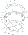
Fig. 1 is a first view of an auxiliary support assembly of a support device of a jacking beam body provided in the present invention;
FIG. 2 is a second view of the auxiliary support assembly of the support apparatus of the jacking beam body provided in the present invention;
fig. 3 is a first connection schematic diagram of two adjacent auxiliary support assemblies of the support device of the jacking beam body provided by the invention;
FIG. 4 is a second connection diagram of two adjacent auxiliary support assemblies of the support device of the jacking beam body provided by the invention;
FIG. 5 is a flow chart of a construction method of a jacking beam body provided by the present invention;
fig. 6 is a schematic structural view of step S1 in the construction method of the jacking beam body according to the present invention;
fig. 7 is a schematic structural view of step S2 in the construction method of the jacking beam body according to the present invention;
fig. 8 is a schematic structural view of step S3 in the construction method of the jacking beam body according to the present invention;
fig. 9 is a schematic structural view of step S4 in the construction method of the jacking beam body according to the present invention;
fig. 10 is a schematic structural view of step S5 in the construction method of the jacking beam body according to the present invention;
fig. 11 is a schematic structural view of the jacking beam body in the construction method of the jacking beam body provided by the invention when the jack is fixed with the bearing beam.
In the figure:
100-a beam body; 101-a spandrel girder; 102-T beam;
1-a jack; 2-an auxiliary support assembly;
11-a top rod;
21-a load-bearing tube; 22-upper connecting piece; 23-lower connector; 24-a reinforcement assembly; 25-a fastener; 26-a stop nut;
222-a connection hole;
241-a support mandrel; 242-stiffening ribs;
2421-chamfering.
Detailed Description
The present invention will be described in further detail with reference to the accompanying drawings and examples. It is to be understood that the specific embodiments described herein are merely illustrative of the invention and are not limiting of the invention. It should be further noted that, for the convenience of description, only some of the structures related to the present invention are shown in the drawings, not all of the structures.
In the description of the present invention, unless expressly stated or limited otherwise, the terms "connected," "connected," and "fixed" are to be construed broadly, e.g., as meaning permanently connected, removably connected, or integral to one another; can be mechanically or electrically connected; either directly or indirectly through intervening media, either internally or in any other relationship. The specific meanings of the above terms in the present invention can be understood in specific cases to those skilled in the art.
In the present invention, unless otherwise expressly stated or limited, "above" or "below" a first feature means that the first and second features are in direct contact, or that the first and second features are not in direct contact but are in contact with each other via another feature therebetween. Also, the first feature being "on," "above" and "over" the second feature includes the first feature being directly on and obliquely above the second feature, or merely indicating that the first feature is at a higher level than the second feature. A first feature being "under," "below," and "beneath" a second feature includes the first feature being directly under and obliquely below the second feature, or simply meaning that the first feature is at a lesser elevation than the second feature.
In the description of the present embodiment, the terms "upper", "lower", "left", "right", and the like are used based on the orientations and positional relationships shown in the drawings only for convenience of description and simplification of operation, and do not indicate or imply that the referred device or element must have a specific orientation, be configured and operated in a specific orientation, and thus, should not be construed as limiting the present invention. Furthermore, the terms "first" and "second" are used only for descriptive purposes and are not intended to have a special meaning.
As shown in fig. 1 to 4, the present embodiment provides a supporting device for jacking a beam body, a jack 1 is provided at the bottom of the beam body 100, and a top rod 11 of the jack 1 can abut against the beam body 100 for jacking the beam body 100. A plurality of auxiliary supporting components 2 which are stacked in sequence from bottom to top are arranged below the beam body 100 and below the jack 1. The auxiliary support assembly 2 comprises a load bearing tube 21, an upper connector 22, a lower connector 23 and a reinforcement assembly 24.
The upper and lower connecting members 22 and 23 are arranged at intervals in the circumferential direction of the bearing pipe 21. When the beam body 100 is jacked up, two adjacent auxiliary support assemblies 2 are detachably connected through the upper connecting piece 22 and the lower connecting piece 23 which are close to each other. After the jacking operation is completed, the stacked auxiliary supporting components 2 can be detached to be repeatedly used, and the turnover frequency is increased. By arranging the upper connecting piece 22 and the lower connecting piece 23, the contact area between two adjacent auxiliary supporting assemblies 2 can be increased, and the supporting stability when the beam body 100 is jacked up is improved. Through setting up hollow bearing pipe 21, when guaranteeing to support intensity, can reduce the material quantity, save construction cost, and can effectively reduce auxiliary stay subassembly 2's weight, make things convenient for constructor on-the-spot transport and installation. The reinforcing assembly 24 is disposed inside the load bearing tube 21. The reinforcing component 24 includes a supporting mandrel 241 and a plurality of stiffening rib plates 242 arranged at intervals in the circumferential direction of the supporting mandrel 241, one end of each stiffening rib plate 242 is connected with the supporting mandrel 241, and the other end of each stiffening rib plate 242 is connected with the inner wall of the bearing pipe 21, so as to avoid the hollow inside of the bearing pipe 21, effectively improve the supporting strength of the bearing pipe 21, and prevent the bearing pipe 21 from being deformed greatly when supporting the beam body 100, so as to cause the beam body 100 to tilt or even collapse.
Referring to fig. 3 and 4, in order to realize the detachable connection of two adjacent auxiliary support assemblies 2, optionally, the lower connecting piece 23 of the upper auxiliary support assembly 2 and the upper connecting piece 22 of the lower auxiliary support assembly 2 are fixedly connected through a fastener 25 and a stop nut 26. The fastening member 25 passes through the lower connecting member 23 of the upper auxiliary support assembly 2 and the upper connecting member 22 of the lower auxiliary support assembly 2 in sequence, and is threadedly coupled to the stopper nut 26. The threaded connection is stable and firm, the failure is not easy to occur, the disassembly is convenient, and the repeated utilization can be realized.
With continued reference to fig. 3 and 4, the fastener 25 is provided in plurality. A plurality of fasteners 25 are uniformly distributed circumferentially around the bearing pipe 21, and each fastener 25 penetrates through the lower connecting member 23 of the upper auxiliary support assembly 2 and the upper connecting member 22 of the lower auxiliary support assembly 2 and is in threaded connection with a corresponding stop nut 26. Through setting up a plurality of fasteners 25, can improve the joint strength between two adjacent auxiliary stay subassemblies 2, avoid becoming flexible or dislocation. The fasteners 25 are evenly distributed on the outer side of the bearing tube 21, so that the two connecting pieces connected with each other are evenly stressed. In the present embodiment, for example, eight fasteners 25 are uniformly distributed on two connected connecting members, so that the connecting strength and stability can be fully ensured. Of course, in other embodiments, the number and distribution of the fasteners 25 may be specifically selected according to the weight of the beam 100, construction requirements, and the like, and are not particularly limited herein.
Preferably, the fastener 25 comprises a bolt, the material is convenient to obtain, the manufacturing cost is low, and the engineering cost can be reduced. A plurality of connecting holes 222 are correspondingly arranged on the lower connecting piece 23 of the upper auxiliary supporting component 2 and the upper connecting piece 22 of the lower auxiliary supporting component 2 one by one, and bolts sequentially penetrate through the two opposite connecting holes 222 and are in threaded connection with the stop nuts 26.
Referring to fig. 1 and 2, optionally, the upper connector 22 includes a first flange. The inner wall of the first flange plate is welded with the outer wall of the bearing pipe 21, and the top surface of the first flange plate is flush with the top surface of the bearing pipe 21. The lower connector 23 comprises a second flange. The inner wall of the second flange plate is welded with the outer wall of the bearing pipe 21, and the bottom surface of the second flange plate is flush with the bottom surface of the bearing pipe 21. Further, the top surface of the reinforcing rib 242 is flush with the top surface of the load-bearing pipe 21, and the bottom surface of the reinforcing rib 242 is flush with the bottom surface of the load-bearing pipe 21. That is, in this embodiment, the top surfaces of the first flange plate, the bearing pipe 21 and the stiffening rib plate 242 are all flush with each other, and the bottom surfaces of the second flange plate, the bearing pipe 21 and the stiffening rib plate 242 are all flush with each other, so that the bearing area of the auxiliary supporting assembly 2 can be increased by the arrangement method, and the supporting stability of the auxiliary supporting assembly 2 in the jacking operation of the beam body 100 is effectively improved.
With continued reference to fig. 1 and 2, optionally, the end of the stiffening rib 242 connected to the support mandrel 241 and the end of the stiffening rib 242 connected to the inner wall of the bearing tube 21 are provided with chamfers 2421. Specifically, the stiffening rib 242 is a square plate. The four corners of the square plate are provided with chamfers 2421. The both ends of square board are connected with the outer wall of supporting mandrel 241 and the inner wall of bearing pipe 21 respectively, and the corner cut is located the edge of hookup location, can effectively avoid stress concentration, prevents that stiffening rib plate 242 and bearing pipe 21 from damaging at the excessive speed.
Furthermore, the stiffening rib plates 242 are welded with the outer wall of the support mandrel 241 and the inner wall of the bearing pipe 21, so that the operation is convenient, the connection is stable, and the deformation caused by failure is not easy to occur.
Optionally, the outer wall of the bearing pipe 21 is also provided with a lifting lug (not shown). When jacking operation is carried out on the beam body 100, the auxiliary support assemblies 2 can be hoisted to the position near a construction site through hoisting equipment. The lifting hook of the lifting device is hooked in the lifting eye, so that the whole auxiliary support assembly 2 is lifted off the ground and transported to a designated position. Of course, the transport process after the production of the support tube 21 can also be carried out by means of a lifting device.
Optionally, an indication structure (not shown) is disposed on each of the upper connecting member 22 and the lower connecting member 23 to improve the installation efficiency of two adjacent auxiliary support assemblies 2. During installation, the lower connecting piece 23 of the upper auxiliary supporting assembly 2 is attached to the upper connecting piece 22 of the lower auxiliary supporting assembly 2, the indicating structures on the two connecting pieces are just opposite to each other, at the moment, the connecting holes 222 on the two connecting pieces are just opposite to each other one by one, and the two connecting pieces are conveniently connected through the fastening piece 25 subsequently. When piling up top auxiliary stay subassembly 2 on below auxiliary stay subassembly 2, only need guarantee to instruct the structure to adjust well, can realize that connecting hole 222 on two connecting pieces is just right, convenient operation effectively improves the efficiency of construction.
Preferably, in this embodiment, the bearing pipe 21, the upper connecting member 22, the lower connecting member 23 and the reinforcing member 24 are made of Q235 steel, and have high strength. The bolts connecting the adjacent two auxiliary support assemblies 2 can be directly purchased as finished products.
In this embodiment, the first flange plate and the second flange plate are both made of steel plates with a thickness of 12mm, and eight connecting holes 222 with a diameter of 23mm are uniformly formed in the two flange plates at an interval of 45 degrees. The support mandrel 241 is made of round steel with a diameter of 3 cm. Four stiffening rib plates 242 with the size of 30cm multiplied by 12cm multiplied by 1.2cm are evenly distributed on the circumference. The adopted bolt is an M20 high-strength bolt, so that the connection strength is ensured. The bearing pipe 21 is made of a steel pipe with the diameter of 30cm and the thickness of 1cm, and the height of the bearing pipe 21 can be set according to the jacking height of the concrete beam body 100, and is generally 5cm, 10cm and 20 cm. The whole auxiliary supporting component 2 made by the method has light weight and small volume, and can be carried and installed manually. And the material consumption is little during the preparation, and processing is convenient, and reuse rate is high, and economic nature is better.
In the present embodiment, the jack 1 is preferably a hydraulic jack. The hydraulic jack has the advantages of large thrust, high jacking efficiency, uniform and stable motion and stable jacking speed, and can ensure the safety of the jacking beam body 100 in the process. In addition, the hydraulic jack is easy to realize automation, complex automatic working circulation can be easily realized by means of various control valves, particularly when hydraulic control and electric control are combined for use, and remote control can be realized.
Further, the hydraulic jack is electrically connected with the PCL circuit. The PCL circuit can control the hydraulic jack to lift and retract, and the operation is convenient and fast. In addition, a plurality of hydraulic jacks are provided at the bottom of the girder 100 to provide a sufficient jacking force to the girder 100. Through a plurality of hydraulic jack of PCL circuit control, can guarantee a plurality of hydraulic jack's the on-off time, jacking speed is unanimous to make a plurality of hydraulic jack's jacking height in same time quantum unanimous.
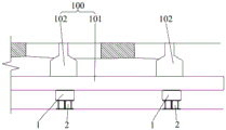
As shown in fig. 5, the present embodiment further provides a construction method of a jacking beam body, where the construction is performed by using the supporting device of the jacking beam body, and the beam body 100 includes a bearing beam 101 and a plurality of T-beams 102 disposed above the bearing beam 101 at intervals. The jack 1 and the auxiliary supporting component 2 are arranged below the bearing beam 101. The concrete construction steps are as follows:
step S1: referring to fig. 6, a jack 1 and an auxiliary support assembly 2 are disposed below a load beam 101. An auxiliary supporting component 2 is correspondingly arranged below each jack 1. The jack 1 is placed on the corresponding auxiliary supporting component 2, and the top rod 11 of the jack 1 is abutted to the bottom of the bearing beam 101;
step S2: referring to fig. 7, the top bar 11 of the jack 1 is driven to lift the beam body 100 until the top bar 11 of the jack 1 finishes a stroke;
step S3: referring to fig. 8, the auxiliary support assembly 2 is filled in a gap below the load beam 101 to support the entire beam body 100. Specifically, a plurality of auxiliary supporting assemblies 2 are arranged on both sides of each jack 1 to support the beam body 100;
step S4: referring to fig. 9, the jack 1 returns to the top retraction state, and the jack 1 is taken out from the lower part of the bearing beam 101, so as to enter the top reversing operation stage;
step S5: referring to fig. 10, after the jack 1 is taken out, the auxiliary supporting component 2 is stuffed at the position of the original jack 1, and the jack 1 is dropped on the stuffed auxiliary supporting component 2 to heighten the jack 1;
step S6: and repeating the steps S2 to S5 until the beam body 100 is jacked to the set position.
It should be noted that, in this embodiment, the cylinder body of the jack 1 is placed on the auxiliary supporting assembly 2, and the top rod 11 of the jack 1 contacts with the bottom surface of the bearing beam 101 to lift the whole beam body 100. In the stage of the reverse jacking operation, the jack 1 is taken out from the bottom of the bearing beam 101, and the auxiliary supporting assembly 2 is stacked at the position of the original jack 1 to raise the jack 1 continuously, so that the beam body 100 is jacked to a set height continuously to meet the requirement of long-stroke jacking.
However, in other embodiments of the present invention, the jack 1 may be inverted, and multiple raising and jacking of the beam 100 may also be implemented. Specifically, in step S1, the cylinder of the jack 1 is fixedly connected to the bottom of the load-bearing beam 101, and the top rod 11 of the jack 1 abuts on the auxiliary support assembly 2 below the jack 1.
Optionally, the cylinder body of the jack 1 is symmetrically provided with two lifting rings, and the bottom of the bearing beam 101 is provided with a lifting hole. The steel wire rope sequentially passes through a hanging ring of the jack 1 and a hanging hole of the bearing beam 101 so as to fix the jack 1 at the bottom of the bearing beam 101. Of course, the cylinder of the jack 1 may be fixed to the load beam 101 by other means. Further, a steel plate is stacked on the auxiliary supporting component 2 below the jack 1, and the ejector rod 11 of the jack 1 abuts against the steel plate so as to increase the contact area between the ejector rod 11 and the auxiliary supporting component 2 and avoid stress concentration.
When the ram 11 of the jack 1 is driven to extend out of the cylinder, the cylinder moves upward relative to the ram 11, and the beam 100 is lifted accordingly. After the mandril 11 extends out to the extreme position, the auxiliary supporting components 2 are arranged on two sides of the jack 1 so as to carry out the inverted jacking operation. Subsequently, the jack 1 is driven to return to the top, and the jack 1 after the top return is hung at the bottom of the bearing beam 101 because the cylinder body is fixed at the bottom of the bearing beam 101, as shown in fig. 11. And moving out the steel plate, stacking a new auxiliary supporting component 2, placing the steel plate on the newly stacked auxiliary supporting component 2, driving the jack 1 to be in contact with the steel plate again and jacking the beam body 100 until the beam body 100 is jacked to a set position. Through inverting jack 1, can hang in the bottom of spandrel girder 101 when jack 1 returns the oil and contracts the top, only need in the clearance of jack 1 below fill in the auxiliary stay subassembly 2 can, need not to take out jack 1 from the below of spandrel girder 101 again and stack auxiliary stay subassembly 2, simplify the construction process, improve jacking efficiency.
According to the construction method for jacking the beam body, the beam body 100 can be jacked to a set height through multiple jacking and gradual heightening of the filling auxiliary support assembly 2, and the jacking process of the beam body 100 is rapidly, efficiently and safely completed.
It should be understood that the above-described embodiments of the present invention are merely examples for clearly illustrating the present invention, and are not intended to limit the embodiments of the present invention. Numerous obvious variations, adaptations and substitutions will occur to those skilled in the art without departing from the scope of the invention. And are neither required nor exhaustive of all embodiments. Any modification, equivalent replacement, and improvement made within the spirit and principle of the present invention should be included in the protection scope of the claims of the present invention.
Claims (10)
1. The utility model provides a strutting arrangement of jacking roof beam body, is including being used for the jacking jack (1) of roof beam body (100), ejector pin (11) of jack (1) can with roof beam body (100) butt, a serial communication port, the below of jack (1) and the below of roof beam body (100) all is provided with a plurality of auxiliary stay subassemblies (2) that stack in proper order, auxiliary stay subassembly (2) include:
a bearing tube (21);
the auxiliary support assembly comprises an upper connecting piece (22) and a lower connecting piece (23), wherein the upper connecting piece (22) and the lower connecting piece (23) are arranged at intervals along the axial direction of the bearing pipe (21), and two adjacent auxiliary support assemblies (2) are detachably connected through the upper connecting piece (22) and the lower connecting piece (23) which are close to each other;
strengthen subassembly (24), be located bearing pipe (21), strengthen subassembly (24) including support dabber (241) and a plurality of stiffening rib board (242), it is a plurality of stiffening rib board (242) are followed the circumference interval of support dabber (241) sets up, stiffening rib board (242) are kept away from the one end of support dabber (241) connect in the inner wall of bearing pipe (21).
2. The supporting device of the jacking beam body as claimed in claim 1, wherein the auxiliary supporting assembly (2) further comprises a fastening member (25) and a stop nut (26), the fastening member (25) sequentially penetrates through an upper connecting member (22) and a lower connecting member (23) which are close to each other in two adjacent auxiliary supporting assemblies (2) and is connected with the stop nut (26).
3. The supporting device for the jacking beam body according to claim 2, wherein the fastening member (25) is provided in plurality, and the plurality of fastening members (25) are circumferentially and uniformly distributed around the bearing pipe (21).
4. The support device of a jacking beam body as claimed in claim 2, wherein said fastener (25) comprises a bolt.
5. The support device for the jacking beam body according to claim 1, wherein the upper connecting member (22) comprises a first flange, the inner wall of the first flange is connected with the outer wall of the bearing pipe (21), and the top surface of the first flange is flush with the top surface of the bearing pipe (21);
the lower connecting piece (23) comprises a second flange plate, the inner wall of the second flange plate is connected with the outer wall of the bearing pipe (21), and the bottom surface of the second flange plate is flush with the bottom surface of the bearing pipe (21).
6. The support device for the jacking beam body according to claim 5, wherein the top surface of the stiffening rib (242) is flush with the top surface of the bearing pipe (21), and the bottom surface of the stiffening rib (242) is flush with the bottom surface of the bearing pipe (21).
7. The supporting device of the jacking beam body according to any one of claims 1 to 6, wherein one end of the stiffening rib plate (242) connected with the supporting mandrel (241) and one end of the stiffening rib plate (242) connected with the inner wall of the bearing pipe (21) are provided with chamfers (2421).
8. Support device for a jacking beam according to any one of claims 1 to 6, wherein said jack (1) is a hydraulic jack.
9. Support device for a jacking beam according to any one of claims 1 to 6, wherein the outer wall of said bearing pipe (21) is provided with lifting lugs configured as a hook for hooking a lifting apparatus.
10. A construction method of a supporting device for a jacking beam body according to any one of claims 1 to 9, comprising the steps of:
step S1: a jack (1) and an auxiliary supporting component (2) are arranged below the beam body (100), the jack (1) is placed on the auxiliary supporting component (2), and a top rod (11) of the jack (1) is abutted to the bottom surface of the beam body (100);
step S2: a top rod (11) of the driving jack (1) jacks the beam body (100);
step S3: filling an auxiliary support assembly (2) in a gap below the beam body (100) to support the beam body (100);
step S4: the jack (1) returns to the oil retraction jack, and the jack (1) is taken out from the lower part of the beam body (100);
step S5: after the jack (1) is taken out, filling an auxiliary supporting component (2) at the position of the original jack (1), and dropping the jack (1) on the filled auxiliary supporting component (2) to heighten the jack (1);
step S6: and repeating the steps S2 to S5 until the beam body (100) is jacked to the set position.
Priority Applications (1)
| Application Number | Priority Date | Filing Date | Title |
|---|---|---|---|
| CN202110361626.5A CN112878214A (en) | 2021-04-02 | 2021-04-02 | Supporting device for jacking beam body and construction method |
Applications Claiming Priority (1)
| Application Number | Priority Date | Filing Date | Title |
|---|---|---|---|
| CN202110361626.5A CN112878214A (en) | 2021-04-02 | 2021-04-02 | Supporting device for jacking beam body and construction method |
Publications (1)
| Publication Number | Publication Date |
|---|---|
| CN112878214A true CN112878214A (en) | 2021-06-01 |
Family
ID=76040471
Family Applications (1)
| Application Number | Title | Priority Date | Filing Date |
|---|---|---|---|
| CN202110361626.5A Pending CN112878214A (en) | 2021-04-02 | 2021-04-02 | Supporting device for jacking beam body and construction method |
Country Status (1)
| Country | Link |
|---|---|
| CN (1) | CN112878214A (en) |
Cited By (1)
| Publication number | Priority date | Publication date | Assignee | Title |
|---|---|---|---|---|
| CN116240826A (en) * | 2023-05-06 | 2023-06-09 | 四川省公路规划勘察设计研究院有限公司 | Reset pushing system and deviation correcting method thereof |
-
2021
- 2021-04-02 CN CN202110361626.5A patent/CN112878214A/en active Pending
Cited By (1)
| Publication number | Priority date | Publication date | Assignee | Title |
|---|---|---|---|---|
| CN116240826A (en) * | 2023-05-06 | 2023-06-09 | 四川省公路规划勘察设计研究院有限公司 | Reset pushing system and deviation correcting method thereof |
Similar Documents
| Publication | Publication Date | Title |
|---|---|---|
| CN101987651B (en) | Assembling method and assembling bracket of total segments of small ship | |
| CN103243930A (en) | System and method for modularized construction of super high-rise steel structures | |
| CN214883051U (en) | Supporting device of jacking beam body | |
| CN106988299B (en) | The pay-off method of assembled steel reinforced cage descending frame and steel reinforcement cage | |
| CN112878214A (en) | Supporting device for jacking beam body and construction method | |
| CN107471427B (en) | Construction method of prefabricated hollow floor slab | |
| CN208732495U (en) | A kind of small gun carriage | |
| CN109487789B (en) | Multi-cylinder self-balancing lifting method for pile frame of ocean pile driving barge | |
| CN205500636U (en) | Water conservancy project component handling device | |
| CN214692858U (en) | Floor transportation frock | |
| CN209799360U (en) | combined movable steel formwork | |
| CN210482577U (en) | A prop up top circulation system for three-dimensional prefabricated full assembled concrete structure | |
| CN210308361U (en) | Self-contraction type inner formwork structure for caisson prefabrication | |
| CN113738156A (en) | Temporary support structure in limited space and dismantling method thereof | |
| CN207209840U (en) | A kind of Multifunctional suspension bracket | |
| CN220810162U (en) | Integral carrying device for heavy goods shelf | |
| CN218595993U (en) | Offshore platform hoisting system | |
| CN215052142U (en) | Continuous tensioning lifting beam device | |
| CN203903792U (en) | Gantry frame for placing equipment | |
| CN212425121U (en) | Balance beam hoisting device | |
| CN216863407U (en) | Turnover type portal frame | |
| CN218757028U (en) | Temporary buttress structure and approach bridge | |
| CN217555563U (en) | Hoisting equipment for hoisting heavy equipment | |
| CN216155398U (en) | Water tank lifting construction device of inverted cone water tower | |
| CN220618076U (en) | Superimposed sheet transportation, hoist device |
Legal Events
| Date | Code | Title | Description |
|---|---|---|---|
| PB01 | Publication | ||
| PB01 | Publication | ||
| SE01 | Entry into force of request for substantive examination | ||
| SE01 | Entry into force of request for substantive examination |