CN112873417A - Efficient and stable precision slitting equipment and working method thereof - Google Patents
Efficient and stable precision slitting equipment and working method thereof Download PDFInfo
- Publication number
- CN112873417A CN112873417A CN202011571298.3A CN202011571298A CN112873417A CN 112873417 A CN112873417 A CN 112873417A CN 202011571298 A CN202011571298 A CN 202011571298A CN 112873417 A CN112873417 A CN 112873417A
- Authority
- CN
- China
- Prior art keywords
- roller
- winding
- shaft
- guide roller
- unwinding
- Prior art date
- Legal status (The legal status is an assumption and is not a legal conclusion. Google has not performed a legal analysis and makes no representation as to the accuracy of the status listed.)
- Pending
Links
- 238000000034 method Methods 0.000 title claims abstract description 23
- 238000004804 winding Methods 0.000 claims abstract description 217
- 230000007246 mechanism Effects 0.000 claims abstract description 113
- 238000007723 die pressing method Methods 0.000 claims abstract description 56
- 238000005096 rolling process Methods 0.000 claims abstract description 35
- 239000000463 material Substances 0.000 claims abstract description 32
- 230000005540 biological transmission Effects 0.000 claims description 134
- 230000007704 transition Effects 0.000 claims description 24
- 238000007774 anilox coating Methods 0.000 claims description 13
- 238000006073 displacement reaction Methods 0.000 claims description 12
- 230000006835 compression Effects 0.000 claims description 8
- 238000007906 compression Methods 0.000 claims description 8
- 238000004519 manufacturing process Methods 0.000 abstract description 6
- 230000008569 process Effects 0.000 abstract description 6
- 229920002799 BoPET Polymers 0.000 abstract description 5
- 238000004026 adhesive bonding Methods 0.000 abstract description 2
- 210000002469 basement membrane Anatomy 0.000 abstract 1
- 238000005520 cutting process Methods 0.000 description 8
- 238000000926 separation method Methods 0.000 description 4
- 239000003292 glue Substances 0.000 description 3
- 230000007547 defect Effects 0.000 description 2
- 230000000694 effects Effects 0.000 description 2
- 239000012528 membrane Substances 0.000 description 2
- 238000012986 modification Methods 0.000 description 2
- 230000004048 modification Effects 0.000 description 2
- 238000003825 pressing Methods 0.000 description 2
- 230000001360 synchronised effect Effects 0.000 description 2
- RYGMFSIKBFXOCR-UHFFFAOYSA-N Copper Chemical compound [Cu] RYGMFSIKBFXOCR-UHFFFAOYSA-N 0.000 description 1
- 229910000831 Steel Inorganic materials 0.000 description 1
- XAGFODPZIPBFFR-UHFFFAOYSA-N aluminium Chemical compound [Al] XAGFODPZIPBFFR-UHFFFAOYSA-N 0.000 description 1
- 229910052782 aluminium Inorganic materials 0.000 description 1
- 230000009286 beneficial effect Effects 0.000 description 1
- 230000008859 change Effects 0.000 description 1
- 238000010276 construction Methods 0.000 description 1
- 239000011889 copper foil Substances 0.000 description 1
- 238000007599 discharging Methods 0.000 description 1
- 239000011888 foil Substances 0.000 description 1
- 230000006872 improvement Effects 0.000 description 1
- 238000009434 installation Methods 0.000 description 1
- 239000010959 steel Substances 0.000 description 1
Images


Classifications
-
- B—PERFORMING OPERATIONS; TRANSPORTING
- B26—HAND CUTTING TOOLS; CUTTING; SEVERING
- B26F—PERFORATING; PUNCHING; CUTTING-OUT; STAMPING-OUT; SEVERING BY MEANS OTHER THAN CUTTING
- B26F1/00—Perforating; Punching; Cutting-out; Stamping-out; Apparatus therefor
- B26F1/38—Cutting-out; Stamping-out
- B26F1/40—Cutting-out; Stamping-out using a press, e.g. of the ram type
- B26F1/42—Cutting-out; Stamping-out using a press, e.g. of the ram type having a pressure roller
-
- B—PERFORMING OPERATIONS; TRANSPORTING
- B26—HAND CUTTING TOOLS; CUTTING; SEVERING
- B26D—CUTTING; DETAILS COMMON TO MACHINES FOR PERFORATING, PUNCHING, CUTTING-OUT, STAMPING-OUT OR SEVERING
- B26D7/00—Details of apparatus for cutting, cutting-out, stamping-out, punching, perforating, or severing by means other than cutting
- B26D7/27—Means for performing other operations combined with cutting
- B26D7/32—Means for performing other operations combined with cutting for conveying or stacking cut product
-
- B—PERFORMING OPERATIONS; TRANSPORTING
- B65—CONVEYING; PACKING; STORING; HANDLING THIN OR FILAMENTARY MATERIAL
- B65H—HANDLING THIN OR FILAMENTARY MATERIAL, e.g. SHEETS, WEBS, CABLES
- B65H16/00—Unwinding, paying-out webs
- B65H16/02—Supporting web roll
- B65H16/021—Multiple web roll supports
-
- B—PERFORMING OPERATIONS; TRANSPORTING
- B65—CONVEYING; PACKING; STORING; HANDLING THIN OR FILAMENTARY MATERIAL
- B65H—HANDLING THIN OR FILAMENTARY MATERIAL, e.g. SHEETS, WEBS, CABLES
- B65H18/00—Winding webs
- B65H18/02—Supporting web roll
- B65H18/021—Multiple web roll supports
-
- B—PERFORMING OPERATIONS; TRANSPORTING
- B65—CONVEYING; PACKING; STORING; HANDLING THIN OR FILAMENTARY MATERIAL
- B65H—HANDLING THIN OR FILAMENTARY MATERIAL, e.g. SHEETS, WEBS, CABLES
- B65H18/00—Winding webs
- B65H18/02—Supporting web roll
- B65H18/026—Cantilever type
-
- B—PERFORMING OPERATIONS; TRANSPORTING
- B65—CONVEYING; PACKING; STORING; HANDLING THIN OR FILAMENTARY MATERIAL
- B65H—HANDLING THIN OR FILAMENTARY MATERIAL, e.g. SHEETS, WEBS, CABLES
- B65H18/00—Winding webs
- B65H18/08—Web-winding mechanisms
- B65H18/10—Mechanisms in which power is applied to web-roll spindle
- B65H18/103—Reel-to-reel type web winding and unwinding mechanisms
-
- B—PERFORMING OPERATIONS; TRANSPORTING
- B65—CONVEYING; PACKING; STORING; HANDLING THIN OR FILAMENTARY MATERIAL
- B65H—HANDLING THIN OR FILAMENTARY MATERIAL, e.g. SHEETS, WEBS, CABLES
- B65H20/00—Advancing webs
- B65H20/02—Advancing webs by friction roller
-
- B—PERFORMING OPERATIONS; TRANSPORTING
- B65—CONVEYING; PACKING; STORING; HANDLING THIN OR FILAMENTARY MATERIAL
- B65H—HANDLING THIN OR FILAMENTARY MATERIAL, e.g. SHEETS, WEBS, CABLES
- B65H35/00—Delivering articles from cutting or line-perforating machines; Article or web delivery apparatus incorporating cutting or line-perforating devices, e.g. adhesive tape dispensers
- B65H35/02—Delivering articles from cutting or line-perforating machines; Article or web delivery apparatus incorporating cutting or line-perforating devices, e.g. adhesive tape dispensers from or with longitudinal slitters or perforators
-
- B—PERFORMING OPERATIONS; TRANSPORTING
- B26—HAND CUTTING TOOLS; CUTTING; SEVERING
- B26D—CUTTING; DETAILS COMMON TO MACHINES FOR PERFORATING, PUNCHING, CUTTING-OUT, STAMPING-OUT OR SEVERING
- B26D7/00—Details of apparatus for cutting, cutting-out, stamping-out, punching, perforating, or severing by means other than cutting
- B26D7/27—Means for performing other operations combined with cutting
- B26D7/32—Means for performing other operations combined with cutting for conveying or stacking cut product
- B26D2007/322—Means for performing other operations combined with cutting for conveying or stacking cut product the cut products being sheets, e.g. sheets of paper
-
- B—PERFORMING OPERATIONS; TRANSPORTING
- B65—CONVEYING; PACKING; STORING; HANDLING THIN OR FILAMENTARY MATERIAL
- B65H—HANDLING THIN OR FILAMENTARY MATERIAL, e.g. SHEETS, WEBS, CABLES
- B65H2701/00—Handled material; Storage means
- B65H2701/10—Handled articles or webs
- B65H2701/19—Specific article or web
Abstract
The invention discloses an efficient and stable precision slitting device, which comprises: the device comprises a fixed seat, a main unwinding mechanism, a middle guide roller, a bottom cutter traction roller, an upper die pressing cutter roller, a four-station shaft changing winding mechanism, a bottom film supporting unwinding mechanism and an edge material winding mechanism, wherein the fixed seat is provided with the upper die pressing cutter roller and the bottom cutter traction roller in a matching manner; the bottom of the drag roll of the bed knife is provided with a bottom supporting film winding and unwinding mechanism and an edge material winding and unwinding mechanism; the working method of the efficient and stable precision slitting equipment is also included; adopt the PET film to do the support basement membrane on the one hand, utilize film tension to assist the cutter to cut, can not overflow the adhesion of gluing, reduced the process, improved production quality and efficiency, on the other hand has improved the rolling structure, has realized the rolling of two biax groups, need not shut down the unloading, and production speed is fast.
Description
Technical Field
The invention belongs to the technical field of splitting machines and particularly relates to efficient and stable precision splitting equipment and a working method thereof.
Background
The slitting machine is an indispensable tool in the industry, and the slitting machine can be used for longitudinally slitting materials and then winding the slit materials into a disc, is widely applied to the industries of paper, films, copper foils, aluminum foils, steel belts and the like, and can meet different process requirements. The work efficiency of slitting machine is deciding the finished product quality, and whether the slitting machine quality is outstanding depends on the speed of equipment, product percent of pass, controllability, stability and other aspects indexes. In the traditional slitting work, the cutter installation and calibration, the loading and the unloading are quite time-consuming, and operators without certain practical experience cannot drive the cutter. This results in low work efficiency, increased defect rate, and increased cost, and thus the improvement of the equipment process is not slow.
When cutting viscidity product, the most problem that has the excessive adhesion of gluing of present equipment of cutting, the phenomenon of mutual adhesion can appear in the finished product, need separate the parcel from type paper, and the process is complicated, the processing effect is poor, and simultaneously, present equipment of cutting mostly has the slow problem of process velocity, because the cutting machine commonly used need shut down the unloading or change the rolling axle, production efficiency is slow. Therefore, the present application has innovated and improved the slicer with regard to the above problems.
The existing slitting equipment mainly has the following problems:
1. most existing slitting equipment has the problem of glue overflowing adhesion, finished products can be adhered to each other, wrapping needs to be separated from release paper, the process is complex, and the processing effect is poor.
2. The existing slitting equipment mostly has the problem of low processing speed, and the production efficiency is low because the commonly used slitting machine needs to stop discharging or replace a winding shaft.
Disclosure of Invention
The purpose of the invention is as follows: in order to overcome the defects, the invention aims to provide efficient and stable precision slitting equipment and a working method thereof.
The technical scheme is as follows: in order to achieve the above object, the present invention provides an efficient stable precision slitting apparatus, comprising: the device comprises a fixed seat, a main unwinding mechanism, a middle guide roller, a bottom cutter traction roller, an upper die pressing cutter roller, a four-station shaft changing winding mechanism, a bottom supporting film winding and unwinding mechanism and an edge material winding mechanism, wherein the fixed seat is provided with the upper die pressing cutter roller; a bottom knife traction roller is arranged at the bottom of the upper die pressing knife roller, the bottom knife traction roller is connected with the upper die pressing knife roller in a matched mode through a gear, and a bottom film supporting and unwinding mechanism is arranged at the bottom of the bottom knife traction roller; and one side of the supporting film winding and unwinding mechanism is provided with a rim charge winding mechanism.
According to the invention, the arrangement of the cutting equipment adopts the PET film as the supporting film, the film tension is utilized to assist the cutter to cut, the separation distance is large, the separation surface is smooth, the cutter is not in contact with the traction roller of the bed knife, the cutter and the equipment are protected, glue overflow adhesion is avoided, and the product is not required to be isolated by release paper, so that the working procedures are reduced, the time and the labor are saved, the product quality is improved, and the cost is reduced.
According to the arrangement of the upper die pressing knife roller, a die pressing circular knife is adopted as a knife, a group of circular traction supporting rollers and a servo motor are arranged below the circular knife and used for power transmission, and the die pressing circular knife and the traction supporting rollers transmit power up and down by using gears, so that the specification of the die pressing circular knife is convenient to replace.
The upper die pressing knife roller comprises a cutting edge arranged in the center, and the roller diameters of two ends of the upper die pressing knife roller are larger than the diameter of the cutting edge by 0.02 mm.
The arrangement of the upper die pressing knife roller can ensure that the knife edge cannot be damaged due to misoperation.
The bottom supporting film winding and unwinding mechanism adopts a PET film as the bottom supporting film.
According to the bottom supporting film winding and unwinding mechanism, the distance between the cutters is controlled by adjusting the upper die pressing cutter roller and the bottom cutter traction roller, the cutting point is on the rubber surface, and the bottom layer PET film only plays a supporting role, so that the bottom supporting film winding and unwinding mechanism can be repeatedly used.
The linear guide rail is arranged on the fixed seat, the linear guide rail comprises a slide rail and a displacement transmission servo, the slide rail is in sliding contact with the fixed seat, the displacement transmission servo is connected with the fixed seat through a screw rod, the slide rail is arranged on a working plane, and the displacement transmission servo is arranged on the working plane.
The arrangement of the linear guide rail improves the freedom degree of equipment.
The four-station shaft-changing winding mechanism comprises an AB shaft-changing motor, a transmission belt, a first transmission belt wheel, a first reversing seat, a second transmission belt wheel and a second reversing seat, wherein the AB shaft-changing motor is arranged on a fixed seat, the transmission belt is arranged at the output end of the AB shaft-changing motor, the transmission belt is connected with the first transmission belt wheel, and the transmission belt is connected with the second transmission belt wheel; the first reversing seat is arranged on the first transmission belt wheel and arranged on the fixed seat, and the second reversing seat is arranged on the second reversing belt wheel and arranged on the fixed seat.
The transmission belt is provided with a transition transmission wheel, the transition transmission wheel is arranged on the fixed seat, and the transition transmission wheel is arranged between the first reversing seat and the second reversing seat.
The first reversing seat comprises a rolling servo motor, a rolling transmission belt wheel, a rolling transmission shaft, a rolling shaft A, a rolling shaft B, AB shaft switching cylinder and a rolling support seat, wherein the rolling support seat is arranged on the fixing seat through a bearing, the rolling transmission shaft is arranged in the rolling support seat and is connected with the rolling support seat through a bearing, the rolling transmission belt wheel is arranged on the outer side of the rolling transmission shaft and is fixed with the rolling transmission shaft through a sleeve shaft, the rolling transmission belt wheel is connected with the rolling transmission belt, the rolling servo motor is arranged at one end, away from the rolling transmission belt wheel, of the rolling transmission belt, and the rolling servo motor is arranged on the fixing seat; one end of the winding transmission shaft is connected with a winding shaft A through a gear set, one side of the winding shaft A is provided with a winding shaft B, and the winding shaft B is matched with the winding transmission shaft through the gear set; the rolling transmission shaft other end is provided with AB axle and switches the cylinder, the AB axle switches that the cylinder is fixed to be set up on the fixing base, the AB axle switches the cylinder and passes through the bearing and connect the rolling transmission shaft.
The second reversing seat and the first reversing seat have the same structure.
According to the invention, the four-station shaft-changing winding mechanism is arranged, the winding structure is improved, four-station automatic switching winding is adopted, the winding mechanism is divided into an upper group and a lower group, servo reducing motors are adopted for synchronous switching, an AB shaft adopts an automatic clutch device, power transmission is freely switched, shutdown for blanking is not needed, and the production speed is high.
The middle guide roller comprises a first reticulate pattern anti-sticking traction roller, a transition roller, a first tension sensing guide roller, a second reticulate pattern anti-sticking traction roller and a rolling rubber compression roller, the first reticulate pattern anti-sticking traction roller is arranged on the fixing seat, the first reticulate pattern anti-sticking traction roller is arranged on one side of the main unwinding mechanism, the transition roller is arranged on one side, away from the main unwinding mechanism, of the first reticulate pattern anti-sticking traction roller, the first tension sensing guide roller is arranged on one side, away from the first reticulate pattern anti-sticking traction roller, of the transition roller, an upper die pressing cutter roller is arranged on one side, away from the first tension sensing guide roller, of the upper die pressing cutter roller, the second reticulate pattern anti-sticking traction roller is arranged on one side, away from the upper die pressing cutter roller, of the second reticulate pattern anti-sticking traction roller, and the rolling.
The rubber winding compression roller is driven by a servo motor and a ball screw.
The pressure of the rubber winding compression roller is controlled by an electric proportional valve.
The bottom supporting film winding and unwinding mechanism comprises a bottom supporting film unwinding roller, an unwinding guide roller, a second tension sensing guide roller, a third tension sensing guide roller, a winding guide roller and a bottom supporting film winding roller, the fixed seat is provided with a bottom supporting film unwinding roller, one side of the bottom supporting film unwinding roller is provided with an unwinding guide roller, a second tension sensing guide roller is arranged on one side of the unwinding guide roller, which is far away from the unwinding roller of the unwinding film, a bed knife traction roller is arranged on one side of the second tension sensing guide roller, which is far away from the unwinding guide roller, a third tension sensing guide roller is arranged on one side of the bed knife traction roller far away from the second tension sensing guide roller, one side that the third tension sensing guide roller kept away from the bed knife carry over pinch rolls is provided with the rolling guide roll, one side that the third tension sensing guide roll was kept away from to the rolling guide roll is provided with and holds in the palm end membrane wind-up roll, hold in the palm end membrane wind-up roll and set up on the fixing base.
According to the invention, the third tension sensing guide roller is arranged, and the speed of the anti-sticking traction roller is controlled by using a signal instruction fed back by the pressure sensor, so that the material is released in advance due to the deformation generated by the tension during unwinding, and the unwinding tension and the winding tension are separated from each other and are independently controllable.
The tension sensing guide roller is provided with a tension sensor, and the tension sensor can be TA 120.
The rim charge winding mechanism is provided with a tensioning device in a connecting way.
The output end of the main unwinding mechanism is provided with an ultrasonic sensor for detecting whether the material is staggered.
The arrangement of the ultrasonic sensor in the invention enables the staggered layers to be visualized, and workers can conveniently find and adjust the staggered layers in time.
The working method of the efficient and stable precision slitting equipment comprises the steps of unreeling, slitting and reeling, and specifically comprises the following steps:
the method comprises the following steps: the main unwinding mechanism discharges materials and sends the materials to the bed knife traction roller through the middle guide roller, and the bed knife unwinding and winding mechanism discharges a bed knife and sends the bed knife to the bed knife traction roller;
step two: the bottom cutter traction roller is matched with the upper die pressing cutter roller to cut materials to form two finished product materials and rim charge;
step three: the finished product material is conveyed to a four-station shaft changing and winding mechanism through a middle guide roller, the rim charge is conveyed to a rim charge winding mechanism, and the bottom supporting film is recovered to a bottom supporting film winding and unwinding mechanism;
step four: and after the station winding on the four-station shaft-changing winding mechanism is completed, the four-station shaft-changing winding mechanism continues to work after the station is rotationally changed.
The technical scheme shows that the invention has the following beneficial effects:
1. according to the efficient stable precision slitting equipment and the working method thereof, the PET film is used as the supporting film, the cutter is assisted to slit by using the film tension, the separation distance is large, the separation surface is flat, the cutter is not in contact with the traction roller of the bed knife, the cutter and the equipment are protected, glue overflow adhesion is avoided, and the product is not required to be isolated by release paper, so that the working procedures are reduced, time and labor are saved, the product quality is improved, and the cost is reduced.
2. According to the efficient stable precision slitting equipment and the working method thereof, the winding structure is improved, four-station automatic exchange winding is adopted, the precision slitting equipment is divided into an upper group and a lower group, the servo speed reducing motors are adopted for synchronous exchange, the AB shafts are provided with automatic clutch devices, power transmission is freely switched, stopping is not needed, and the production speed is high.
Drawings
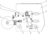
FIG. 1 is a schematic view of the overall structure of the present invention;
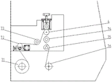
FIG. 2 is a rear view of the present invention;
FIG. 3 is a schematic structural view of a four-station shaft-changing winding mechanism according to the present invention;
FIG. 4 is a schematic structural view of a first reversing seat and a second reversing seat of the present invention;
FIG. 5 is a schematic view of the construction of the intermediate guide roller according to the present invention;
fig. 6 is a schematic structural view of a bottom supporting film winding and unwinding mechanism according to the present invention;
in the figure: a fixed seat-1, a main unreeling mechanism-2, a middle guide roller-3, a first anilox anti-sticking traction roller-31, a transition roller-32, a first pressure sensing guide roller-33, a second anilox anti-sticking traction roller-34, a reeling rubber press roller-35, a bed knife traction roller-4, an upper mould press knife roller-5, a four-station shaft-changing reeling mechanism-6, an AB shaft exchange motor-61, a transmission belt-62, a first transmission pulley-63, a first reversing seat-64, a reeling servo motor-641, a reeling transmission belt-642, a reeling transmission pulley-643, a reeling transmission shaft-644, a reeling shaft A-646, a reeling shaft B-646, an AB shaft switching cylinder-647, a reeling support-648, a second transmission pulley-65, a second reversing seat-66, a first and a second reversing seat-66, The device comprises a bottom supporting film winding and unwinding mechanism-7, a bottom supporting film winding and unwinding roller-71, a winding guide roller-72, a second tension sensing guide roller-73, a third tension sensing guide roller-74, a winding guide roller-75, a bottom supporting film winding roller-76, a rim charge winding mechanism-8 and a linear guide rail-9.
Detailed Description
The invention is further elucidated with reference to the drawings and the embodiments.
Reference will now be made in detail to embodiments of the present invention, examples of which are illustrated in the accompanying drawings, wherein like or similar reference numerals refer to the same or similar elements or elements having the same or similar function throughout. The embodiments described below with reference to the drawings are illustrative and intended to be illustrative of the invention and are not to be construed as limiting the invention.
In the description of the present invention, it is to be understood that the terms "center", "longitudinal", "lateral", "length", "width", "thickness", "upper", "lower", "front", "rear", "left", "right", "vertical", "horizontal", "top", "bottom", "inner", "clockwise", "counterclockwise", and the like, indicate orientations and positional relationships based on those shown in the drawings, and are used only for convenience of description and simplicity of description, and do not indicate or imply that the device or element being referred to must have a particular orientation, be constructed and operated in a particular orientation, and thus, are not to be considered as limiting the present invention.
Furthermore, the terms "first", "second" and "first" are used for descriptive purposes only and are not to be construed as indicating or implying relative importance or implicitly indicating the number of technical features indicated. Thus, a feature defined as "first" or "second" may explicitly or implicitly include one or more of that feature. In the description of the present invention, unless otherwise specified, "a plurality" means two or more unless explicitly defined otherwise.
In the present invention, unless otherwise expressly specified or limited, the terms "mounted," "connected," "secured," and the like are to be construed broadly and can, for example, be fixedly connected, detachably connected, or integrally connected; can be mechanically or electrically connected; they may be connected directly or indirectly through intervening media, or they may be interconnected between two elements. The specific meanings of the above terms in the present invention can be understood by those skilled in the art according to specific situations.
In the present invention, unless otherwise expressly stated or limited, "above" or "below" a first feature means that the first and second features are in direct contact, or that the first and second features are not in direct contact but are in contact with each other via another feature therebetween. Also, the first feature being "on," "above" and "over" the second feature includes the first feature being directly on and obliquely above the second feature, or merely indicating that the first feature is at a higher level than the second feature. A first feature being "under," "below," and "beneath" a second feature includes the first feature being directly under and obliquely below the second feature, or simply meaning that the first feature is at a lesser elevation than the second feature.
Example 1
An efficient and stable precision slitting apparatus as shown in fig. 1-6, comprising: the device comprises a fixed seat 1, a main unwinding mechanism 2, a middle guide roller 3, a bottom knife traction roller 4, an upper die pressing knife roller 5, a four-station shaft changing winding mechanism 6, a bottom film supporting winding and unwinding mechanism 7 and an edge material winding mechanism 8, wherein the fixed seat 1 is provided with the upper die pressing knife roller 5, the two sides of the upper die pressing knife roller 5 are provided with the middle guide rollers 3, the number of the middle guide rollers 3 is multiple, one side of each middle guide roller 3 is provided with the main unwinding mechanism 2, and the other side of each middle guide roller 3 is provided with the four-station shaft changing winding mechanism 6; a bottom knife traction roller 4 is arranged at the bottom of the upper die pressing knife roller 5, the bottom knife traction roller 4 is connected with the upper die pressing knife roller 5 through a gear in a matching way, and a bottom film supporting winding and unwinding mechanism 7 is arranged at the bottom of the bottom knife traction roller 4; and one side of the supporting film winding and unwinding mechanism 7 is provided with a rim charge winding mechanism 8.
In this embodiment, the upper die pressing knife roller 5 comprises a knife edge arranged in the center, and the roller diameters of the two ends of the upper die pressing knife roller 5 are larger than the diameter of the knife edge by 0.02 mm.
In this embodiment fixing base 1 on be provided with linear guide 9, linear guide 9 includes that slide rail and displacement transmission are servo, slide rail and 1 sliding contact of fixing base, the displacement transmission is servo to be connected through the screw rod with fixing base 1, the slide rail sets up on work plane, the displacement transmission is servo to be set up on work plane.
The four-station shaft-changing winding mechanism 6 in the embodiment comprises an AB shaft-changing motor 61, a transmission belt 62, a first transmission belt wheel 63, a first reversing seat 64, a second transmission belt wheel 65 and a second reversing seat 66, wherein the fixed seat 1 is provided with the AB shaft-changing motor 61, the output end of the AB shaft-changing motor 61 is provided with the transmission belt 62, the transmission belt 62 is connected with the first transmission belt wheel 63, and the transmission belt 62 is connected with the second transmission belt wheel 65; the first reversing seat 64 is arranged on the first transmission belt wheel 63, the first reversing seat 64 is arranged on the fixed seat 1, the second reversing seat 66 is arranged on the second reversing belt wheel 65, and the second reversing seat 66 is arranged on the fixed seat 1.
In this embodiment, the transmission belt 62 is provided with a transition transmission wheel, the transition transmission wheel is arranged on the fixed seat, and the transition transmission wheel is arranged between the first reversing seat 64 and the second reversing seat 66.
The first reversing seat 64 in this embodiment includes a winding servo motor 641, a winding transmission belt 642, a winding transmission belt 643, a winding transmission shaft 644, a winding shaft a645, a winding shaft B646, an AB shaft switching cylinder 647, and a winding support 648, the fixing seat 1 is provided with the winding support 648 through a bearing, the winding transmission shaft 644 is provided in the winding support 648, the winding transmission shaft 644 and the winding support 648 are connected through a bearing, the winding transmission belt 643 is provided outside the winding transmission shaft 644, the winding transmission belt 643 is fixed to the winding transmission shaft 644 through a sleeve shaft, the winding transmission belt 642 is connected to the winding transmission belt 643, the winding servo motor 641 is provided at one end of the winding transmission belt 642 far away from the winding transmission belt 643, and the winding servo motor 641 is provided on the fixing seat 1; one end of the winding transmission shaft 644 is connected with a winding shaft A645 through a gear set, a winding shaft B646 is arranged on one side of the winding shaft A645, and the winding shaft B646 is matched with the winding transmission shaft 644 through the gear set; an AB shaft switching cylinder 647 is arranged at the other end of the winding transmission shaft 644 and fixedly arranged on the fixing seat 1, and the AB shaft switching cylinder 647 is connected with the winding transmission shaft 644 through a bearing.
The second reversing bearing 66 in the embodiment is the same as the first reversing bearing 64.
The intermediate guide rollers 3 in the embodiment comprise a first anilox anti-sticking traction roller 31, a transition roller 32, a first tension sensing guide roller 33, a second anilox anti-sticking traction roller 34 and a rolling rubber press roller 35, a first reticulate pattern anti-sticking traction roller 31 is arranged on the fixed seat 1, the first reticulate pattern anti-sticking traction roller 31 is arranged on one side of the main unreeling mechanism 2, a transition roller 32 is arranged on one side of the first anilox anti-sticking traction roller 31 far away from the main unreeling mechanism 2, the side of the transition roll 32 remote from the first anilox anti-sticking traction roll 31 is provided with a first tension-sensing guide roll 33, the side of the first tension-sensing guide roll 33 away from the transition roll 32 is provided with an upper die cutter roll 5, the upper mould pressing knife roller 5 is provided with a second reticulate pattern anti-sticking traction roller 34 at the side far away from the first tension sensing guide roller 33, and a winding rubber compression roller 35 is arranged on one side of the second anilox anti-sticking traction roller 34, which is far away from the upper die pressing knife roller 5.
The winding rubber press roller 35 described in this embodiment is driven by a servo motor and a ball screw.
The bottom supporting film winding and unwinding mechanism 7 in this embodiment includes a bottom supporting film unwinding roller 71, an unwinding guide roller 72, a second tension sensing guide roller 73, a third tension sensing guide roller 74, a winding guide roller 75 and a bottom supporting film winding roller 76, the bottom supporting film unwinding roller 71 is arranged on the fixing base 1, the unwinding guide roller 72 is arranged on one side of the bottom supporting film unwinding roller 71, the second tension sensing guide roller 73 is arranged on one side of the unwinding guide roller 72 far away from the bottom supporting film unwinding roller 71, the bottom knife traction roller 4 is arranged on one side of the second tension sensing guide roller 73 far away from the unwinding guide roller 72, the third tension sensing guide roller 74 is arranged on one side of the bottom knife traction roller 4 far away from the second tension sensing guide roller 73, the winding guide roller 75 is arranged on one side of the winding guide roller 75 far away from the third tension sensing guide roller 74, and a bottom supporting film winding roller 76 is arranged on one side of the winding guide roller 75 far away from the third tension sensing guide roller 74, the carrier film take-up roll 76 is arranged on the fixed seat 1.
In this embodiment, the output end of the main unwinding mechanism 2 is provided with an ultrasonic sensor for detecting whether the material is staggered.
The working method of the efficient and stable precision slitting equipment comprises the steps of unwinding, slitting and winding, and specifically comprises the following steps:
the method comprises the following steps: the main unreeling mechanism 2 discharges materials and sends the materials to the bed knife traction roller 4 through the middle guide roller 3, and the bed knife reeling and unreeling mechanism 7 discharges a bed knife and sends the bed knife to the bed knife traction roller 4;
step two: the bottom knife traction roller 4 is matched with the upper die pressing knife roller 5 to cut materials to form two finished product materials and rim charge;
step three: the finished product material is sent to a four-station shaft changing and winding mechanism 6 through a middle guide roller 3, the rim charge is sent to a rim charge winding mechanism 8, and the bottom supporting film is recovered to a bottom supporting film winding and unwinding mechanism 7;
step four: and after the station winding on the four-station shaft-changing winding mechanism 6 is completed, the work is continued after the station is rotationally changed.
Example 2
An efficient and stable precision slitting equipment as shown in fig. 1 and 2 comprises: the device comprises a fixed seat 1, a main unwinding mechanism 2, a middle guide roller 3, a bottom knife traction roller 4, an upper die pressing knife roller 5, a four-station shaft changing winding mechanism 6, a bottom film supporting winding and unwinding mechanism 7 and an edge material winding mechanism 8, wherein the fixed seat 1 is provided with the upper die pressing knife roller 5, the two sides of the upper die pressing knife roller 5 are provided with the middle guide rollers 3, the number of the middle guide rollers 3 is multiple, one side of each middle guide roller 3 is provided with the main unwinding mechanism 2, and the other side of each middle guide roller 3 is provided with the four-station shaft changing winding mechanism 6; a bottom knife traction roller 4 is arranged at the bottom of the upper die pressing knife roller 5, the bottom knife traction roller 4 is connected with the upper die pressing knife roller 5 through a gear in a matching way, and a bottom film supporting winding and unwinding mechanism 7 is arranged at the bottom of the bottom knife traction roller 4; and one side of the supporting film winding and unwinding mechanism 7 is provided with a rim charge winding mechanism 8.
In this embodiment fixing base 1 on be provided with linear guide 9, linear guide 9 includes that slide rail and displacement transmission are servo, slide rail and 1 sliding contact of fixing base, the displacement transmission is servo to be connected through the screw rod with fixing base 1, the slide rail sets up on work plane, the displacement transmission is servo to be set up on work plane.
Example 3
An efficient and stable precision slitting apparatus as shown in fig. 1, 3 and 4, comprising: the device comprises a fixed seat 1, a main unwinding mechanism 2, a middle guide roller 3, a bottom knife traction roller 4, an upper die pressing knife roller 5, a four-station shaft changing winding mechanism 6, a bottom film supporting winding and unwinding mechanism 7 and an edge material winding mechanism 8, wherein the fixed seat 1 is provided with the upper die pressing knife roller 5, the two sides of the upper die pressing knife roller 5 are provided with the middle guide rollers 3, the number of the middle guide rollers 3 is multiple, one side of each middle guide roller 3 is provided with the main unwinding mechanism 2, and the other side of each middle guide roller 3 is provided with the four-station shaft changing winding mechanism 6; a bottom knife traction roller 4 is arranged at the bottom of the upper die pressing knife roller 5, the bottom knife traction roller 4 is connected with the upper die pressing knife roller 5 through a gear in a matching way, and a bottom film supporting winding and unwinding mechanism 7 is arranged at the bottom of the bottom knife traction roller 4; and one side of the supporting film winding and unwinding mechanism 7 is provided with a rim charge winding mechanism 8.
The four-station shaft-changing winding mechanism 6 in the embodiment comprises an AB shaft-changing motor 61, a transmission belt 62, a first transmission belt wheel 63, a first reversing seat 64, a second transmission belt wheel 65 and a second reversing seat 66, wherein the fixed seat 1 is provided with the AB shaft-changing motor 61, the output end of the AB shaft-changing motor 61 is provided with the transmission belt 62, the transmission belt 62 is connected with the first transmission belt wheel 63, and the transmission belt 62 is connected with the second transmission belt wheel 65; the first reversing seat 64 is arranged on the first transmission belt wheel 63, the first reversing seat 64 is arranged on the fixed seat 1, the second reversing seat 66 is arranged on the second reversing belt wheel 65, and the second reversing seat 66 is arranged on the fixed seat 1.
In this embodiment, the transmission belt 62 is provided with a transition transmission wheel, the transition transmission wheel is arranged on the fixed seat, and the transition transmission wheel is arranged between the first reversing seat 64 and the second reversing seat 66.
The first reversing seat 64 in this embodiment includes a winding servo motor 641, a winding transmission belt 642, a winding transmission belt 643, a winding transmission shaft 644, a winding shaft a645, a winding shaft B646, an AB shaft switching cylinder 647, and a winding support 648, the fixing seat 1 is provided with the winding support 648 through a bearing, the winding transmission shaft 644 is provided in the winding support 648, the winding transmission shaft 644 and the winding support 648 are connected through a bearing, the winding transmission belt 643 is provided outside the winding transmission shaft 644, the winding transmission belt 643 is fixed to the winding transmission shaft 644 through a sleeve shaft, the winding transmission belt 642 is connected to the winding transmission belt 643, the winding servo motor 641 is provided at one end of the winding transmission belt 642 far away from the winding transmission belt 643, and the winding servo motor 641 is provided on the fixing seat 1; one end of the winding transmission shaft 644 is connected with a winding shaft A645 through a gear set, a winding shaft B646 is arranged on one side of the winding shaft A645, and the winding shaft B646 is matched with the winding transmission shaft 644 through the gear set; an AB shaft switching cylinder 647 is arranged at the other end of the winding transmission shaft 644 and fixedly arranged on the fixing seat 1, and the AB shaft switching cylinder 647 is connected with the winding transmission shaft 644 through a bearing.
The second reversing bearing 66 in the embodiment is the same as the first reversing bearing 64.
Example 4
An efficient and stable precision slitting equipment as shown in fig. 1 and 5 comprises: the device comprises a fixed seat 1, a main unwinding mechanism 2, a middle guide roller 3, a bottom knife traction roller 4, an upper die pressing knife roller 5, a four-station shaft changing winding mechanism 6, a bottom film supporting winding and unwinding mechanism 7 and an edge material winding mechanism 8, wherein the fixed seat 1 is provided with the upper die pressing knife roller 5, the two sides of the upper die pressing knife roller 5 are provided with the middle guide rollers 3, the number of the middle guide rollers 3 is multiple, one side of each middle guide roller 3 is provided with the main unwinding mechanism 2, and the other side of each middle guide roller 3 is provided with the four-station shaft changing winding mechanism 6; a bottom knife traction roller 4 is arranged at the bottom of the upper die pressing knife roller 5, the bottom knife traction roller 4 is connected with the upper die pressing knife roller 5 through a gear in a matching way, and a bottom film supporting winding and unwinding mechanism 7 is arranged at the bottom of the bottom knife traction roller 4; and one side of the supporting film winding and unwinding mechanism 7 is provided with a rim charge winding mechanism 8.
The intermediate guide rollers 3 in the embodiment comprise a first anilox anti-sticking traction roller 31, a transition roller 32, a first tension sensing guide roller 33, a second anilox anti-sticking traction roller 34 and a rolling rubber press roller 35, a first reticulate pattern anti-sticking traction roller 31 is arranged on the fixed seat 1, the first reticulate pattern anti-sticking traction roller 31 is arranged on one side of the main unreeling mechanism 2, a transition roller 32 is arranged on one side of the first anilox anti-sticking traction roller 31 far away from the main unreeling mechanism 2, the side of the transition roll 32 remote from the first anilox anti-sticking traction roll 31 is provided with a first tension-sensing guide roll 33, the side of the first tension-sensing guide roll 33 away from the transition roll 32 is provided with an upper die cutter roll 5, the upper mould pressing knife roller 5 is provided with a second reticulate pattern anti-sticking traction roller 34 at the side far away from the first tension sensing guide roller 33, and a winding rubber compression roller 35 is arranged on one side of the second anilox anti-sticking traction roller 34, which is far away from the upper die pressing knife roller 5.
The winding rubber press roller 35 described in this embodiment is driven by a servo motor and a ball screw.
Example 5
An efficient and stable precision slitting equipment as shown in fig. 1 and 6 comprises: the device comprises a fixed seat 1, a main unwinding mechanism 2, a middle guide roller 3, a bottom knife traction roller 4, an upper die pressing knife roller 5, a four-station shaft changing winding mechanism 6, a bottom film supporting winding and unwinding mechanism 7 and an edge material winding mechanism 8, wherein the fixed seat 1 is provided with the upper die pressing knife roller 5, the two sides of the upper die pressing knife roller 5 are provided with the middle guide rollers 3, the number of the middle guide rollers 3 is multiple, one side of each middle guide roller 3 is provided with the main unwinding mechanism 2, and the other side of each middle guide roller 3 is provided with the four-station shaft changing winding mechanism 6; a bottom knife traction roller 4 is arranged at the bottom of the upper die pressing knife roller 5, the bottom knife traction roller 4 is connected with the upper die pressing knife roller 5 through a gear in a matching way, and a bottom film supporting winding and unwinding mechanism 7 is arranged at the bottom of the bottom knife traction roller 4; and one side of the supporting film winding and unwinding mechanism 7 is provided with a rim charge winding mechanism 8.
The bottom supporting film winding and unwinding mechanism 7 in this embodiment includes a bottom supporting film unwinding roller 71, an unwinding guide roller 72, a second tension sensing guide roller 73, a third tension sensing guide roller 74, a winding guide roller 75 and a bottom supporting film winding roller 76, the bottom supporting film unwinding roller 71 is arranged on the fixing base 1, the unwinding guide roller 72 is arranged on one side of the bottom supporting film unwinding roller 71, the second tension sensing guide roller 73 is arranged on one side of the unwinding guide roller 72 far away from the bottom supporting film unwinding roller 71, the bottom knife traction roller 4 is arranged on one side of the second tension sensing guide roller 73 far away from the unwinding guide roller 72, the third tension sensing guide roller 74 is arranged on one side of the bottom knife traction roller 4 far away from the second tension sensing guide roller 73, the winding guide roller 75 is arranged on one side of the winding guide roller 75 far away from the third tension sensing guide roller 74, and a bottom supporting film winding roller 76 is arranged on one side of the winding guide roller 75 far away from the third tension sensing guide roller 74, the carrier film take-up roll 76 is arranged on the fixed seat 1.
The foregoing is only a preferred embodiment of the present invention, and it should be noted that modifications can be made by those skilled in the art without departing from the principle of the present invention, and these modifications should also be construed as the protection scope of the present invention.
Claims (10)
1. The utility model provides an equipment is cut to high-efficient stable form precision which characterized in that: the method comprises the following steps: the device comprises a fixing seat (1), a main unwinding mechanism (2), a middle guide roller (3), a bottom cutter traction roller (4), an upper die pressing cutter roller (5), a four-station shaft changing winding mechanism (6), a bottom supporting film winding and unwinding mechanism (7) and an edge material winding mechanism (8), wherein the upper die pressing cutter roller (5) is arranged on the fixing seat (1), the middle guide rollers (3) are arranged on two sides of the upper die pressing cutter roller (5), a plurality of middle guide rollers (3) are arranged, the main unwinding mechanism (2) is arranged on one side of each middle guide roller (3), and the four-station shaft changing winding mechanism (6) is arranged on the other side of each middle guide roller (3); a bottom knife traction roller (4) is arranged at the bottom of the upper die pressing knife roller (5), the bottom knife traction roller (4) is connected with the upper die pressing knife roller (5) in a matched mode through a gear, and a bottom supporting film winding and unwinding mechanism (7) is arranged at the bottom of the bottom knife traction roller (4); and one side of the supporting film winding and unwinding mechanism (7) is provided with a rim charge winding mechanism (8).
2. The efficient and stable precision slitting equipment according to claim 1, characterized in that: fixing base (1) on be provided with linear guide rail (9), linear guide rail (9) are servo including slide rail and displacement transmission, slide rail and fixing base (1) sliding contact, the displacement transmission is servo to be connected through the screw rod with fixing base (1), the slide rail sets up on work plane, the displacement transmission is servo to be set up on work plane.
3. The efficient and stable precision slitting equipment according to claim 1, characterized in that: the four-station shaft-changing winding mechanism (6) comprises an AB shaft-changing motor (61), a transmission belt (62), a first transmission belt wheel (63), a first reversing seat (64), a second transmission belt wheel (65) and a second reversing seat (66), wherein the AB shaft-changing motor (61) is arranged on the fixed seat (1), the transmission belt (62) is arranged at the output end of the AB shaft-changing motor (61), the transmission belt (62) is connected with the first transmission belt wheel (63), and the transmission belt (62) is connected with the second transmission belt wheel (65); the first reversing seat (64) is arranged on the first transmission belt wheel (63), the first reversing seat (64) is arranged on the fixed seat (1), the second reversing seat (66) is arranged on the second reversing belt wheel (65), and the second reversing seat (66) is arranged on the fixed seat (1).
4. The efficient and stable precision slitting device according to claim 3, characterized in that: the first reversing seat (64) comprises a winding servo motor (641), a winding transmission belt (642), a winding transmission belt wheel (643), a winding transmission shaft (644), a winding shaft A (645), a winding shaft B (646), an AB shaft switching cylinder (647) and a winding support (648), the fixing seat (1) is provided with the winding support (648) through a bearing, the winding transmission shaft (644) is arranged in the winding support (648), the winding transmission shaft (644) is connected with the winding support (648) through a bearing, the winding transmission belt wheel (643) is arranged on the outer side of the winding transmission shaft (644), the winding transmission belt wheel (643) is fixed with the winding transmission shaft (644) through a sleeve shaft, the winding transmission belt wheel (642) is connected with the winding transmission belt wheel, and one end, far away from the winding transmission belt wheel (643), of the winding transmission belt (642) is provided with the servo motor (641), the winding servo motor (641) is arranged on the fixed seat (1); one end of the winding transmission shaft (644) is connected with a winding shaft A (645) through a gear set, a winding shaft B (646) is arranged on one side of the winding shaft A (645), and the winding shaft B (646) is matched with the winding transmission shaft (644) through the gear set; an AB shaft switching cylinder (647) is arranged at the other end of the winding transmission shaft (644), the AB shaft switching cylinder (647) is fixedly arranged on the fixed seat (1), and the AB shaft switching cylinder (647) is connected with the winding transmission shaft (644) through a bearing.
5. The efficient and stable precision slitting equipment according to claim 4, characterized in that: the second reversing seat (66) and the first reversing seat (64) have the same structure.
6. The efficient and stable precision slitting equipment according to claim 1, characterized in that: the middle guide roller (3) comprises a first reticulate pattern anti-sticking traction roller (31), a transition roller (32), a first tension sensing guide roller (33), a second reticulate pattern anti-sticking traction roller (34) and a rolling rubber compression roller (35), the fixing seat (1) is provided with the first reticulate pattern anti-sticking traction roller (31), the first reticulate pattern anti-sticking traction roller (31) is arranged on one side of the main unreeling mechanism (2), the transition roller (32) is arranged on one side, away from the main unreeling mechanism (2), of the first reticulate pattern anti-sticking traction roller (31), the first tension sensing guide roller (33) is arranged on one side, away from the transition roller (32), of the first reticulate pattern anti-sticking traction roller (32), the upper die pressing knife roller (5) is arranged on one side, away from the first tension sensing guide roller (33), of the second reticulate pattern anti-sticking traction roller (34), and a winding rubber compression roller (35) is arranged on one side, away from the upper die pressing knife roller (5), of the second anilox anti-sticking traction roller (34).
7. The efficient and stable precision slitting device according to claim 6, characterized in that: the rolling rubber compression roller (35) is driven by a servo motor and a ball screw.
8. The efficient and stable precision slitting equipment according to claim 1, characterized in that: the bottom film unwinding and winding mechanism (7) comprises a bottom film unwinding roller (71), an unwinding guide roller (72), a second tension sensing guide roller (73), a third tension sensing guide roller (74), a winding guide roller (75) and a bottom film winding roller (76), wherein the bottom film unwinding roller (71) is arranged on the fixing base (1), the unwinding guide roller (72) is arranged on one side of the bottom film unwinding roller (71), the second tension sensing guide roller (73) is arranged on one side of the bottom film unwinding guide roller (72) far away from the bottom film unwinding roller (71), a bottom knife traction roller (4) is arranged on one side of the second tension sensing guide roller (73) far away from the unwinding guide roller (72), the third tension sensing guide roller (74) is arranged on one side of the bottom knife traction roller (4) far away from the second tension sensing guide roller (73), and the winding guide roller (75) is arranged on one side of the third tension sensing guide roller (74) far away from the bottom knife traction roller (4), one side of the rolling guide roller (75) far away from the third tension sensing guide roller (74) is provided with a bottom supporting film rolling roller (76), and the bottom supporting film rolling roller (76) is arranged on the fixed seat (1).
9. The efficient and stable precision slitting equipment according to claim 1, characterized in that: the output end of the main unwinding mechanism (2) is provided with an ultrasonic sensor for detecting whether the material is staggered.
10. The working method of the efficient and stable precision slitting equipment according to claim 1, comprising unreeling, slitting and reeling, and is characterized in that: the method specifically comprises the following steps:
the method comprises the following steps: the main unreeling mechanism (2) discharges materials and sends the materials to the bed knife traction roller (4) through the middle guide roller (3), and the bed knife unreeling and reeling mechanism (7) discharges a bed knife and sends the bed knife to the bed knife traction roller (4);
step two: the bottom cutter traction roller (4) is matched with the upper die pressing knife roller (5) to cut materials to form two finished product materials and a rim charge;
step three: the finished product materials are conveyed to a four-station shaft-changing winding mechanism (6) through a middle guide roller (3), the edge materials are conveyed to an edge material winding mechanism (8), and the bottom supporting film is recovered to a bottom supporting film winding and unwinding mechanism (7);
step four: and after the station winding on the four-station shaft-changing winding mechanism (6) is completed, the station is rotated and changed and then the work is continued.
Priority Applications (1)
| Application Number | Priority Date | Filing Date | Title |
|---|---|---|---|
| CN202011571298.3A CN112873417A (en) | 2020-12-27 | 2020-12-27 | Efficient and stable precision slitting equipment and working method thereof |
Applications Claiming Priority (1)
| Application Number | Priority Date | Filing Date | Title |
|---|---|---|---|
| CN202011571298.3A CN112873417A (en) | 2020-12-27 | 2020-12-27 | Efficient and stable precision slitting equipment and working method thereof |
Publications (1)
| Publication Number | Publication Date |
|---|---|
| CN112873417A true CN112873417A (en) | 2021-06-01 |
Family
ID=76043685
Family Applications (1)
| Application Number | Title | Priority Date | Filing Date |
|---|---|---|---|
| CN202011571298.3A Pending CN112873417A (en) | 2020-12-27 | 2020-12-27 | Efficient and stable precision slitting equipment and working method thereof |
Country Status (1)
| Country | Link |
|---|---|
| CN (1) | CN112873417A (en) |
Cited By (1)
| Publication number | Priority date | Publication date | Assignee | Title |
|---|---|---|---|---|
| CN115676466A (en) * | 2022-11-07 | 2023-02-03 | 东莞万盈智能科技有限公司 | Composite copper foil slitting equipment |
Citations (7)
| Publication number | Priority date | Publication date | Assignee | Title |
|---|---|---|---|---|
| JPH08175721A (en) * | 1994-12-27 | 1996-07-09 | Lintec Corp | Touch roll and slitter taking up device using the same |
| CN104355170A (en) * | 2014-10-29 | 2015-02-18 | 玮锋电子材料(昆山)有限公司 | Laminating and slitting system for cover tape |
| CN204714152U (en) * | 2015-06-10 | 2015-10-21 | 苏州艾泰普机械有限公司 | Exchange spooler |
| CN109534076A (en) * | 2018-12-29 | 2019-03-29 | 川臻精密机械(苏州)有限公司 | A kind of punching cutting machine of coiled material |
| CN111573388A (en) * | 2020-05-22 | 2020-08-25 | 常州新创航空科技有限公司 | Process method of prepreg splitting machine |
| CN212101175U (en) * | 2020-04-07 | 2020-12-08 | 常州永盛新材料装备股份有限公司 | Winding power automatic transposition mechanism for splitting machine |
| CN212101154U (en) * | 2020-03-28 | 2020-12-08 | 河北格润思机械制造有限公司 | Cutting machine upset coiling mechanism |
-
2020
- 2020-12-27 CN CN202011571298.3A patent/CN112873417A/en active Pending
Patent Citations (7)
| Publication number | Priority date | Publication date | Assignee | Title |
|---|---|---|---|---|
| JPH08175721A (en) * | 1994-12-27 | 1996-07-09 | Lintec Corp | Touch roll and slitter taking up device using the same |
| CN104355170A (en) * | 2014-10-29 | 2015-02-18 | 玮锋电子材料(昆山)有限公司 | Laminating and slitting system for cover tape |
| CN204714152U (en) * | 2015-06-10 | 2015-10-21 | 苏州艾泰普机械有限公司 | Exchange spooler |
| CN109534076A (en) * | 2018-12-29 | 2019-03-29 | 川臻精密机械(苏州)有限公司 | A kind of punching cutting machine of coiled material |
| CN212101154U (en) * | 2020-03-28 | 2020-12-08 | 河北格润思机械制造有限公司 | Cutting machine upset coiling mechanism |
| CN212101175U (en) * | 2020-04-07 | 2020-12-08 | 常州永盛新材料装备股份有限公司 | Winding power automatic transposition mechanism for splitting machine |
| CN111573388A (en) * | 2020-05-22 | 2020-08-25 | 常州新创航空科技有限公司 | Process method of prepreg splitting machine |
Cited By (2)
| Publication number | Priority date | Publication date | Assignee | Title |
|---|---|---|---|---|
| CN115676466A (en) * | 2022-11-07 | 2023-02-03 | 东莞万盈智能科技有限公司 | Composite copper foil slitting equipment |
| CN115676466B (en) * | 2022-11-07 | 2023-08-18 | 东莞万盈智能科技有限公司 | Composite copper foil slitting equipment |
Similar Documents
| Publication | Publication Date | Title |
|---|---|---|
| CN101970321B (en) | Stretch film winder | |
| US7819356B2 (en) | Method and apparatus of connecting strip-like material | |
| CN111348474B (en) | Waste paper removing and winding device for continuous label paper | |
| CN202214060U (en) | Thin film quick slitting device | |
| KR102267908B1 (en) | Bead Wire Wrapper Apparatus and Wrapper Method | |
| CN115743684A (en) | Automatic film laminating machine | |
| CN112873417A (en) | Efficient and stable precision slitting equipment and working method thereof | |
| CN114906652A (en) | Waterproof film automatic winding device with winding core | |
| CN205464539U (en) | Slitting machine shearing mechanism | |
| CN210308203U (en) | Circle mould cover position cutting device is pressed to circle | |
| CN110607681A (en) | Full-automatic multilayer gauze covering, cutting and filling equipment | |
| CN217372634U (en) | Optical film slitting and cutting device | |
| CN214692343U (en) | Adjustable cutting machine with edge correction function | |
| CN113682036A (en) | Non-stop offset press for winding and unwinding reel soft packing material | |
| CN112707200A (en) | Anti-reverse-rolling automatic central surface cutting machine and working method thereof | |
| CN115648609A (en) | Automatic film cutting and segmented transmission type film laminating machine and film laminating method thereof | |
| CN211662666U (en) | Electromagnetic induction heating laminating cutting machine | |
| CN210795205U (en) | Base station antenna insulation piece production line | |
| US20040011172A1 (en) | Stacking machine and method | |
| CN212655184U (en) | Automatic paper feeding machine | |
| CN211689644U (en) | Full-automatic multilayer gauze covering, cutting and filling equipment | |
| CN220373707U (en) | Drum vulcanizer production machine | |
| JP2000141510A (en) | Ply forming apparatus and tire forming apparatus using it | |
| CN217837741U (en) | High-speed horizontal splitting machine | |
| CN218859953U (en) | Feeding mechanism |
Legal Events
| Date | Code | Title | Description |
|---|---|---|---|
| PB01 | Publication | ||
| PB01 | Publication | ||
| SE01 | Entry into force of request for substantive examination | ||
| SE01 | Entry into force of request for substantive examination | ||
| RJ01 | Rejection of invention patent application after publication |
Application publication date: 20210601 |
|
| RJ01 | Rejection of invention patent application after publication |