Waste heat recovery energy-saving heating system of power plant
Technical Field
The invention relates to the field of power plants, in particular to a waste heat recovery energy-saving heating system of a power plant.
Background
Power plants, also known as power stations, are plants that convert various primary energy sources contained in nature into electrical energy, and at the end of the 19 th century, with the increase in power demand, people have come to propose the concept of establishing a power production center, the development of motor manufacturing technology, the expansion of the range of application of electrical energy, and the rapid increase in the demand for electricity from production, and power plants have come to be operated accordingly. There are several ways of generating electricity in power plants: thermal power plants refer to thermal power plants, hydroelectric power plants refer to hydroelectric power plants, and power plants which rely on solar energy, wind power and tide power, and nuclear power plants which use nuclear fuel as energy have played an increasing role in many countries throughout the world.
Through retrieval, the chinese patent No. cn201720489036.x discloses a voltage-compression heat pump waste heat recovery and heat supply system with a peak-adjustable energy storage tank, most of power plant waste heat recovery and energy saving heat supply systems cannot well recover and utilize waste heat in steam, a furnace cover is easy to slide when being installed, and the furnace cover falls off due to the increase of the internal air pressure of a boiler during use, so that the power plant waste heat recovery and energy saving heat supply system is provided.
Disclosure of Invention
The invention aims to solve the defects in the prior art that most of power plant waste heat recovery energy-saving heating systems cannot well recover and utilize waste heat in steam, a furnace cover is easy to slide during installation, and the furnace cover falls off due to the increase of the internal air pressure of a boiler during use.
In order to achieve the purpose, the invention adopts the following technical scheme:
the utility model provides an energy-conserving heating system of waste heat recovery of power plant, includes the bottom plate, the bottom plate upper end is close to the left side position and is provided with the boiler, the inside heat preservation chamber of having seted up of boiler lateral wall, the heat preservation intracavity portion is filled there is the foamed ceramic heated board, the boiler lateral wall is close to the top position symmetry and is provided with lug one, lug one is kept away from boiler one side and is provided with the fixture block, draw-in groove one has been seted up to the fixture block bottom, one set of fixed plate that is equipped with through the draw-in groove on the fixture block, the fixed plate front end is close to the bottom position and runs.
Preferably, the boiler upper end is provided with the ring type board, be provided with the bell through the ring type board on the boiler, annular groove has been seted up on bell bottom surface, the bell sets up with the boiler activity through the ring type groove cooperation ring type board, the bell bottom is provided with the puddler, the bell upper end is provided with the motor, and the output of motor passes bell and puddler upper end rigid coupling, the puddler bottom sets up in the boiler bottom through the bell activity.
Preferably, the lateral wall of the furnace cover is provided with a second convex block close to the bottom, one side of the second convex block, which is far away from the furnace cover, is provided with a transverse support, and the transverse support is provided with a transverse shaft, the transverse shaft is sleeved with a pressing plate, the bottom end of the pressing plate is provided with an extension plate, and the lateral wall of the extension plate is close to the middle position and provided with a vertical groove.
Preferably, the extension plate is movably arranged inside the slot through a vertical slot matched with the baffle, the fixed plate is movably arranged with the pressing plate through the extension plate matched with the slot, the surface of the extension plate is wound with a spring, one end of the spring is fixedly connected with the pressing plate, the other end of the spring is fixedly connected with the fixed plate, and the fixed plate is sleeved on the fixture block through a clamping slot matched with the clamping slot.
Preferably, the boiler lateral wall is close to the lug two position and is provided with the steam pipe, the steam pipe is kept away from boiler one side and is provided with turbo generator, turbo generator one side is provided with the air duct, air duct surface cover is equipped with the condenser pipe, condenser pipe inside is close to the top position and has placed water pump one, a water pump lateral wall is connected with the inlet tube, the inlet tube is kept away from water pump one and is passed the condenser pipe and set up at the boiler top, air duct bottom cover is equipped with the standpipe, the standpipe top is provided with the pneumatic valve, water pump two have been placed to the standpipe bottom, two lateral walls of water pump are provided with the outlet pipe, the outlet pipe is kept away from.
Preferably, the standpipe bottom is provided with the connecting plate, is provided with the riser near the top position between two sets of connecting plates, the riser lateral wall is close to top position symmetry and is provided with the rubber slab, the activity of riser bottom is provided with vertical support, riser lateral wall both ends all are provided with the pivot, the riser sets up between connecting plate and vertical support through the pivot activity, the bottom plate upper end is close to near vertical support position and is provided with the backup pad.
Preferably, a cross-shaped knocking plate is arranged between the two groups of supporting plates, a motor is arranged on one side of each supporting plate, and one end of each cross-shaped knocking plate is in contact with the rubber plate.
Compared with the prior art, the invention has the beneficial effects that:
1. through using the back steam to move the inside of the air duct, because the inside of the condensing pipe is filled with cooling water with lower temperature, when the steam moves in the air duct, the cooling water can absorb heat in the steam to reduce the temperature of the steam, moisture in the steam can be condensed into water drops to be attached to the air duct, the accumulated water drops flow to the inside of the water storage pipe under the action of gravity, the motor arranged on one side of the supporting plate is restarted to enable the cross-shaped knocking plate to rotate, the cross-shaped knocking plate can knock the rubber plate, the vertical plate can vibrate between the connecting plate and the vertical support, so that the water storage pipe and the air duct vibrate, the water drops attached to the inner side wall of the water storage pipe flow downwards, the condensed water drops are more conveniently collected, waste gas in the steam is discharged from the inside of the water storage pipe by opening the air valve, then the first water pump is started, the cooling water, the water collected in the water storage pipe is moved to the interior of the condensation pipe by starting the water pump II, so that waste heat in steam can be well recycled, and the water can be recycled and is relatively energy-saving.
2. The ring-shaped groove is matched with the ring-shaped plate to cover the furnace cover at the upper end of the boiler, the position deviation of the furnace cover when the furnace cover is installed is avoided, then the pressing plate rotates anticlockwise through the transverse shaft matched with the transverse support, the fixing plate is pulled to enable the clamping groove to be located on one side of the clamping block, then the clamping groove is sleeved on the surface of the clamping block, the pulling force of the spring is reduced, the pressing plate and the fixing plate are close to each other, the extending plate is movably arranged inside the slot through the vertical groove matched baffle in the process, the clamping groove is gradually clamped on the clamping groove under the matching of the fixing plate and the spring, the position of the fixing plate is locked, and the first lug and the second lug are close to each other, so that the furnace cover is well arranged.
In conclusion, this energy-conserving heating system of waste heat recovery of power plant can carry out recycle to the waste heat in the steam well, and the cooling water after the heating can remove to the inside used repeatedly of boiler, and then through carrying out cyclic utilization comparatively energy-conserving to water, can make the bell set up in the boiler upper end well, avoids it to drop because of the inside atmospheric pressure increase of boiler in using.
Drawings
The accompanying drawings, which are included to provide a further understanding of the invention and are incorporated in and constitute a part of this specification, illustrate embodiments of the invention and together with the description serve to explain the principles of the invention and not to limit the invention.
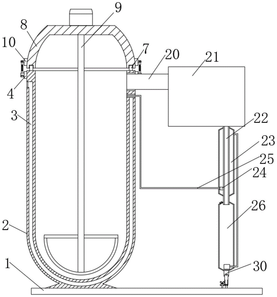
FIG. 1 is a schematic diagram of the overall structure of a waste heat recovery energy-saving heating system of a power plant according to the present invention;
FIG. 2 is a schematic diagram of the internal structure of the condenser pipe and the water storage pipe of the waste heat recovery energy-saving heating system of the power plant provided by the invention;
FIG. 3 is a schematic structural diagram of a water storage pipe of the waste heat recovery energy-saving heating system of the power plant provided by the invention;
FIG. 4 is a schematic diagram of the internal structure of the pressing plate and the fixing plate of the waste heat recovery energy-saving heating system of the power plant provided by the invention;
FIG. 5 is a schematic view of the overall structure of a pressing plate and a fixing plate of the waste heat recovery energy-saving heating system of the power plant provided by the invention;
FIG. 6 is a schematic structural diagram of a vertical plate and a cross knocking plate of the waste heat recovery energy-saving heating system of the power plant.
In the figure: 1. a base plate; 2. a boiler; 3. a heat preservation cavity; 4. a first bump; 5. a clamping block; 6. a first clamping groove; 7. a ring-shaped plate; 8. a furnace cover; 9. a stirring rod; 10. a second bump; 11. a transverse support; 12. a horizontal axis; 13. pressing a plate; 14. an extension plate; 15. a vertical slot; 16. a fixing plate; 17. a second clamping groove; 18. a slot; 19. a baffle plate; 20. a steam pipe; 21. a steam turbine generator; 22. an air duct; 23. a condenser tube; 24. a first water pump; 25. a water inlet pipe; 26. a water storage pipe; 27. an air valve; 28. a second water pump; 29. a water outlet pipe; 30. a connecting plate; 31. a vertical plate; 32. a rubber plate; 33. a vertical support; 34. a support plate; 35. a cross-shaped knocking plate; 36. a motor.
Detailed Description
The technical solutions in the embodiments of the present invention will be clearly and completely described below with reference to the drawings in the embodiments of the present invention, and it is obvious that the described embodiments are only a part of the embodiments of the present invention, and not all of the embodiments.
In the description of the present invention, it is to be understood that the terms "upper", "lower", "front", "rear", "left", "right", "top", "bottom", "inner", "outer", and the like, indicate orientations or positional relationships based on the orientations or positional relationships shown in the drawings, are merely for convenience in describing the present invention and simplifying the description, and do not indicate or imply that the device or element being referred to must have a particular orientation, be constructed and operated in a particular orientation, and thus, should not be construed as limiting the present invention.
Referring to fig. 1-6, a power plant waste heat recovery energy-saving heating system comprises a base plate 1, wherein a boiler 2 is arranged at the upper end of the base plate 1 close to the left side, a heat preservation cavity 3 is formed in the side wall of the boiler 2, a foamed ceramic heat preservation plate is filled in the heat preservation cavity 3, a first projection 4 is symmetrically arranged at the position of the outer side wall of the boiler 2 close to the top, a first clamping block 5 is arranged at one side of the first projection 4 away from the boiler 2, a first clamping groove 6 is formed at the bottom end of the first clamping block 5, a fixing plate 16 is sleeved on the clamping block 5 through the first clamping groove 6, a second clamping groove 17 is formed at the position of the front end of the fixing plate 16 close to the bottom in a penetrating manner, a slot 18 is formed at the upper end of the fixing plate 16, a baffle 19 is arranged at the position of the inner side wall of the, the bottom end of the furnace cover 8 is provided with a stirring rod 9, the upper end of the furnace cover 8 is provided with a motor, the output end of the motor penetrates through the furnace cover 8 and is fixedly connected with the upper end of the stirring rod 9, and the bottom of the stirring rod 9 is movably arranged at the bottom of the boiler 2 through the furnace cover 8.
The outer side wall of the furnace cover 8 is symmetrically provided with a second bump 10 near the bottom, one side of the second bump 10 far away from the furnace cover 8 is provided with a transverse support 11, a transverse shaft 12 is arranged between the two groups of transverse supports 11, a pressing plate 13 is sleeved on the transverse shaft 12, the bottom end of the pressing plate 13 is provided with an extension plate 14, the side wall of the extension plate 14 is provided with a vertical groove 15 near the middle position, the extension plate 14 is movably arranged in a slot 18 through the vertical groove 15 and a baffle 19, a fixed plate 16 is movably arranged with the pressing plate 13 through the extension plate 14 and the slot 18, the surface of the extension plate 14 is wound with a spring, one end of the spring is fixedly connected with the pressing plate 13, the other end of the spring is fixedly connected with the fixed plate 16, the fixed plate 16 is sleeved on the fixture block 5 through a first clamp groove 6 and a second clamp groove 17, the furnace cover 8, and the fixed plate 16 is pulled to enable the second clamping groove 17 to be located on one side of the clamping block 5, then the second clamping groove 17 is sleeved on the surface of the clamping block 5, then the pressing plate 13 and the fixed plate 16 are enabled to be close to each other due to the tensile force of the spring, the extending plate 14 is movably arranged in the slot 18 through the vertical groove 15 and the baffle plate 19 in a matched mode, the second clamping groove 17 is gradually clamped on the first clamping groove 6 under the matched mode of the fixed plate 16 and the spring, the position of the fixed plate 16 can be further locked, the first lug 4 and the second lug 10 are enabled to be close to each other, the furnace cover 8 is enabled to be well arranged at the upper end of the boiler 2, and the phenomenon that the.
A steam pipe 20 is arranged on the side wall of the boiler 2 close to the second bump 10, a turbo generator 21 is arranged on the side of the steam pipe 20 far away from the boiler 2, an air guide pipe 22 is arranged on one side of the turbo generator 21, a condensing pipe 23 is sleeved on the surface of the air guide pipe 22, a first water pump 24 is arranged inside the condensing pipe 23 close to the top, a water inlet pipe 25 is connected to the side wall of the first water pump 24, the water inlet pipe 25 far away from the first water pump 24 and penetrates through the condensing pipe 23 to be arranged at the top of the boiler 2, a water storage pipe 26 is sleeved at the bottom of the air guide pipe 22, an air valve 27 is arranged at the top of the water storage pipe 26, a second water pump 28 is arranged at the bottom of the water storage pipe 26, a water outlet pipe 29 is arranged on the side wall of, since the condenser 23 is filled with cooling water with a low temperature, when the steam moves in the air duct 22, the cooling water absorbs heat in the steam to lower the temperature of the steam, moisture in the steam is condensed into water drops and attached to the air duct 22, and then the accumulated water drops flow into the water storage tube 26 under the action of gravity.
The bottom end of the water storage pipe 26 is provided with a connecting plate 30, a vertical plate 31 is arranged between two groups of connecting plates 30 near the top, rubber plates 32 are symmetrically arranged on the side wall of the vertical plate 31 near the top, a vertical support 33 is movably arranged at the bottom of the vertical plate 31, rotating shafts are arranged at both ends of the side wall of the vertical plate 31, the vertical plate 31 is movably arranged between the connecting plate 30 and the vertical support 33 through the rotating shafts, a support plate 34 is arranged at the upper end of the bottom plate 1 near the vertical support 33, a cross-shaped knocking plate 35 is arranged between the two groups of support plates 34, a motor 36 is arranged at one side of the support plate 34, one end of the cross-shaped knocking plate 35 is contacted with the rubber plates 32, the motor 36 arranged at one side of the support plate 34 is started to rotate the cross-shaped knocking plate 35, the, thereby making the water drops attached to the inner side wall flow downwards and facilitating the collection of the condensed water drops.
The working principle and the using process of the invention are as follows: firstly, a worker welds a boiler 2 on the upper end of a bottom plate 1, then the other end of a steam pipe 20 is connected with a turbo generator 21, the turbo generator 21 is connected with an air guide pipe 22, a condensation pipe 23 is sleeved on the surface of the turbo generator, cooling water is filled in the condensation pipe 23, the other end of a water inlet pipe 25 is connected with the top of the boiler 2, a water storage pipe 26 is sleeved at the bottom of the air guide pipe 22, the other end of a water outlet pipe 29 is connected with the top of the condensation pipe 23, a first water pump 24 and a second water pump 28 are closed, a foamed ceramic insulation board is filled in an insulation cavity 3, the insulation effect of the boiler 2 can be effectively improved, water is filled in the boiler 2, a furnace cover 8 is sleeved on the upper end of the boiler 2 through an annular groove matching annular plate 7 to avoid the position deviation of the furnace cover 8 during installation, then a transverse shaft 12, then the second clamping groove 17 is sleeved on the surface of the clamping block 5, then the pressing plate 13 and the fixing plate 16 are close to each other due to the tensile force of the spring, the extension plate 14 is movably arranged inside the slot 18 through the vertical groove 15 in a matching manner with the baffle plate 19, the second clamping groove 17 is gradually clamped on the first clamping groove 6 under the matching of the fixing plate 16 and the spring, and then the position of the fixing plate 16 can be locked, so that the first projection 4 and the second projection 10 are close to each other, the furnace cover 8 is well arranged at the upper end of the boiler 2, the falling of the boiler 2 due to the increase of the air pressure inside the boiler 2 in use is avoided, the boiler 2 is used for heating water, the motor is started to rotate the stirring rod 9, the stirring rod 9 can stir the water to enable the water to be heated more rapidly, the time for generating steam is shortened, then the steam moves to the interior of the steam turbine generator 21 through the, because the condenser 23 is filled with cooling water with lower temperature, when the steam moves in the air duct 22, the cooling water absorbs heat in the steam to reduce the temperature of the steam, moisture in the steam can be condensed into water drops attached to the air duct 22, the accumulated water drops flow to the inside of the water storage tube 26 under the action of gravity, the motor 36 arranged on one side of the supporting plate 34 is started to rotate the cross-shaped knocking plate 35, the cross-shaped knocking plate 35 can knock the rubber plate 32, the vertical plate 31 vibrates between the connecting plate 30 and the vertical support 33, so that the water storage tube 26 and the air duct 22 vibrate, the water drops attached to the inner side wall of the water storage tube flow downwards, the condensed water drops can be collected more conveniently, the air valve 27 is opened to discharge waste gas in the steam from the inside of the water storage tube 26, the water pump 24 is started, and the cooling water heated by the steam in the condenser 23 flows into the boiler 2 through the water inlet tube 25, the second water pump 28 is started to move the water collected in the water storage pipe 26 to the interior of the condensation pipe 23, so that the waste heat in the steam can be well recycled, and the water can be recycled, so that energy is saved.
The above description is only for the preferred embodiment of the present invention, but the scope of the present invention is not limited thereto, and any person skilled in the art should be considered to be within the technical scope of the present invention, and the technical solutions and the inventive concepts thereof according to the present invention should be equivalent or changed within the scope of the present invention.