CN112842166B - Wet vacuum cleaning system - Google Patents
Wet vacuum cleaning system Download PDFInfo
- Publication number
- CN112842166B CN112842166B CN201911187308.0A CN201911187308A CN112842166B CN 112842166 B CN112842166 B CN 112842166B CN 201911187308 A CN201911187308 A CN 201911187308A CN 112842166 B CN112842166 B CN 112842166B
- Authority
- CN
- China
- Prior art keywords
- sewage tank
- surface cleaning
- cleaning system
- wet vacuum
- nursing seat
- Prior art date
- Legal status (The legal status is an assumption and is not a legal conclusion. Google has not performed a legal analysis and makes no representation as to the accuracy of the status listed.)
- Active
Links
Images


Classifications
-
- A—HUMAN NECESSITIES
- A47—FURNITURE; DOMESTIC ARTICLES OR APPLIANCES; COFFEE MILLS; SPICE MILLS; SUCTION CLEANERS IN GENERAL
- A47L—DOMESTIC WASHING OR CLEANING; SUCTION CLEANERS IN GENERAL
- A47L11/00—Machines for cleaning floors, carpets, furniture, walls, or wall coverings
- A47L11/29—Floor-scrubbing machines characterised by means for taking-up dirty liquid
- A47L11/30—Floor-scrubbing machines characterised by means for taking-up dirty liquid by suction
-
- A—HUMAN NECESSITIES
- A47—FURNITURE; DOMESTIC ARTICLES OR APPLIANCES; COFFEE MILLS; SPICE MILLS; SUCTION CLEANERS IN GENERAL
- A47L—DOMESTIC WASHING OR CLEANING; SUCTION CLEANERS IN GENERAL
- A47L11/00—Machines for cleaning floors, carpets, furniture, walls, or wall coverings
- A47L11/40—Parts or details of machines not provided for in groups A47L11/02 - A47L11/38, or not restricted to one of these groups, e.g. handles, arrangements of switches, skirts, buffers, levers
- A47L11/4002—Installations of electric equipment
- A47L11/4005—Arrangements of batteries or cells; Electric power supply arrangements
-
- A—HUMAN NECESSITIES
- A47—FURNITURE; DOMESTIC ARTICLES OR APPLIANCES; COFFEE MILLS; SPICE MILLS; SUCTION CLEANERS IN GENERAL
- A47L—DOMESTIC WASHING OR CLEANING; SUCTION CLEANERS IN GENERAL
- A47L11/00—Machines for cleaning floors, carpets, furniture, walls, or wall coverings
- A47L11/40—Parts or details of machines not provided for in groups A47L11/02 - A47L11/38, or not restricted to one of these groups, e.g. handles, arrangements of switches, skirts, buffers, levers
- A47L11/4013—Contaminants collecting devices, i.e. hoppers, tanks or the like
- A47L11/4016—Contaminants collecting devices, i.e. hoppers, tanks or the like specially adapted for collecting fluids
-
- A—HUMAN NECESSITIES
- A47—FURNITURE; DOMESTIC ARTICLES OR APPLIANCES; COFFEE MILLS; SPICE MILLS; SUCTION CLEANERS IN GENERAL
- A47L—DOMESTIC WASHING OR CLEANING; SUCTION CLEANERS IN GENERAL
- A47L11/00—Machines for cleaning floors, carpets, furniture, walls, or wall coverings
- A47L11/40—Parts or details of machines not provided for in groups A47L11/02 - A47L11/38, or not restricted to one of these groups, e.g. handles, arrangements of switches, skirts, buffers, levers
- A47L11/4094—Accessories to be used in combination with conventional vacuum-cleaning devices
Landscapes
- Accommodation For Nursing Or Treatment Tables (AREA)
- Devices For Medical Bathing And Washing (AREA)
Abstract
The invention discloses a wet vacuum cleaning system, comprising: the surface cleaning device comprises a shell, a vacuum motor, a cleaning head and a sewage tank which is detachably arranged on the shell, wherein the cleaning head, the sewage tank and the vacuum motor are in airflow communication through a suction channel; the nursing seat can be used for the surface cleaning equipment to stop in a non-working state; the surface cleaning apparatus also has a sump release mechanism configured to disengage the sump from the surface cleaning apparatus when the surface cleaning apparatus is resting on the nursing seat. The invention can eject the sewage tank after the equipment is used, effectively remind a user of cleaning the sewage tank, prevent the sewage tank from smelling and generating peculiar smell, and improve the use feeling of the equipment.
Description
Technical Field
The invention relates to the field of household cleaning equipment, in particular to wet type surface cleaning equipment.
Background
In the prior art, surface cleaning devices are divided into wet type cleaning devices and dry type cleaning devices, the dry type cleaning devices only clean the surfaces such as the ground and the wall surface by means of vacuum suction force provided by a vacuum motor, and the wet type cleaning devices need to clean by means of cleaning agent or clean water, and transfer sewage, debris and the like on the surface to be cleaned into a sewage tank by means of friction between a rolling brush rotating at a high speed and the ground. After the consumer used the equipment, often can forget to empty the sewage case, sewage is left the sewage case for a long time and is easy to breed the bacterium, produce the peculiar smell, and the foul solution is deposited and is adhered to in the sewage incasement wall easily after a long time in addition, is difficult to clear up, and current wet-type surface cleaning equipment is bright few and reminds the user to empty sewage case and clean the round brush.
Disclosure of Invention
In order to solve the above technical problems, an object of the present invention is to provide a surface cleaning apparatus capable of effectively reminding a user of dumping a sump.
In order to achieve the above object, the first technical solution adopted by the present invention is:
a wet vacuum cleaning system, comprising:
the surface cleaning device comprises a shell, a vacuum motor, a cleaning head and a sewage tank which is detachably arranged on the shell, wherein the cleaning head, the sewage tank and the vacuum motor are in airflow communication through a suction channel;
the nursing seat can be used for the surface cleaning equipment to stop in a non-working state;
the surface cleaning apparatus also has a sump release mechanism configured to disengage the sump from the surface cleaning apparatus when the surface cleaning apparatus is resting on the nursing seat.
In a further preferred embodiment of the present invention, the housing has an accommodating chamber for accommodating the waste water tank, the release mechanism has a holding state and a release state, and the waste water tank is fixedly connected to the accommodating chamber in the holding state; in the release state, the sewage tank is not connected with the containing cavity, and at least part of the sewage tank is positioned outside the containing cavity.
In a further preferred embodiment of the present invention, the release mechanism includes a locking member for locking the waste water tank and the housing relative to each other, and an ejecting member for ejecting at least a part of the waste water tank from the receiving chamber.
Preferably, the surface cleaning apparatus further comprises a charging plug and a control board electrically connected to the release mechanism, respectively, the nursing seat has a charging terminal matching with the charging plug, and the control board is configured to convert the release mechanism into a release state when the charging terminal is conducted to the charging plug.
In a further preferred embodiment of the above technical solution, the surface cleaning device and/or the nursing seat is provided with a sensor, the locking member comprises an electric locking hook in signal connection with the sensor, and the ejecting member comprises an electric spring in signal connection with the sensor.
Preferably, the surface cleaning apparatus further comprises a linkage mechanism respectively linked with the locking member and the ejecting member, the nursing seat is provided with a trigger member matched with the linkage mechanism, and the trigger member is configured to apply an acting force to the linkage mechanism when the surface cleaning apparatus is parked on the nursing seat.
According to a further preferred embodiment of the above technical solution, the storage cavity is located in the middle of the housing, a front opening of the storage cavity forms a space for taking and placing the sewage tank, and the ejection member is disposed on a rear wall or a bottom wall of the storage cavity.
In a further preferred aspect of the above technical solution, the front portion of the receiving cavity has a protection edge extending upward from the receiving cavity, and the protection edge is slightly larger than the outer diameter of the sewage tank.
According to a further preferred embodiment of the above technical scheme, the sewage tank comprises a cylinder body and a cover body covering the cylinder body in a sealing manner.
In a further preferred embodiment of the above solution, the wet vacuum cleaning system further comprises a reminder module configured to emit an audio or light or electrical signal when the surface cleaning apparatus is parked on the nursing seat.
The invention can eject the sewage tank after the equipment is used, effectively remind a user of cleaning the sewage tank, prevent the sewage tank from smelling and generating peculiar smell, and improve the use feeling of the equipment.
Drawings
FIG. 1 is a schematic diagram of a wet vacuum cleaning system according to one embodiment of the present invention;
FIG. 2 is a schematic diagram of a wet vacuum cleaning system according to a second embodiment of the present invention;
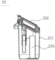
FIG. 3 is a schematic view showing the construction of a waste water tank according to the present invention;
wherein: 100. a nursing seat; 11. a trigger;
200. a surface cleaning device; 20. a housing; 202. a protective edge; 21. a cleaning head; 22. a suction channel; 23. a sewage tank; 231. a barrel; 232. a cover body; 233. a water inlet pipe; 24. a locking member; 25. a pop-up member; 26. a receiving cavity; 300. a handle portion.
Detailed Description
The technical contents, the structural features, the achieved objects and the effects of the invention are explained in detail in the following with reference to the embodiments.
The following disclosure provides many different embodiments, or examples, for implementing different features of the invention. To simplify the disclosure of the present invention, the components and arrangements of specific examples are described below. Of course, they are merely examples and are not intended to limit the present invention. Furthermore, the present invention may repeat reference numerals and/or letters in the various examples. This repetition is for the purpose of simplicity and clarity and does not in itself dictate a relationship between the various embodiments and/or configurations discussed. Additionally, the present invention provides examples of various specific processes and materials, but one of ordinary skill in the art may recognize the applicability of other processes and/or the use of other materials.
The front-to-back, left-to-right, and up-down directions described in this specification correspond to the front-to-back, left-to-right, and up-to-down directions of a consumer during normal operation of the cleaning apparatus, as indicated by arrows in fig. 1.
The invention is described below with reference to figures 1-3. The wet vacuum cleaning system shown in fig. 1 includes: a nursing seat 100 and a surface cleaning apparatus 200 that can be mounted on the nursing seat 100 in an upright position. The surface cleaning device can be parked on the nursing seat when the surface cleaning device is in a non-working state, the rear part of the surface cleaning device 200 is provided with a charging plug matched with a charging terminal, the nursing seat 100 is provided with the charging terminal for charging the surface cleaning device 200, and the nursing seat 100 is also provided with a cleaning groove for cleaning the rolling brush part of the surface cleaning device.
The surface cleaning device comprises a cleaning main machine, a handle part 300 which is fixedly or detachably connected with the cleaning main machine and is suitable for being held by hands, and a cleaning head 21 arranged at the bottom of the cleaning main machine. In floor cleaning, a user pushing on the handle portion 300 operates the surface cleaning apparatus to move the surface cleaning apparatus back and forth and side to side. The cleaning main machine comprises a vacuum motor, a control device for receiving user instructions and controlling the action of each electric component, and the like (not shown in the figure). The cleaning host can be a vertical vacuum cleaner host, a floor cleaning machine host, or a vacuum cleaner host in the form of a handheld vacuum cleaner host and the like. For upright floor washers there is usually a clean water tank for clean cleaning liquid and a waste tank 23 for waste water in the main body of the machine, whereas for hand-held vacuum cleaner main units there is usually a removable attachment for the waste tank and clean water tank. That is, the concepts of the present invention may be adapted for use with a variety of vacuum surface cleaning apparatuses and are not limited to use with a particular model.
In this embodiment, the surface cleaning apparatus includes a housing 20, the clean water tank and the sewage tank 23 are both disposed on the housing 20, a storage cavity 26 capable of accommodating the sewage tank 23 is formed in the middle of the housing 20, the front side of the storage cavity 26 in this embodiment is open to form a slot for taking and placing the sewage tank, the top wall, the rear wall and the bottom wall of the storage cavity are respectively defined by a part of housing, the front side of the storage cavity further has a short protection edge, and the external view of the protection edge is slightly larger than the external diameter of the sewage tank, so as to prevent the sewage tank from accidentally falling from the storage cavity. The housing 20 also forms a suction channel for air flow communication between the cleaning head, the waste tank 23 and the vacuum motor.
The cleaning head 21 is provided with a suction port, a rolling brush rotatably connected to the suction port, a scraping strip and the like. When the cleaning head 21 moves on the ground, the bristles of the rolling brush rub against the ground, the fiber fluff is fully distributed on the surface of the rolling brush, the ground can be scrubbed, meanwhile, sewage on the ground is rolled up, and the sewage enters the sewage tank through the suction channel 11 under the action of vacuum suction.
In order to remind consumers to pour and clean the sewage tank in time after the use of the surface cleaning equipment, the surface cleaning equipment provided by the invention is also provided with a sewage tank releasing mechanism and a reminding module. The release mechanism is used for locking the sewage tank 23 when the equipment is in a working state and automatically ejecting the sewage tank after cleaning is finished, and has a holding state and a releasing state, wherein in the holding state, the sewage tank 23 is accommodated in the accommodating cavity 26 and is locked with the shell 20; in the release state, the space between the sewage tank 23 and the housing 20 is unlocked, and at least a part of the sewage tank 23 is ejected out of the accommodating cavity 26. The reminding module sends out acousto-optic and electric reminding information when the surface cleaning equipment stops at the nursing seat or in a delayed mode, and reminds consumers of cleaning the sewage tank.
The release mechanism can be controlled to act in at least three ways:
the surface cleaning device is controlled by a control panel setting program arranged in the surface cleaning device, the releasing mechanism is composed of an electric element and receives a control signal action of the control panel, when the surface cleaning device is parked at a nursing seat, the surface cleaning device is in a non-working state, at the moment, a charging plug of the surface cleaning device is electrically conducted with a charging terminal of the nursing seat, the control panel immediately sends a signal to enable the releasing mechanism to pop out of the sewage tank, the reminding module sends out acousto-optic electric information, and when a consumer finishes cleaning the sewage tank and installs the sewage tank again, the releasing mechanism enters a holding state.
Secondly, the motion of the release mechanism is controlled in an electronic induction mode, as shown in fig. 1, a sensor such as a photoelectric sensor, a hall sensor or a gravity sensor is arranged on the nursing seat 100, the locking member 24 is an electromagnetic locking hook, the ejecting member 25 is an electromagnetic spring, the electromagnetic locking hook and the electromagnetic spring are in signal connection with the sensor, and when the sensor detects that the surface cleaning device 200 is placed on the nursing seat 100, the sensor sends a motion signal to successively release the electromagnetic locking hook and the electromagnetic spring to push out the sewage tank.
Thirdly, the release mechanism is controlled to act in a mechanical sensing mode, as shown in fig. 2, a raised trigger piece 11 is arranged on the nursing seat 100, a linkage mechanism 27 linked with the ejecting piece and the locking piece is arranged at the rear part of the surface cleaning equipment 200, when the surface cleaning equipment 200 is placed on the nursing seat for charging, the trigger piece 11 just can give an acting force to the linkage mechanism 27, so that the linkage mechanism 27 unlocks the ejecting piece and the locking piece, and when a user takes off the sewage tank for cleaning and installs the sewage tank on the shell again, the ejecting piece and the locking piece just reset. The resetting of the linkage mechanism can be designed according to specific requirements, for example, the linkage mechanism can be designed to reset after a sewage tank is installed, the trigger piece 11 stores force, and the trigger piece 11 resets after the surface cleaning equipment is removed from the nursing seat; alternatively, the linkage may be designed to store power after installation of the waste tank and reset after the surface cleaning apparatus is removed from the nursing seat. The trigger 11 can be a convex rod or an electromagnet, and the linkage mechanism 27 can be realized by selecting a linkage rod or a magnetic material and the like.
Referring to fig. 3, in order to prevent the sewage from being accidentally spilled when the sewage tank 23 is ejected, the sewage tank 23 includes a cylinder 231 and a cover 231 covering the cylinder 231, and a water inlet pipe 233 for the sewage to enter is disposed in the middle of the cylinder 231.
In other embodiments of the present invention, the waste water tank may be disposed externally to the housing, such as on the top of the housing, and when the release mechanism releases the waste water tank, the waste water tank is still on the top of the housing, but there is no fixed connection between the housings.
The above embodiments are merely illustrative of the technical ideas and features of the present invention, and the purpose thereof is to enable those skilled in the art to understand the contents of the present invention and implement the present invention, and not to limit the protection scope of the present invention. All equivalent changes or modifications made according to the spirit of the present invention should be covered within the protection scope of the present invention.
Claims (10)
1. A wet vacuum cleaning system, comprising:
the surface cleaning device comprises a shell, a vacuum motor, a cleaning head and a sewage tank which is detachably arranged on the shell, wherein the cleaning head, the sewage tank and the vacuum motor are in airflow communication through a suction channel;
the nursing seat can be used for the surface cleaning equipment to stop in a non-working state;
the method is characterized in that:
the surface cleaning apparatus also has a sump release mechanism configured to disengage the sump from the surface cleaning apparatus when the surface cleaning apparatus is resting on the nursing seat.
2. The wet vacuum cleaning system of claim 1, wherein: the shell is provided with an accommodating cavity for accommodating the sewage tank, the release mechanism has a holding state and a release state, and the sewage tank is fixedly connected in the accommodating cavity in the holding state; in the release state, the sewage tank is not connected with the containing cavity, and at least part of the sewage tank is positioned outside the containing cavity.
3. The wet vacuum cleaning system of claim 2, wherein: the release mechanism comprises a locking piece which can enable the sewage tank and the shell to be locked relatively and an ejection piece which can push the sewage tank out of the containing cavity at least partially.
4. The wet vacuum cleaning system of claim 3, wherein: the surface cleaning device is provided with a charging plug and a control board which is respectively electrically connected with the releasing mechanism, the nursing seat is provided with a charging terminal which is matched with the charging plug, and the control board is configured to convert the releasing mechanism into a releasing state when the charging terminal is conducted with the charging plug.
5. The wet vacuum cleaning system of claim 3, wherein: the surface cleaning equipment and/or the nursing seat are/is provided with a sensor, the locking piece comprises an electric locking hook in signal connection with the sensor, and the ejecting piece comprises an electric spring in signal connection with the sensor.
6. The wet vacuum cleaning system of claim 3, wherein: the surface cleaning device is provided with a linkage mechanism which is respectively linked with the locking piece and the ejecting piece, the nursing seat is provided with a trigger piece which is matched with the linkage mechanism, and the trigger piece is configured to apply an acting force to the linkage mechanism when the surface cleaning device is stopped on the nursing seat.
7. The wet vacuum cleaning system of claim 3, wherein: the containing cavity is positioned in the middle of the shell, a front opening of the containing cavity forms a space for taking and placing the sewage tank, and the ejecting piece is arranged on the rear wall or the bottom wall of the containing cavity.
8. The wet vacuum cleaning system of claim 7, wherein: the front part of the containing cavity is provided with a protective edge extending upwards from the containing cavity, and the protective edge is slightly larger than the outer diameter of the sewage tank.
9. The wet vacuum cleaning system of claim 1, wherein: the sewage tank comprises a cylinder body and a cover body which is covered on the cylinder body in a sealing way.
10. The wet vacuum cleaning system of claim 1, wherein: the surface cleaning device also comprises a reminding module which is configured to emit audio frequency or light or electric signals when the surface cleaning device is parked on the nursing seat.
Priority Applications (1)
| Application Number | Priority Date | Filing Date | Title |
|---|---|---|---|
| CN201911187308.0A CN112842166B (en) | 2019-11-28 | 2019-11-28 | Wet vacuum cleaning system |
Applications Claiming Priority (1)
| Application Number | Priority Date | Filing Date | Title |
|---|---|---|---|
| CN201911187308.0A CN112842166B (en) | 2019-11-28 | 2019-11-28 | Wet vacuum cleaning system |
Publications (2)
| Publication Number | Publication Date |
|---|---|
| CN112842166A CN112842166A (en) | 2021-05-28 |
| CN112842166B true CN112842166B (en) | 2022-02-11 |
Family
ID=75985888
Family Applications (1)
| Application Number | Title | Priority Date | Filing Date |
|---|---|---|---|
| CN201911187308.0A Active CN112842166B (en) | 2019-11-28 | 2019-11-28 | Wet vacuum cleaning system |
Country Status (1)
| Country | Link |
|---|---|
| CN (1) | CN112842166B (en) |
Families Citing this family (2)
| Publication number | Priority date | Publication date | Assignee | Title |
|---|---|---|---|---|
| CN113303731B (en) * | 2021-06-01 | 2022-06-21 | 北京顺造科技有限公司 | Separation structure, sewage storage device and surface cleaning equipment |
| CN113876242B (en) * | 2021-09-30 | 2023-02-03 | 添可智能科技有限公司 | Cleaning device |
Citations (6)
| Publication number | Priority date | Publication date | Assignee | Title |
|---|---|---|---|---|
| JPH09479A (en) * | 1995-06-20 | 1997-01-07 | Fujitsu General Ltd | Floor surface cleaning machine |
| CN204909322U (en) * | 2015-07-03 | 2015-12-30 | 苏州德莱电器有限公司 | Cleaning device |
| CN109199220A (en) * | 2018-09-30 | 2019-01-15 | 江苏美的清洁电器股份有限公司 | Wet-dry dust catcher |
| CN208510945U (en) * | 2017-10-31 | 2019-02-19 | 苏州德莱电器有限公司 | A kind of floor surface washing machine |
| CN109805832A (en) * | 2019-03-27 | 2019-05-28 | 苏州诚河清洁设备有限公司 | Soiling solution recycles component and surface cleaning apparatus |
| JP2019115789A (en) * | 2019-04-24 | 2019-07-18 | 深▲セン▼市赫▲ジ▼科技有限公司HIZERO Technologies Co.,Ltd. | Floor cleaner |
-
2019
- 2019-11-28 CN CN201911187308.0A patent/CN112842166B/en active Active
Patent Citations (6)
| Publication number | Priority date | Publication date | Assignee | Title |
|---|---|---|---|---|
| JPH09479A (en) * | 1995-06-20 | 1997-01-07 | Fujitsu General Ltd | Floor surface cleaning machine |
| CN204909322U (en) * | 2015-07-03 | 2015-12-30 | 苏州德莱电器有限公司 | Cleaning device |
| CN208510945U (en) * | 2017-10-31 | 2019-02-19 | 苏州德莱电器有限公司 | A kind of floor surface washing machine |
| CN109199220A (en) * | 2018-09-30 | 2019-01-15 | 江苏美的清洁电器股份有限公司 | Wet-dry dust catcher |
| CN109805832A (en) * | 2019-03-27 | 2019-05-28 | 苏州诚河清洁设备有限公司 | Soiling solution recycles component and surface cleaning apparatus |
| JP2019115789A (en) * | 2019-04-24 | 2019-07-18 | 深▲セン▼市赫▲ジ▼科技有限公司HIZERO Technologies Co.,Ltd. | Floor cleaner |
Also Published As
| Publication number | Publication date |
|---|---|
| CN112842166A (en) | 2021-05-28 |
Similar Documents
| Publication | Publication Date | Title |
|---|---|---|
| EP3785594B1 (en) | Surface cleaning apparatus | |
| CN112842166B (en) | Wet vacuum cleaning system | |
| US20220015597A1 (en) | Surface cleaning apparatus and tray | |
| CN112656320A (en) | Self-cleaning method for surface cleaning device and wet surface cleaning system | |
| CN109805832B (en) | Dirty liquid recovery subassembly and surface cleaning equipment | |
| CN109363571A (en) | Clean robot and its component that mops floor | |
| JP2005211426A (en) | Self-traveling cleaner | |
| AU2015315010A1 (en) | Trashcan system and related methods of use | |
| CN106628753A (en) | Multifunctional intelligent garbage can | |
| JP2021511956A (en) | High-pressure washing machine | |
| CN212394810U (en) | Maintenance device and cleaning system | |
| CN212394808U (en) | Maintenance device and cleaning system | |
| CN113827143A (en) | Method for treating an active surface cleaning device and wet surface cleaning system | |
| CN113925407B (en) | Integration station of wet surface cleaning system and surface cleaning system | |
| CN205617520U (en) | Remote controller can embed and automatic intelligent closestool who charges | |
| US20220175212A1 (en) | Dosing of a solid detergent in a domestic dishwashing machine | |
| CN216652195U (en) | Cleaning device | |
| KR101010422B1 (en) | A cleaning apparatus of a automatic vacuum cleaner and cleaning method thereof | |
| CN212394809U (en) | Maintenance device and cleaning system | |
| JP2001286428A (en) | Dish washer | |
| CN210931268U (en) | Distributor of dish washer | |
| CN106809181A (en) | A kind of automobile intelligent cleaner control system | |
| CN217310123U (en) | Integrated station of wet surface cleaning system and surface cleaning system | |
| CN113303706A (en) | Maintenance prompting method for maintenance equipment, cleaning system and storage medium | |
| CN216652196U (en) | Wet surface cleaning system and interface pedestal |
Legal Events
| Date | Code | Title | Description |
|---|---|---|---|
| PB01 | Publication | ||
| PB01 | Publication | ||
| SE01 | Entry into force of request for substantive examination | ||
| SE01 | Entry into force of request for substantive examination | ||
| GR01 | Patent grant | ||
| GR01 | Patent grant |