CN112832579A - Suspension derrick type inverted lifting system and application method thereof - Google Patents
Suspension derrick type inverted lifting system and application method thereof Download PDFInfo
- Publication number
- CN112832579A CN112832579A CN202011598887.0A CN202011598887A CN112832579A CN 112832579 A CN112832579 A CN 112832579A CN 202011598887 A CN202011598887 A CN 202011598887A CN 112832579 A CN112832579 A CN 112832579A
- Authority
- CN
- China
- Prior art keywords
- derrick
- pole
- section
- frame
- lifting
- Prior art date
- Legal status (The legal status is an assumption and is not a legal conclusion. Google has not performed a legal analysis and makes no representation as to the accuracy of the status listed.)
- Pending
Links
- 238000000034 method Methods 0.000 title claims abstract description 16
- 239000000725 suspension Substances 0.000 title claims abstract description 14
- 238000009434 installation Methods 0.000 claims description 18
- 238000010276 construction Methods 0.000 claims description 11
- 230000002146 bilateral effect Effects 0.000 claims description 2
- XEEYBQQBJWHFJM-UHFFFAOYSA-N Iron Chemical compound [Fe] XEEYBQQBJWHFJM-UHFFFAOYSA-N 0.000 description 6
- 229910000831 Steel Inorganic materials 0.000 description 3
- 229910052742 iron Inorganic materials 0.000 description 3
- 239000000463 material Substances 0.000 description 3
- 239000010959 steel Substances 0.000 description 3
- 230000005540 biological transmission Effects 0.000 description 2
- 238000010586 diagram Methods 0.000 description 1
- 210000001503 joint Anatomy 0.000 description 1
Images


Classifications
-
- E—FIXED CONSTRUCTIONS
- E04—BUILDING
- E04H—BUILDINGS OR LIKE STRUCTURES FOR PARTICULAR PURPOSES; SWIMMING OR SPLASH BATHS OR POOLS; MASTS; FENCING; TENTS OR CANOPIES, IN GENERAL
- E04H12/00—Towers; Masts or poles; Chimney stacks; Water-towers; Methods of erecting such structures
- E04H12/34—Arrangements for erecting or lowering towers, masts, poles, chimney stacks, or the like
Abstract
The invention discloses a suspension holding rod derrick type inverted lifting system and an application method thereof, wherein the system comprises a base, a derrick, a lifting device and a limiting waist ring, the derrick is of a detachable assembly structure, the lower end of the derrick is detachably connected with the base, the lifting device comprises a power device and a lifting frame, the lifting frame and the base are arranged on the lower part of an inner cavity of the derrick in parallel, the holding rod is clamped by the lifting frame, the power device provides reciprocating power for the lifting frame to lift the holding rod, and the limiting waist ring is horizontally fixed on the top of the inner cavity of the derrick, so that the stability of the holding rod during lifting is ensured. The lifting frame is designed into a derrick with a compact structure, the inner cavity of the lifting frame only needs to be slightly larger than the plane size of the holding rod, the lifting frame can be manufactured in a modular factory, the weight of a single piece of a module can be controlled within 100kg, the lifting frame is suitable for manual transportation in mountainous areas, the identification is convenient, and the field assembly is rapid. The hoisting frame can upwards promote repeatedly and embrace the pole segment section, and the suspension flip-chip of embracing the pole segment section is accomplished to the completion, only needs to embrace the pole segment section with the help of the derrick and pass through bolt and nut with upper and lower and connect fixed factor of safety height.
Description
Technical Field
The invention relates to the field of assembly construction of transmission line engineering iron towers, in particular to a suspension holding pole derrick type inverted lifting system and an application method thereof.
Background
At present, suspension holding pole assembling is adopted in the construction of the iron tower assembling of the power transmission line engineering, the method for assembling the tower is the most widely applied and the highest technical proficiency, and the holding pole assembling is in an inverted installation mode and a forward installation mode.
Due to large operation risk and large control difficulty, the holding pole formal installation is strictly prohibited to be adopted; in the foundation-based large 500kV and extra-high voltage engineering, the upside-down mounting needs to firstly utilize the whole assembling upper section of the holding pole of the small-sized inverted-falling herringbone holding pole, then utilize the upper section of the holding pole to assemble the iron tower to a certain height, then adopt the upside-down mounting lifting mode, and connect the rest sections of the holding pole at the lower part of the holding pole until the whole assembling is completed, and the mode leads constructors to be unwilling to adopt due to the complicated construction procedures. The construction personnel are caused to risk and adopt the normal mounting mode to carry out holding pole assembly, and the safety risk exists.
Disclosure of Invention
The invention aims to provide a suspension derrick type inverted lifting system with compact structure, rapid field assembly and high safety coefficient and an application method thereof.
The invention provides a suspension holding rod derrick type inverted lifting system which comprises a base, a derrick, a lifting device and a limiting waist ring, wherein the derrick is of a detachable assembly structure, the lower end of the derrick is detachably connected with the base, the lifting device comprises a power device and a lifting frame, the lifting frame and the base are arranged on the lower portion of an inner cavity of the derrick in parallel, the holding rod is clamped by the lifting frame, the power device provides power for the lifting frame to achieve holding rod lifting, and the limiting waist ring is horizontally fixed on the top of the inner cavity of the derrick.
In an embodiment of the above technical scheme, the base includes well seat and the limit seat of its bilateral symmetry connection, and the center section of well seat is pole section flange joint seat, the both sides of center section and is the pole section and enters into the seat, can dismantle the connection through the fastener between well seat and the limit seat, and the four corners symmetric connection of both sides seat has the landing leg of adjustable height.
In one embodiment of the above technical solution, the derrick comprises a plurality of unit frames assembled up and down, each unit frame comprises two main sheets facing in parallel and a connecting sheet detachably connected between the two main sheets, adjacent unit frames are detachably connected by a fastener, and the lower end of a first unit frame is symmetrically connected to the side base; the outer side of the upright post of one of the unit frame main sheets is hinged with a small holding rod component, and the small holding rod component comprises a rod body and a pulley fixed at the upper end of the rod body.
In one embodiment of the above technical solution, the main piece includes two upright posts and a connecting rod between the upright posts, flanges are provided at two ends of the upright posts, and ear plates for fixing the connecting piece are provided at the same side of the top and the bottom of the upright posts; the connecting piece comprises a horizontal rod and an inclined rod between the horizontal rods, the horizontal rod is arranged in parallel from top to bottom, lug plates corresponding to the lug plates on the stand column are arranged at two ends of the horizontal rod, and the corresponding lug plates are fixedly connected through bolts and nuts.
In one embodiment of the above technical solution, the lifting frame includes a square frame, a clamping assembly and a guide roller assembly; the clamping assembly comprises vertical clamping blocks and horizontal connecting plates, the cross section of each vertical clamping block is L-shaped, each horizontal connecting plate is an L-shaped plate, the two horizontal connecting plates are connected to the top and the bottom of the outer wall of each vertical clamping block in parallel, two sides and corners of each horizontal connecting plate are respectively provided with parallel waist circular holes, and two side edges of each vertical clamping block are respectively provided with a circular hole; the guide roller assembly comprises a yoke plate, a double-lug plate seat and a guide roller group hinged between the two lug plates, and the bottom surface of the double-lug plate seat is provided with a round hole corresponding to the waist round hole on the horizontal yoke plate; the inner corners of the inner cavity of the square frame are symmetrically connected with clamping components; the top surface and the bottom surface of the four corners of the square frame are respectively connected with a guide roller component extending out of the outer edge of the square frame; the outer sides of a pair of frameworks of the square framework are symmetrically connected with pulleys.
In one implementation mode of the technical scheme, horizontal brackets are symmetrically arranged at four corners of the lower part of an inner cavity of the derrick, and lifting guide rails are vertically connected to the horizontal brackets; the lifting frame is positioned above the horizontal bracket, and the guide wheel set clamps the lifting guide rail to slide.
In an embodiment of the above technical solution, the limiting waist ring includes a square frame, and a limiting pulley assembly, a pulley and a stay wire fixing tube connected thereto, the limiting pulley assembly includes a mounting frame and guide pulleys hinged to the top and the bottom thereof, a limiting groove is provided at a middle position of the guide pulleys, and positions and number of the pulleys correspond to those of the pulleys on the lifting frame.
In one embodiment of the above technical scheme, the power device is an oil cylinder, two groups of oil cylinders are vertically arranged on two sides of the derrick, the lower end of the cylinder body is hinged on the side seat, the corresponding side of the square frame is provided with a hinged seat, and the upper end of a piston rod of the oil cylinder is hinged and fixed with the hinged seat through a pin shaft to lift the lifting frame upwards; or the power device is a winching machine, the side seat is provided with a pulley which is upward corresponding to the lifting frame and the limiting waist ring, and the winching machine lifts the lifting frame upwards through the lifting rope and the pulley.
The invention provides a method for inversely installing a holding pole by utilizing the system, wherein a power device of a jacking device adopts an oil cylinder, and the method comprises the following steps:
(1) leveling the ground at the installation position, assembling the base and adjusting the levelness of the base through the supporting legs to meet the requirement;
(2) assembling a derrick, connecting and fixing the lower end of the derrick with a side seat of a base, and installing a lifting frame, a bracket, a guide rail and a limiting waist ring at the specified position of the derrick;
(3) stay wires are respectively fixed at the top of the derrick and four corners of the base to keep the derrick vertical and stable;
(4) installing an oil cylinder;
(5) fixing an external stay wire at the top of the first assembled holding pole standard section, pushing the external stay wire into the derrick, clamping four corners of the holding pole section by a lifting frame, and simultaneously adjusting the center of the holding pole section to coincide with the center of the derrick;
(6) the oil cylinder works, the holding rod standard section is lifted upwards until the next holding rod standard section can be pushed into the derrick, the holding rod standard section lifted in place is supported by the bracket, and an external stay wire ensures that the holding rod standard section is in a vertical state;
(7) pushing the second holding pole standard section into the derrick according to the step (5), assembling the upper end of the holding pole standard section and the lower end of the first holding pole standard section, and retracting the piston rod of the oil cylinder;
(8) repeating the step (6) until all the holding pole standard sections are lifted and assembled in sequence;
(9) and when the top of the pole holding standard section exceeds the height of the derrick, the pole holding conical section is lifted through the small pole holding, and finally the top cap of the pole holding conical section is lifted through the small pole holding.
(10) Fixing an outer bracing wire of the holding pole;
(11) when the holding pole is not lifted off the ground, the derrick, the lifting frame, the bracket, the guide rail and the limiting waist ring are dismantled, so that the installation and construction of a supporting system under the holding pole are facilitated.
The invention provides a method for inversely installing a holding pole by utilizing the system, wherein a power device of a jacking device adopts a grinder, and the method comprises the following steps:
(1) leveling the ground at the installation position, assembling the base and adjusting the levelness of the base through the supporting legs to meet the requirement;
(2) assembling a derrick, connecting and fixing the lower end of the derrick with a side seat of a base, and installing a lifting frame, a bracket, a guide rail and a limiting waist ring at the specified position of the derrick;
(3) stay wires are respectively fixed at the top of the derrick and four corners of the base to keep the derrick vertical and stable;
(4) a lifting rope is laid on the base, the lifting frame and the pulley on the limiting waist ring, and the lifting rope is connected with the winching;
(5) fixing an external stay wire at the top of the first assembled holding pole standard section, pushing the external stay wire into the derrick, clamping four corners of the holding pole section by a lifting frame, and simultaneously adjusting the center of the holding pole section to coincide with the center of the derrick;
(6) winching, namely lifting the pole standard section upwards until the next pole standard section can be pushed into the derrick, supporting the pole standard section lifted in place through a bracket, and ensuring that the pole standard section is in a vertical state through an external stay wire;
(7) pushing the second holding pole standard section into the derrick according to the step (5), assembling the upper end of the holding pole standard section and the lower end of the first holding pole standard section, performing winching and grinding in a reverse direction, and descending the lifting frame to return;
(8) repeating the step (6) until all the holding pole standard sections are lifted and assembled in sequence;
(9) and when the top of the pole holding standard section exceeds the height of the derrick, the pole holding conical section is lifted through the small pole holding, and finally the top cap of the pole holding conical section is lifted through the small pole holding.
(10) Fixing an outer bracing wire of the holding pole;
(11) when the holding pole is not lifted off the ground, the derrick, the lifting frame, the bracket, the guide rail and the limiting waist ring are dismantled, so that the installation and construction of a supporting system under the holding pole are facilitated.
The derrick is designed into a derrick with a compact structure, the plane size of the derrick is only slightly larger than that of the holding rod, the derrick is of a detachable assembly structure, the derrick can be manufactured in a modular factory, the weight of a single piece of an assembly module can be controlled within 100kg, the derrick is suitable for manual transportation in mountainous areas, identification is convenient, and field assembly is rapid. Set up the hoisting frame in the lower part of derrick inner chamber, grasp the four corners of embracing the pole section through the hoisting frame, exert reciprocating power for the hoisting frame, make it upwards promote repeatedly and embrace the pole section, hold the suspension flip-chip of pole section until accomplishing, the staff only need with the help of the derrick with upper and lower embrace the pole section and pass through bolt and nut connection fixed, do not have other high altitude operations, factor of safety is high.
Drawings
Fig. 1 is a schematic front view of a first embodiment of the present invention.
Fig. 2 is a left side view of fig. 1.
Fig. 3 is a schematic three-dimensional structure of fig. 1.
Fig. 4 is an enlarged schematic view of a portion a in fig. 3.
Fig. 5 is an enlarged schematic view of a portion B in fig. 3.
Fig. 6 is an enlarged schematic view of the portion C in fig. 3.
Fig. 7 is a schematic diagram of lift cord routing according to the second embodiment.
Detailed Description
First embodiment, as can be seen from fig. 1 to 6, the suspension derrick type inverted lifting system disclosed in this embodiment includes a base 1, a derrick 2, a lifting frame 3, an oil cylinder 4, a guide rail 5, a horizontal bracket 6, and a waist limiting ring 7.
The base 1 is a split type combined structure and comprises a middle base 11 and two side bases 12 which are symmetrically connected with each other, wherein the central section of the middle base is a rod section flange connecting base, the two sides of the central section are rod section entering bases, the middle base 11 and the side bases 12 are detachably connected through fasteners, and the four corners of the two side bases 12 are symmetrically connected with supporting legs 13 with adjustable heights. The installation levelness of the base can be adjusted through the supporting legs.
The derrick 2 comprises a plurality of unit frames, each unit frame comprises two main sheets 21 which are opposite in parallel and a connecting sheet 22 which is detachably connected between the two main sheets, and adjacent unit frames are detachably connected through fasteners.
The main piece 21 comprises two upright posts 211 and a connecting rod 212 between the upright posts, wherein flanges are arranged at two ends of each upright post, and ear plates for fixing the connecting pieces are arranged at the same side of the top and the bottom of each upright post.
The connecting piece 22 comprises a horizontal rod and an inclined rod arranged between the horizontal rods in parallel, two ends of the horizontal rod are provided with lug plates corresponding to the lug plates on the upright post, and the corresponding lug plates are connected and fixed through bolts and nuts.
The lower ends of the vertical columns of the first unit frame of the derrick 1 are symmetrically connected to the side bases 12.
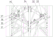
The hoist frame 3 includes a square frame 31, a clamping assembly, and a guide roller assembly.
The centre gripping subassembly includes vertical clamp splice 32 and horizontal yoke plate 33, and the crossroad shape of vertical clamp splice is L shape, and horizontal yoke plate is the L shaped plate, and two horizontal yoke plate parallel connection are in the top and the bottom of vertical clamp splice outer wall, and parallel oval hole has been seted up respectively in the both sides and bight of horizontal yoke plate 33, and the round hole has been seted up respectively to the both sides reason of vertical clamp splice. Rubber backing plates 34 are arranged on the inner walls of two sides of the vertical clamping blocks 32.
The guide roller assembly comprises a yoke plate 35, a double-lug plate seat 36 and a guide roller group 37 hinged between the two lug plates of the yoke plate, wherein a round hole corresponding to the round hole on the horizontal yoke plate 33 is formed in the yoke plate 35, and a round hole corresponding to the round hole on the yoke plate 35 is formed in the bottom plate of the double-lug plate seat 36.
The arrangement of the waist circular holes on the horizontal connecting plate 33 and the double-lug plate seat 36 can respectively ensure that the horizontal position can be adjusted by installing and fixing the horizontal connecting plate and the double-lug plate seat.
Four corners of the lower part of the inner cavity of the derrick are symmetrically connected with horizontal brackets 6, and the horizontal brackets 6 are vertically connected with guide rails 5. The horizontal bracket 6 is arranged at a height based on the standard section height of the holding pole and is used for supporting the lifted and assembled holding pole.
The lifting frame 3 is positioned above the horizontal bracket 6, and when the lifting frame moves, the guide wheel set 37 clamps the guide rail 5 to slide.
Two groups of oil cylinders 4 are symmetrically arranged at the middle positions of a pair of sides of the derrick 2, the lower ends of the oil cylinders are hinged on the middle seat 11 of the base 1, the upper end of a piston rod of each oil cylinder is jacked up to the lifting frame 3, the lower side of the square frame 31 of the lifting frame 3 at the corresponding opposite side is provided with a connecting seat, and the head of each piston rod is hinged with the connecting seat through a pin shaft.
The limit waist ring 7 comprises a square frame 71, a limit pulley assembly and a stay wire fixing tube 74, wherein the limit pulley assembly is connected to the square frame 71 and comprises a mounting frame 72 and guide pulleys 73 hinged to the top and the bottom of the mounting frame, and a limit groove is formed in the middle of each guide pulley.
The limiting waist ring 7 is used for guiding and centering when the holding pole is lifted so as to ensure the stability when the holding pole is lifted.
The concrete steps of this embodiment of pole are embraced in the flip-chip of suspension are as follows:
(1) leveling the ground at the installation position, assembling the base and adjusting the levelness of the base through the supporting legs to meet the requirement;
(2) assembling a derrick, connecting and fixing the lower end of the derrick with a side seat of a base, and installing a lifting frame, a bracket, a guide rail and a limiting waist ring at the specified position of the derrick;
(3) stay wires are respectively fixed at the top of the derrick and four corners of the base to keep the derrick vertical and stable;
(4) installing an oil cylinder;
(5) fixing an external stay wire at the top of the first assembled holding pole standard section, pushing the external stay wire into the derrick, clamping four corners of the holding pole section by a lifting frame, and simultaneously adjusting the center of the holding pole section to coincide with the center of the derrick;
(6) the oil cylinder works, the holding rod standard section is lifted upwards until the next holding rod standard section can be pushed into the derrick, the holding rod standard section lifted in place is supported by the bracket, and an external stay wire ensures that the holding rod standard section is in a vertical state;
(7) pushing the second holding pole standard section into the derrick according to the step (5), assembling the upper end of the holding pole standard section and the lower end of the first holding pole standard section, and retracting the piston rod of the oil cylinder;
(8) repeating the step (6) until all the holding pole standard sections are lifted and assembled in sequence;
(9) and when the top of the standard section of the holding pole exceeds the height of the derrick, hoisting the holding pole conical section through the small holding pole assembly, and finally, hoisting the conical section top cap through the small holding pole assembly.
The small holding pole component comprises a pole body 8 and a pulley HC fixed on the upper end of the pole body. The holding rod conical section and the conical section top cap are fixed through the steel wire rope respectively, the steel wire rope bypasses a tackle at the upper end of the rod body, and the holding rod conical section and the conical section top cap can be lifted to the top of the holding rod from the outside of the derrick to be installed by pulling the steel wire rope.
(10) Fixing an outer bracing wire of the holding pole;
(11) when the holding pole is not lifted off the ground, the derrick, the lifting frame, the bracket, the guide rail and the limiting waist ring are dismantled, so that the installation and construction of a supporting system under the holding pole are facilitated.
The difference between the second embodiment and the first embodiment is that a power device of the jacking device adopts a winching mill, a pulley HC is additionally arranged on the square frame of the lifting frame, a pulley is additionally arranged on the square frame of the limiting waist ring, a pulley is additionally arranged on the base, the pulley on the lifting frame is a lifting pulley, the pulley on the limiting waist ring and the pulley on the base are steering pulleys, and the bearing capacity of the pulley is selected according to needs. The lift cord routing is shown in fig. 7, and the other structure and operation of this embodiment are the same as those of the first embodiment.
When this embodiment suspension flip-chip armful pole, the hank grinds work, and the hoisting rope is with the hoisting frame up-draw, and the hoisting frame centre gripping armful pole segment section promotes, promotes to support through horizontal bracket after targetting in place, then hank grinds reverse work, and the hoisting frame descends the return, then hank grinds forward work again and will next section armful pole promote with last section armful pole butt joint equipment. The other operations of this embodiment are the same as those of the first embodiment.
According to the two embodiments of the invention, the derrick with the reversely-arranged derrick mast is designed, the derrick is divided into a plurality of unit frames, the unit frames are in modular design of the main sheet and the connecting sheet, and the derrick can be quickly assembled on site to replace a tower body reversely-arranged structure.
The lifting mode of the holding pole can flexibly select the mode of jacking the lifting frame by the oil cylinder according to the actual situation on site, and the lifting frame can be lifted by selecting the mode of winching the lifting rope to realize the lifting of the holding pole. The lifting operation is simple, and the grinding mill can rotate forwards or backwards because the piston rod of the oil cylinder is telescopic.
The suspension inverted installation of the holding pole with different plane sizes can be realized by replacing the limiting waist rings with different sizes.
The base is provided with telescopic supporting legs, and the levelness of the base after installation can be adjusted, so that the self-stability of the derrick after resistance is improved.
The derrick can meet the requirement of general assembly of the sectional holding rods with different sections and different lengths for an extra-high voltage tower assembly, and the applicable height of the derrick can be selected and used along with the sectional size of the rod section.
The auxiliary small holding pole is configured, so that the hoisting of the top conical section and the conical section top cap of the holding pole can be facilitated, and the auxiliary hoisting of parts with ultra-large sizes of the holding pole can be facilitated.
The staff is holding pole flip-chip in-process, only need to hold the pole by group and carry out the connection operation between the pole segment from top to bottom, only basically has the installation operation of fastener promptly, and the installation factor is high.
In addition, if the tower material is hoisted by construction before the holding pole is assembled, the pole section flange connecting seat can be replaced by the hinged support seat to hoist the tower material, and the hinged support seat is disassembled and replaced by the flange connecting seat to continue the assembly of the holding pole after the lifting construction of the tower material is completed.
Claims (10)
1. The utility model provides a pole derrick formula flip-chip lift system is embraced in suspension which characterized in that: it includes base, derrick, hoisting device and spacing waist ring, and the derrick is detachable structure of assembling, and its lower extreme can be dismantled with the base and be connected, and hoisting device includes power device and hoisting frame, and hoisting frame and base parallel arrangement are in the lower part of derrick inner chamber, and the pole is embraced in the hoisting frame centre gripping, and power device provides power for the hoisting frame and realizes embracing the pole and promote, and spacing waist ring level is fixed in the top of derrick inner chamber.
2. The suspended derrick type inverted hoisting system as claimed in claim 1, wherein: the base includes well seat and the limit seat of its bilateral symmetry connection, and the central section of well seat is pole section flange joint seat, the both sides of central section are the pole section and enter into the seat, can dismantle the connection through the fastener between well seat and the limit seat, and the four corners symmetric connection of both sides seat has the landing leg of adjustable height.
3. The suspended derrick-type inverted hoisting system as claimed in claim 2, wherein: the derrick comprises a plurality of unit frames which are assembled up and down, each unit frame comprises two main sheets which are opposite in parallel and a connecting sheet which is detachably connected between the two main sheets, adjacent unit frames are detachably connected through a fastener, and the lower end of the first unit frame is symmetrically connected to the side seat; the outer side of the upright post of one of the unit frame main sheets is hinged with a small holding rod component, and the small holding rod component comprises a rod body and a pulley fixed at the upper end of the rod body.
4. The suspended derrick type inverted hoisting system as claimed in claim 3, wherein: the main sheet comprises two upright posts and a connecting rod between the upright posts, flanges are arranged at two ends of each upright post, and ear plates for fixing the connecting sheet are arranged on the same sides of the top and the bottom of each upright post; the connecting piece comprises a horizontal rod and an inclined rod between the horizontal rods, the horizontal rod is arranged in parallel from top to bottom, lug plates corresponding to the lug plates on the stand column are arranged at two ends of the horizontal rod, and the corresponding lug plates are fixedly connected through bolts and nuts.
5. The suspended derrick type inverted hoisting system as claimed in claim 4, wherein: the lifting frame comprises a square frame, a clamping assembly and a guide roller assembly; the clamping assembly comprises vertical clamping blocks and horizontal connecting plates, the cross section of each vertical clamping block is L-shaped, each horizontal connecting plate is an L-shaped plate, the two horizontal connecting plates are connected to the top and the bottom of the outer wall of each vertical clamping block in parallel, two sides and corners of each horizontal connecting plate are respectively provided with parallel waist circular holes, and two side edges of each vertical clamping block are respectively provided with a circular hole; the guide roller assembly comprises a yoke plate, a double-lug plate seat and a guide roller group hinged between the two lug plates, and the bottom surface of the double-lug plate seat is provided with a round hole corresponding to the waist round hole on the horizontal yoke plate;
the inner corners of the inner cavity of the square frame are symmetrically connected with clamping components;
the top surface and the bottom surface of the four corners of the square frame are respectively connected with a guide roller component extending out of the outer edge of the square frame;
the outer sides of a pair of frameworks of the square framework are symmetrically connected with pulleys.
6. The suspended derrick type inverted hoisting system as claimed in claim 5, wherein: four corners of the lower part of the inner cavity of the derrick are symmetrically provided with horizontal brackets, and lifting guide rails are vertically connected to the horizontal brackets; the lifting frame is positioned above the horizontal bracket, and the guide wheel set clamps the lifting guide rail to slide.
7. The suspended derrick type inverted hoisting system as claimed in claim 6, wherein: the limiting waist ring comprises a square frame, and a limiting pulley assembly, a pulley and a stay wire fixing pipe which are connected to the square frame, wherein the limiting pulley assembly comprises a mounting frame and guide pulleys hinged to the top and the bottom of the mounting frame, a limiting groove is formed in the middle of each guide pulley, and the position and the number of the pulleys correspond to those of the pulleys on the lifting frame.
8. The suspended derrick type inverted hoisting system as claimed in claim 7, wherein: the power device is oil cylinders, two groups of oil cylinders are vertically arranged on two sides of the derrick, the lower end of a cylinder body is hinged on the side seat, the corresponding side of the square frame is provided with a hinged seat, and the upper end of a piston rod of each oil cylinder is hinged and fixed with the hinged seat through a pin shaft to lift the lifting frame upwards;
or the power device is a winching machine, the side seat is provided with a pulley which is upward corresponding to the lifting frame and the limiting waist ring, and the winching machine lifts the lifting frame upwards through the lifting rope and the pulley.
9. A method for inversely installing a holding pole by using the system as claimed in claim 1, wherein the power device of the jacking device adopts an oil cylinder, and the method comprises the following steps:
(1) leveling the ground at the installation position, assembling the base and adjusting the levelness of the base through the supporting legs to meet the requirement;
(2) assembling a derrick, connecting and fixing the lower end of the derrick with a side seat of a base, and installing a lifting frame, a bracket, a guide rail and a limiting waist ring at the specified position of the derrick;
(3) stay wires are respectively fixed at the top of the derrick and four corners of the base to keep the derrick vertical and stable;
(4) installing an oil cylinder;
(5) fixing an external stay wire at the top of the first assembled holding pole standard section, pushing the external stay wire into the derrick, clamping four corners of the holding pole section by a lifting frame, and simultaneously adjusting the center of the holding pole section to coincide with the center of the derrick;
(6) the oil cylinder works, the holding rod standard section is lifted upwards until the next holding rod standard section can be pushed into the derrick, the holding rod standard section lifted in place is supported by the bracket, and an external stay wire ensures that the holding rod standard section is in a vertical state;
(7) pushing the second holding pole standard section into the derrick according to the step (5), assembling the upper end of the holding pole standard section and the lower end of the first holding pole standard section, and retracting the piston rod of the oil cylinder;
(8) repeating the step (6) until all the holding pole standard sections are lifted and assembled in sequence;
(9) when the top of the derrick standard section exceeds the height of the derrick, the derrick conical section is lifted through the small derrick and finally the derrick conical section top cap is lifted through the small derrick;
(10) fixing an outer bracing wire of the holding pole;
(11) when the holding pole is not lifted off the ground, the derrick, the lifting frame, the bracket, the guide rail and the limiting waist ring are dismantled, so that the installation and construction of a supporting system under the holding pole are facilitated.
10. A method for inversely installing a holding pole by using the system as claimed in claim 1, wherein the power device of the jacking device adopts a grinder, and the method comprises the following steps:
(1) leveling the ground at the installation position, assembling the base and adjusting the levelness of the base through the supporting legs to meet the requirement;
(2) assembling a derrick, connecting and fixing the lower end of the derrick with a side seat of a base, and installing a lifting frame, a bracket, a guide rail and a limiting waist ring at the specified position of the derrick;
(3) stay wires are respectively fixed at the top of the derrick and four corners of the base to keep the derrick vertical and stable;
(4) a lifting rope is laid on the base, the lifting frame and the pulley on the limiting waist ring, and the lifting rope is connected with the winching;
(5) fixing an external stay wire at the top of the first assembled holding pole standard section, pushing the external stay wire into the derrick, clamping four corners of the holding pole section by a lifting frame, and simultaneously adjusting the center of the holding pole section to coincide with the center of the derrick;
(6) winching, namely lifting the pole standard section upwards until the next pole standard section can be pushed into the derrick, supporting the pole standard section lifted in place through a bracket, and ensuring that the pole standard section is in a vertical state through an external stay wire;
(7) pushing the second holding pole standard section into the derrick according to the step (5), assembling the upper end of the holding pole standard section and the lower end of the first holding pole standard section, performing winching and grinding in a reverse direction, and descending the lifting frame to return;
(8) repeating the step (6) until all the holding pole standard sections are lifted and assembled in sequence;
(9) when the top of the derrick standard section exceeds the height of the derrick, the derrick conical section is lifted through the small derrick and finally the derrick conical section top cap is lifted through the small derrick;
(10) fixing an outer bracing wire of the holding pole;
(11) when the holding pole is not lifted off the ground, the derrick, the lifting frame, the bracket, the guide rail and the limiting waist ring are dismantled, so that the installation and construction of a supporting system under the holding pole are facilitated.
Priority Applications (1)
| Application Number | Priority Date | Filing Date | Title |
|---|---|---|---|
| CN202011598887.0A CN112832579A (en) | 2020-12-29 | 2020-12-29 | Suspension derrick type inverted lifting system and application method thereof |
Applications Claiming Priority (1)
| Application Number | Priority Date | Filing Date | Title |
|---|---|---|---|
| CN202011598887.0A CN112832579A (en) | 2020-12-29 | 2020-12-29 | Suspension derrick type inverted lifting system and application method thereof |
Publications (1)
| Publication Number | Publication Date |
|---|---|
| CN112832579A true CN112832579A (en) | 2021-05-25 |
Family
ID=75925211
Family Applications (1)
| Application Number | Title | Priority Date | Filing Date |
|---|---|---|---|
| CN202011598887.0A Pending CN112832579A (en) | 2020-12-29 | 2020-12-29 | Suspension derrick type inverted lifting system and application method thereof |
Country Status (1)
| Country | Link |
|---|---|
| CN (1) | CN112832579A (en) |
Cited By (2)
| Publication number | Priority date | Publication date | Assignee | Title |
|---|---|---|---|---|
| CN113585860A (en) * | 2021-09-02 | 2021-11-02 | 扬州国电通用电力机具制造有限公司 | Device and method for mounting and dismounting double-arm holding pole |
| CN114251009A (en) * | 2021-12-31 | 2022-03-29 | 江苏省送变电有限公司 | Holding pole standard knot in-place device and introducing and leading-out method thereof |
-
2020
- 2020-12-29 CN CN202011598887.0A patent/CN112832579A/en active Pending
Cited By (2)
| Publication number | Priority date | Publication date | Assignee | Title |
|---|---|---|---|---|
| CN113585860A (en) * | 2021-09-02 | 2021-11-02 | 扬州国电通用电力机具制造有限公司 | Device and method for mounting and dismounting double-arm holding pole |
| CN114251009A (en) * | 2021-12-31 | 2022-03-29 | 江苏省送变电有限公司 | Holding pole standard knot in-place device and introducing and leading-out method thereof |
Similar Documents
| Publication | Publication Date | Title |
|---|---|---|
| CN112832579A (en) | Suspension derrick type inverted lifting system and application method thereof | |
| CN110700572B (en) | Height-adjustable supporting base and using method thereof | |
| CN102146729B (en) | Easily-assembled and disassembled umbrella-shaped platform for top construction in spherical container and use method thereof | |
| CN214576154U (en) | Suspension derrick type inverted lifting system | |
| CN111891977B (en) | Transformer installation lifting device and matched construction method | |
| CN219280494U (en) | Tower beam temporary consolidation supporting structure for bridge tower stability control | |
| US4205826A (en) | Lifting and supporting apparatus for a tower crane | |
| CN211078166U (en) | Pipeline vertical hoisting device | |
| CN113309256A (en) | Construction device and construction method for prefabricated shear wall with post-pouring section | |
| CN211142890U (en) | Novel lifting height-limiting rod | |
| CN104210990B (en) | Hydraulic jacking type inversed lifting frame | |
| CN220149061U (en) | Quick lifting support for adjustable sliding rail in bin | |
| CN218061317U (en) | Supporting device for installing welding ball net rack | |
| CN111305433A (en) | Construction structure and construction method of inclined glass curtain wall of roof steel structure platform | |
| CN210505352U (en) | A machines and tools for construction of LOFT steel construction | |
| CN213834248U (en) | Adjustable steel beam connecting plate mounting frame body | |
| CN112412152B (en) | Construction method of underslung derrick-free variable-section rectangular chimney support system | |
| CN219194443U (en) | Repair operation platform with adjustable height | |
| CN219194326U (en) | Highway bridge slope adjustment jacking structure | |
| CN214996550U (en) | Adjustable telegraph pole correction device | |
| CN211889641U (en) | Combined clamping fixture for boiler railing | |
| CN220059026U (en) | A can assemble, adjustable interim fixed stay device for steel construction hoist and mount | |
| CN215484514U (en) | Lifting scaffold | |
| CN214495436U (en) | Can fix hoist and mount cable shaft cover formula electric hoist | |
| CN216007789U (en) | Climbing mechanism of ultrahigh chimney slip form operation platform |
Legal Events
| Date | Code | Title | Description |
|---|---|---|---|
| PB01 | Publication | ||
| PB01 | Publication | ||
| SE01 | Entry into force of request for substantive examination | ||
| SE01 | Entry into force of request for substantive examination |