CN112828552B - Intelligent butt joint method and system for flange parts - Google Patents
Intelligent butt joint method and system for flange parts Download PDFInfo
- Publication number
- CN112828552B CN112828552B CN202110127376.9A CN202110127376A CN112828552B CN 112828552 B CN112828552 B CN 112828552B CN 202110127376 A CN202110127376 A CN 202110127376A CN 112828552 B CN112828552 B CN 112828552B
- Authority
- CN
- China
- Prior art keywords
- flange
- point cloud
- module
- face
- normal vector
- Prior art date
- Legal status (The legal status is an assumption and is not a legal conclusion. Google has not performed a legal analysis and makes no representation as to the accuracy of the status listed.)
- Active
Links
Images


Classifications
-
- B—PERFORMING OPERATIONS; TRANSPORTING
- B23—MACHINE TOOLS; METAL-WORKING NOT OTHERWISE PROVIDED FOR
- B23P—METAL-WORKING NOT OTHERWISE PROVIDED FOR; COMBINED OPERATIONS; UNIVERSAL MACHINE TOOLS
- B23P19/00—Machines for simply fitting together or separating metal parts or objects, or metal and non-metal parts, whether or not involving some deformation; Tools or devices therefor so far as not provided for in other classes
-
- B—PERFORMING OPERATIONS; TRANSPORTING
- B25—HAND TOOLS; PORTABLE POWER-DRIVEN TOOLS; MANIPULATORS
- B25J—MANIPULATORS; CHAMBERS PROVIDED WITH MANIPULATION DEVICES
- B25J9/00—Program-controlled manipulators
- B25J9/16—Program controls
- B25J9/1694—Program controls characterised by use of sensors other than normal servo-feedback from position, speed or acceleration sensors, perception control, multi-sensor controlled systems, sensor fusion
- B25J9/1697—Vision controlled systems
-
- G—PHYSICS
- G06—COMPUTING OR CALCULATING; COUNTING
- G06F—ELECTRIC DIGITAL DATA PROCESSING
- G06F30/00—Computer-aided design [CAD]
- G06F30/20—Design optimisation, verification or simulation
-
- G—PHYSICS
- G06—COMPUTING OR CALCULATING; COUNTING
- G06T—IMAGE DATA PROCESSING OR GENERATION, IN GENERAL
- G06T3/00—Geometric image transformations in the plane of the image
- G06T3/08—Projecting images onto non-planar surfaces, e.g. geodetic screens
-
- G—PHYSICS
- G06—COMPUTING OR CALCULATING; COUNTING
- G06T—IMAGE DATA PROCESSING OR GENERATION, IN GENERAL
- G06T5/00—Image enhancement or restoration
- G06T5/70—Denoising; Smoothing
-
- G—PHYSICS
- G06—COMPUTING OR CALCULATING; COUNTING
- G06T—IMAGE DATA PROCESSING OR GENERATION, IN GENERAL
- G06T7/00—Image analysis
- G06T7/70—Determining position or orientation of objects or cameras
- G06T7/73—Determining position or orientation of objects or cameras using feature-based methods
-
- G—PHYSICS
- G06—COMPUTING OR CALCULATING; COUNTING
- G06F—ELECTRIC DIGITAL DATA PROCESSING
- G06F2111/00—Details relating to CAD techniques
- G06F2111/04—Constraint-based CAD
-
- G—PHYSICS
- G06—COMPUTING OR CALCULATING; COUNTING
- G06T—IMAGE DATA PROCESSING OR GENERATION, IN GENERAL
- G06T2207/00—Indexing scheme for image analysis or image enhancement
- G06T2207/10—Image acquisition modality
- G06T2207/10028—Range image; Depth image; 3D point clouds
-
- G—PHYSICS
- G06—COMPUTING OR CALCULATING; COUNTING
- G06T—IMAGE DATA PROCESSING OR GENERATION, IN GENERAL
- G06T2207/00—Indexing scheme for image analysis or image enhancement
- G06T2207/30—Subject of image; Context of image processing
- G06T2207/30108—Industrial image inspection
- G06T2207/30164—Workpiece; Machine component
Landscapes
- Engineering & Computer Science (AREA)
- Physics & Mathematics (AREA)
- Theoretical Computer Science (AREA)
- General Physics & Mathematics (AREA)
- Mechanical Engineering (AREA)
- Computer Vision & Pattern Recognition (AREA)
- Computer Hardware Design (AREA)
- Evolutionary Computation (AREA)
- Geometry (AREA)
- General Engineering & Computer Science (AREA)
- Robotics (AREA)
- Length Measuring Devices By Optical Means (AREA)
Abstract
本发明属于智能装配技术领域,并具体公开了一种法兰零件智能对接方法及系统,其包括步骤:S1、获取待对接法兰零件的点云图像,从点云图像中分离出两个法兰端面,进而分离得到两个法兰圆柱面;S2、将两个法兰端面进行拟合,并拟合法兰端面边界圆,进而得到法兰端面圆心坐标和法矢量初值;S3、将两个法兰圆柱面投影至已拟合的法兰端面上,并对法兰圆柱面进行去噪,将投影、去噪后的法兰圆柱面进行拟合,进而计算得到最终圆心坐标和法矢量;S4、根据最终圆心坐标和法矢量,移动待对接法兰零件,完成法兰零件智能对接。本发明可实现法兰类零部件空间位置和姿态的高精度识别定位和快速调整,极大提高了对接装配工作的效率和精度。
The invention belongs to the technical field of intelligent assembly, and specifically discloses a method and system for intelligent docking of flange parts, which comprises the steps of: S1. Acquire a point cloud image of flange parts to be docked, and separate two methods from the point cloud image. Flange end face, and then separate to obtain two flange cylindrical surfaces; S2, Fit the two flange end faces, and fit the flange end face boundary circle, and then obtain the flange end face circle center coordinates and the initial value of the normal vector; S3, Fit the two flange end faces The flange cylindrical surface is projected onto the fitted flange end face, the flange cylindrical surface is denoised, the projection and denoised flange cylindrical surface is fitted, and the final circle center coordinates and normal vector are calculated. ; S4. According to the final circle center coordinates and normal vector, move the flange parts to be butted to complete the intelligent docking of flange parts. The invention can realize high-precision identification, positioning and rapid adjustment of the spatial position and attitude of flange-like components, and greatly improves the efficiency and accuracy of the butt assembly work.
Description
技术领域technical field
本发明属于智能装配技术领域,更具体地,涉及一种法兰零件智能对接方法及系统。The invention belongs to the technical field of intelligent assembly, and more particularly, relates to a method and system for intelligent docking of flange parts.
背景技术Background technique
船舶大型推进轴系的对接装配是船舶建造的重要环节之一,对于最终安装质量具有重要影响。近年来,对船舶大型推进轴系也有了更高的装配精度和装配自动化、智能化的要求。引入视觉测量系统可以高精度测量船舶轴系对接法兰的空间相对位置和姿态,引入伺服控制系统可以高精度快速调整船舶轴系的空间位置和姿态,进而可以满足更高精度的装配需求。The docking assembly of the large-scale propulsion shafting of ships is one of the important links in ship construction, which has an important impact on the final installation quality. In recent years, there have also been higher assembly precision and assembly automation and intelligent requirements for the large-scale propulsion shafting of ships. The introduction of the visual measurement system can measure the relative spatial position and attitude of the docking flange of the ship's shafting with high precision, and the introduction of the servo control system can quickly adjust the spatial position and attitude of the ship's shafting with high precision, thereby meeting higher-precision assembly requirements.
目前船舶轴系的对接装配过程普遍采用人工吊装的方式,借用龙门吊来辅助人工精确定位,再通过百分表测量当前轴系的偏移曲折值,然后人工调整调节螺栓来精确控制轴系位置和姿态,以使轴系达到符合要求的安装精度。这种安装方式作业周期长,费时费力,存在安全隐患。At present, the docking and assembling process of ship shafting generally adopts the method of manual hoisting. The gantry crane is used to assist manual precise positioning, and then the offset and bending value of the current shafting is measured by the dial indicator, and then the adjustment bolts are manually adjusted to accurately control the position of the shafting. attitude, so that the shafting can meet the required installation accuracy. This installation method has a long operation cycle, is time-consuming and labor-intensive, and has potential safety hazards.
发明内容SUMMARY OF THE INVENTION
针对现有技术的以上缺陷或改进需求,本发明提供了一种法兰零件智能对接方法及系统,其目的在于,以法兰圆柱面在拟合平面上的投影圆拟合之后的圆心来描述准确的法兰位置,实现法兰零件空间位置和姿态的高精度识别定位和快速调整,提高对接装配工作的效率和精度。In view of the above defects or improvement requirements of the prior art, the present invention provides an intelligent docking method and system for flange parts. Accurate flange position, realize high-precision identification, positioning and rapid adjustment of the spatial position and attitude of flange parts, and improve the efficiency and accuracy of butt assembly work.
为实现上述目的,按照本发明的一方面,提出了一种法兰零件智能对接方法,包括如下步骤:In order to achieve the above purpose, according to one aspect of the present invention, a method for intelligent butt jointing of flange parts is proposed, comprising the following steps:
S1、获取待对接法兰零件的点云图像,从点云图像中分离出两个法兰端面,进而分离得到两个法兰圆柱面;S1. Obtain a point cloud image of the flange part to be butted, separate two flange end faces from the point cloud image, and then separate to obtain two flange cylindrical faces;
S2、将两个法兰端面进行拟合,并拟合法兰端面边界圆,进而得到法兰端面圆心坐标和法矢量初值;S2. Fit the two flange end faces, and fit the boundary circle of the flange end face, and then obtain the coordinates of the center of the flange end face and the initial value of the normal vector;
S3、根据法兰端面法矢量初值,将两个法兰圆柱面投影至已拟合的法兰端面上;根据法兰圆柱面与法兰端面圆心坐标的距离,对法兰圆柱面进行去噪;将投影、去噪后的法兰圆柱面进行拟合,进而计算得到最终圆心坐标和法矢量;S3. According to the initial value of the normal vector of the flange end face, project the two flange cylindrical surfaces onto the fitted flange end surface; Noise; Fit the flange cylinder surface after projection and denoising, and then calculate the final circle center coordinates and normal vector;
S4、根据最终圆心坐标和法矢量,移动待对接法兰零件,完成法兰零件智能对接。S4. According to the final circle center coordinates and normal vector, move the flange parts to be butted to complete the intelligent docking of flange parts.
作为进一步优选的,获取待对接法兰零件的点云图像具体为:通过机械臂带动激光三维扫描仪对待对接法兰零件进行扫描,得到法兰零件的点云图像。As a further preferred method, acquiring the point cloud image of the flange part to be butted is specifically as follows: driving a laser 3D scanner to scan the flange part to be butted by a robotic arm to obtain a point cloud image of the flange part.
作为进一步优选的,激光三维扫描仪的扫描路径根据如下步骤确定:As a further preference, the scanning path of the laser 3D scanner is determined according to the following steps:
(1)建立扫描路径规划目标函数PI(dj,βj):(1) Establish the scanning path planning objective function P I (d j ,β j ):

其中,
(2)确定约束条件:(2) Determine the constraints:


其中,i=1,2;dj(djx,djy,djz)为机械臂末端位置,βj(βjx,βjy,βjz)为机械臂末端姿态,Dmax、Dmin分别为激光三维扫描仪最远有效扫描范围和最近有效扫描范围,t为法兰零件厚度,R、r分别为法兰零件的直径和轴径,sl为激光三维扫描仪最远有效扫描范围下的成像边长;Among them, i=1,2; d j (d jx , d jy , d jz ) is the position of the end of the robot arm, β j (β jx , β jy , β jz ) is the posture of the end of the robot arm, D max and D min respectively is the farthest effective scanning range and the nearest effective scanning range of the laser 3D scanner, t is the thickness of the flange part, R and r are the diameter and shaft diameter of the flange part respectively, and sl is the farthest effective scanning range of the laser 3D scanner. imaging side length;
(3)根据约束条件,对扫描路径规划目标函数进行求解,得到激光三维扫描仪的扫描路径。(3) According to the constraints, the scanning path planning objective function is solved to obtain the scanning path of the laser 3D scanner.
作为进一步优选的,所述步骤S1中,根据曲率一致性从点云图像中分离出两个法兰端面,再根据与法兰端面的空间距离关系分离出两个法兰圆柱面。As a further preference, in the step S1, the two flange end faces are separated from the point cloud image according to the curvature consistency, and then the two flange cylindrical faces are separated according to the spatial distance relationship with the flange end faces.
作为进一步优选的,获取待对接法兰零件的点云图像后,先根据点云的空间邻近度和曲率相似度对点云图像数据进行去噪处理,然后再进行法兰端面分离。As a further preference, after acquiring the point cloud image of the flange part to be butted, first perform denoising processing on the point cloud image data according to the spatial proximity and curvature similarity of the point cloud, and then separate the flange end faces.
按照本发明的另一方面,提供了一种用于实现上述法兰零件智能对接方法的系统,包括图像采集装置、图像处理装置和运动控制装置,其中:According to another aspect of the present invention, a system for realizing the above-mentioned intelligent docking method for flange parts is provided, comprising an image acquisition device, an image processing device and a motion control device, wherein:
所述图像采集装置用于采集待对接法兰零件的点云图像;The image acquisition device is used for acquiring point cloud images of flange parts to be butted;
所述图像处理装置包括点云去噪模块、平面曲面分离模块、平面拟合模块和曲面拟合模块,其中,所述点云去噪模块用于对点云图像数据进行去噪处理,所述平面曲面分离模块用于从去噪后的点云图像中分离出法兰端面和法兰圆柱面,所述平面拟合模块用于对法兰端面进行拟合,所述曲面拟合模块用于将法兰圆柱面投影到拟合的法兰端面上,并拟合投影后的法兰圆柱面,得到最终圆心坐标和法矢量;The image processing device includes a point cloud denoising module, a plane surface separation module, a plane fitting module and a surface fitting module, wherein the point cloud denoising module is used for denoising the point cloud image data, and the The plane surface separation module is used to separate the flange end face and the flange cylindrical surface from the denoised point cloud image, the plane fitting module is used to fit the flange end face, and the surface fitting module is used to Project the flange cylindrical surface onto the fitted flange end face, and fit the projected flange cylindrical surface to obtain the final circle center coordinates and normal vector;
所述运动控制装置用于根据最终圆心坐标和法矢量,移动待对接法兰零件至目标位置。The motion control device is used to move the flange part to be butted to the target position according to the final circle center coordinate and normal vector.
作为进一步优选的,所述运动控制装置包括控制模块、六通道伺服驱动器和两套并联的三轴运动机构,其中,所述控制模块用于将最终圆心坐标和法矢量转化成所述三轴运动机构的运动量,并基于该运动量生成位置速度控制信号;所述六通道伺服驱动器用于根据位置速度控制信号控制所述三轴运动机构带动法兰零件运动至目标位置。As a further preference, the motion control device includes a control module, a six-channel servo driver and two sets of parallel three-axis motion mechanisms, wherein the control module is used to convert the final circle center coordinates and normal vector into the three-axis motion The movement amount of the mechanism, and the position and speed control signal is generated based on the movement amount; the six-channel servo driver is used to control the three-axis movement mechanism to drive the flange part to the target position according to the position and speed control signal.
作为进一步优选的,所述运动控制装置还包括锁定模块,所述锁定模块设置在所述三轴运动机构的伺服电机中,用于在完成对接后,防止因外力导致伺服电机中电动缸的活塞杆缩回;所述运动控制装置采用绝对式编码器。As a further preference, the motion control device further includes a locking module, which is arranged in the servo motor of the three-axis motion mechanism, and is used to prevent the piston of the electric cylinder in the servo motor from being caused by external force after the docking is completed. The rod retracts; the motion control uses an absolute encoder.
作为进一步优选的,所述图像采集装置包括激光三维扫描仪,该激光三维扫描仪通过机械臂带动或直接手动操作。As a further preference, the image acquisition device includes a three-dimensional laser scanner, which is driven by a mechanical arm or directly operated manually.
作为进一步优选的,还包括手动测量对接装置,该手动测量对接装置包括两组百分表,每组百分表按180°对称安装在待对接法兰零件上。As a further preference, it also includes a manual measurement docking device, the manual measurement docking device includes two sets of dial indicators, and each set of dial indicators is symmetrically installed on the flange parts to be butted according to 180°.
总体而言,通过本发明所构思的以上技术方案与现有技术相比,主要具备以下的技术优点:In general, compared with the prior art, the above technical solutions conceived by the present invention mainly have the following technical advantages:
1.本发明针对法兰零件结构特性,由于端面边界圆的样本数量少,并且存在倒角,扫描时存在较大误差,所以不以端面边界圆圆心来描述对接法兰的位置,而以法兰圆柱面在拟合平面上的投影圆拟合之后的圆心来描述准确的法兰位置;本发明可以实现法兰零件空间位置和姿态的高精度识别定位和快速调整,极大地提高了对接装配工作的效率和精度,可以广泛应用于船舶、航空航天、管道运输等领域。1. The present invention is aimed at the structural characteristics of flange parts. Due to the small number of samples of the end face boundary circle and the existence of chamfers, there is a large error during scanning, so the position of the butt flange is not described by the center of the end face boundary circle, but the method The accurate flange position can be described by the center of the projection circle of the blue cylindrical surface on the fitting plane after fitting; the invention can realize high-precision identification, positioning and quick adjustment of the spatial position and attitude of flange parts, and greatly improve the butt assembly. The efficiency and precision of work can be widely used in shipping, aerospace, pipeline transportation and other fields.
2.本发明采用无接触式视觉测量方式。基于双目视觉成像原理,通过所述手持式激光三维扫描仪对所述法兰零件进行扫描成像,准确测量所述法兰零件的空间位置和姿态,解决了目前人工测量精度差的问题。2. The present invention adopts a non-contact visual measurement method. Based on the principle of binocular vision imaging, the flange part is scanned and imaged by the handheld laser three-dimensional scanner, and the spatial position and attitude of the flange part are accurately measured, which solves the problem of poor manual measurement accuracy at present.
3.本发明采用多约束路径规划技术。基于运动学分析方法,进行多约束路径规划,求解最优扫描路径,扫描时间可控制在7分钟内,解决了目前人工测量效率低的问题。3. The present invention adopts the multi-constrained path planning technology. Based on the kinematic analysis method, multi-constrained path planning is carried out to solve the optimal scanning path, and the scanning time can be controlled within 7 minutes, which solves the problem of low efficiency of manual measurement at present.
4.本发明采用多种工作模式以适用不同的工作环境和要求。系统具备自动扫描对接、手动扫描对接和手动测量对接三种功能:自动扫描对接功能可自动实现所述法兰零件的对接装配工作;手动扫描对接功能可用于当狭小工作环境下无法布置所述六轴机械臂时,实现所述法兰零件的对接装配工作;手动测量对接功能可用于当前工作环境无法使用所述手持式激光三维扫描仪或目标对象为不带法兰的圆柱形零部件的工作情境。4. The present invention adopts a variety of working modes to adapt to different working environments and requirements. The system has three functions: automatic scanning docking, manual scanning docking and manual measurement docking: the automatic scanning docking function can automatically realize the docking and assembling work of the flange parts; the manual scanning docking function can be used when it is impossible to arrange the six parts in a narrow working environment. When the robot arm is rotated, the docking and assembling work of the flange parts can be realized; the manual measurement docking function can be used for the work where the hand-held laser 3D scanner cannot be used in the current working environment or the target object is cylindrical parts without flanges situation.
5.本发明采用伺服驱动控制方式。所述运动控制装置采用伺服驱动控制方式,控制所述三轴运动机构运动,控制精度可达0.01mm,解决了目前人工吊装定位精度差、效率低的问题。5. The present invention adopts the servo drive control mode. The motion control device adopts a servo drive control mode to control the motion of the three-axis motion mechanism, and the control accuracy can reach 0.01 mm, which solves the problems of poor positioning accuracy and low efficiency of the current manual hoisting.
附图说明Description of drawings
图1为本发明实施例法兰零件智能对接系统结构示意图;1 is a schematic structural diagram of an intelligent docking system for flange parts according to an embodiment of the present invention;
图2为本发明实施例法兰零件智能对接系统结构右视图;2 is a right side view of the structure of the intelligent docking system for flange parts according to an embodiment of the present invention;
图3为本发明实施例手动测量功能结构示意图;3 is a schematic structural diagram of a manual measurement function according to an embodiment of the present invention;
图4为本发明实施例手动测量功能结构前视图;Fig. 4 is the front view of the manual measurement function structure according to the embodiment of the present invention;
图5为本发明实施例中各装置连接示意图;5 is a schematic diagram of the connection of each device in the embodiment of the present invention;
图6为本发明实施例中图像采集装置模块示意图;6 is a schematic diagram of a module of an image acquisition device in an embodiment of the present invention;
图7为本发明实施例中图像处理装置模块示意图;7 is a schematic diagram of a module of an image processing apparatus in an embodiment of the present invention;
图8为本发明实施例中运动控制装置模块示意图;8 is a schematic diagram of a module of a motion control device in an embodiment of the present invention;
图9为本发明实施例法兰零件智能对接方法流程图。FIG. 9 is a flow chart of a method for intelligent docking of flange parts according to an embodiment of the present invention.
在所有附图中,相同的附图标记用来表示相同的元件或结构,其中:Throughout the drawings, the same reference numbers are used to refer to the same elements or structures, wherein:
1-图像采集装置,2-图像处理装置,3-运动控制装置,4-百分表。1- image acquisition device, 2- image processing device, 3- motion control device, 4- dial indicator.
具体实施方式Detailed ways
为了使本发明的目的、技术方案及优点更加清楚明白,以下结合附图及实施例,对本发明进行进一步详细说明。应当理解,此处所描述的具体实施例仅仅用以解释本发明,并不用于限定本发明。此外,下面所描述的本发明各个实施方式中所涉及到的技术特征只要彼此之间未构成冲突就可以相互组合。In order to make the objectives, technical solutions and advantages of the present invention clearer, the present invention will be further described in detail below with reference to the accompanying drawings and embodiments. It should be understood that the specific embodiments described herein are only used to explain the present invention, but not to limit the present invention. In addition, the technical features involved in the various embodiments of the present invention described below can be combined with each other as long as they do not conflict with each other.
本发明实施例提供的一种法兰零件智能对接系统,如图1、图2和图5所示,包括图像采集装置1、图像处理装置2和运动控制装置3,其中:An intelligent docking system for flange parts provided by an embodiment of the present invention, as shown in FIG. 1 , FIG. 2 and FIG. 5 , includes an image acquisition device 1 , an image processing device 2 and a motion control device 3 , wherein:
所述图像采集装置1设置于法兰零件的一侧,如图6所示,包括手持式激光三维扫描仪11和六轴机械臂12,其中,所述手持式激光三维扫描仪11包括激光发射器111和双目视觉传感器112,所述激光发射器111发射激光,照射在所述法兰零件表面,所述双目视觉传感器112捕捉反射回来的激光,以获取所述法兰零件的图像数据;所述手持式激光三维扫描仪11安装于所述六轴机械臂12末端夹具中,所述六轴机械臂12根据预编程序按照预定路径携带所述手持式激光三维扫描仪11对所述法兰零件进行扫描。The image acquisition device 1 is arranged on one side of the flange part, as shown in FIG. 6 , and includes a handheld laser 3D scanner 11 and a six-axis robotic arm 12 , wherein the handheld laser 3D scanner 11 includes laser emission 111 and a binocular vision sensor 112, the laser transmitter 111 emits laser light and irradiates the surface of the flange part, and the binocular vision sensor 112 captures the reflected laser light to obtain the image data of the flange part ; The handheld laser 3D scanner 11 is installed in the end fixture of the six-axis robotic arm 12, and the six-axis robotic arm 12 carries the handheld laser three-dimensional scanner 11 according to a pre-programmed path according to a predetermined path. Flange parts are scanned.
所述图像处理装置2设置于主控制台内,与所述图像采集装置1连接,如图7所示,所述图像处理装置2包括依次连接的显示模块21、存储模块22、读取模块23、点云去噪模块24、平面曲面分离模块25、平面拟合模块26和曲面拟合模块27,其中:The image processing device 2 is arranged in the main console and is connected to the image acquisition device 1. As shown in FIG. 7 , the image processing device 2 includes a display module 21, a storage module 22, and a reading module 23 connected in sequence. , point cloud denoising module 24, plane surface separation module 25, plane fitting module 26 and surface fitting module 27, wherein:
显示模块21用于实时显示所述图像数据;The display module 21 is used to display the image data in real time;
存储模块22用于按照STL文件格式存储图像数据至指定系统路径下;The storage module 22 is used for storing the image data to the specified system path according to the STL file format;
读取模块23用于从所述指定系统路径下读取所述图像数据;The reading module 23 is used to read the image data from the specified system path;
点云去噪模块24用于根据点云的空间邻近度和曲率相似度对所述图像数据进行去噪处理,得到去噪图像数据;具体的,其去噪滤波算法为:The point cloud denoising module 24 is used to perform denoising processing on the image data according to the spatial proximity and curvature similarity of the point cloud to obtain denoised image data; specifically, the denoising filtering algorithm is:

其中,

其中,∑累加空间为pj∈Nk(pi),nj为点pi的邻域点pj的法矢量,Wc,Ws分别为空间域权重函数和特征域权重函数。Among them, the accumulation space of ∑ is p j ∈ N k (pi ), n j is the normal vector of the neighborhood point p j of point p i , W c , W s are the spatial domain weight function and the feature domain weight function respectively.
平面曲面分离模块25用于根据曲率一致性分离出所述去噪图像数据的法兰端面,再根据与所述法兰端面的空间距离关系分离出法兰圆柱面。The plane and curved surface separation module 25 is used to separate the flange end face of the denoised image data according to the curvature consistency, and then separate the flange cylindrical face according to the spatial distance relationship with the flange end face.
平面拟合模块26用于拟合所述法兰端面,并拟合所述法兰端面边界圆,初步计算所述法兰端面圆心坐标和法矢量;具体的,设定拟合平面方程为:The plane fitting module 26 is used for fitting the flange end face, fitting the flange end face boundary circle, and preliminarily calculating the center coordinates and normal vector of the flange end face; specifically, the fitting plane equation is set as:
ax+by+cz+d=0ax+by+cz+d=0
式中,a2+b2+c2=1;In the formula, a 2 +b 2 +c 2 =1;
根据法兰端面点云数据的空间坐标,可求得点云平均坐标

与拟合平面方程相减,可得:Subtracting from the fitted plane equation, we get:

根据拟合平面与所有点的距离之和最小,令
min(f(a,b,c))=min(‖AX‖)min(f(a,b,c))=min(‖AX‖)
对A进行奇异值分解,得Singular value decomposition of A, we get
A=UDVT A=UDV T
式中,U为n×n的酉矩阵,D为n×3的对角矩阵,V为3×3的酉矩阵;In the formula, U is an n×n unitary matrix, D is an n×3 diagonal matrix, and V is a 3×3 unitary matrix;
因此,‖AX‖=‖UDVTX‖=‖DVTX‖,其中‖VTX‖=‖X‖=1;当且仅当X满足下式时,Therefore, ‖AX‖=‖UDV T X‖=‖DV T X‖, where ‖V T X‖=‖X‖=1; if and only if X satisfies the following formula,

‖AX‖取最小值,从而得到a、b、c的值,代入下式:‖AX‖ takes the minimum value to obtain the values of a, b, and c, and substitute them into the following formula:

即可求得d的值,即得到拟合平面方程。The value of d can be obtained, that is, the fitted plane equation can be obtained.
曲面拟合模块27与所述平面拟合模块26和所述平面曲面分离模块25连接,用于根据法兰端面法矢量初值,确定法兰圆柱面的投影方向,将两个法兰圆柱面投影至已拟合的法兰端面上;根据法兰圆柱面与法兰端面圆心坐标的距离,将法兰圆柱面内距离小于阈值的点去除,从而对法兰圆柱面进行去噪;将投影、去噪后的法兰圆柱面进行拟合,进而计算得到最终圆心坐标和法矢量;具体的,拟合法兰圆柱面时,设定拟合圆方程为:The curved surface fitting module 27 is connected with the plane fitting module 26 and the plane curved surface separation module 25, and is used to determine the projection direction of the flange cylindrical surface according to the initial value of the normal vector of the flange end face, and connect the two flange cylindrical surfaces. Projected to the flange end face that has been fitted; according to the distance between the flange cylindrical surface and the center coordinates of the flange end face, the points in the flange cylindrical surface whose distance is less than the threshold value are removed, so as to denoise the flange cylindrical surface; , and the denoised flange cylindrical surface is fitted, and then the final circle center coordinates and normal vector are calculated. Specifically, when fitting the flange cylindrical surface, the fitting circle equation is set as:
(x-xc)2+(y-yc)2=R2 (xx c ) 2 +(yy c ) 2 =R 2
令x′c=-2xc,y′c=-2yc,
x2+y2+x′cx+y′cy+R′=0x 2 +y 2 +x′ c x+y′ c y+R′=0
投影点云到圆心的距离平方与半径平方的差为The difference between the square of the distance from the projected point cloud to the center of the circle and the square of the radius is

根据该差值的平方和最小原则,则目标函数According to the principle of the minimum sum of squares of the difference, the objective function

当
所述运动控制装置3与所述图像处理装置2连接,如图8所示,其包括控制模块31,六通道伺服驱动器32和两套并联的三轴运动机构33,其中,所述控制模块31与所述图像处理装置2连接,用于将两个所述法兰端面的圆心坐标和法矢量转化成所述三轴运动机构33的XY轴移动平台和电动缸的运动量,并基于所述运动量生成位置速度控制信号传输给所述六通道伺服驱动器32,所述六通道伺服驱动器32控制伺服电机转动,进而带动所述法兰零件运动至目标位置,完成对接工作。The motion control device 3 is connected to the image processing device 2, and as shown in FIG. 8, it includes a control module 31, a six-channel servo driver 32 and two sets of parallel three-axis motion mechanisms 33, wherein the control module 31 It is connected with the image processing device 2, and is used to convert the center coordinates and normal vectors of the two flange end faces into the motion amount of the XY-axis moving platform and the electric cylinder of the three-axis motion mechanism 33, and based on the motion amount The generated position and speed control signal is transmitted to the six-channel servo driver 32, and the six-channel servo driver 32 controls the rotation of the servo motor, thereby driving the flange part to move to the target position to complete the docking work.
进一步的,所述法兰零件表面按4cm~7cm间隔贴有标记点,所述图像采集装置1包括标记点扫描13和激光扫描14两个图像采集过程,其中,标记点扫描13用于确定标记点的空间位置和姿态,经标记点优化后,提高标记点空间位置和姿态的定位精度;激光扫描14用于获取所述法兰零件的点云数据,便于后续的特征提取。Further, the surface of the flange part is affixed with marking points at intervals of 4 cm to 7 cm, and the image acquisition device 1 includes two image acquisition processes of marking point scanning 13 and laser scanning 14, wherein the marking point scanning 13 is used to determine the mark. The spatial position and attitude of the point, after optimization of the marked point, improves the positioning accuracy of the spatial position and attitude of the marked point; the laser scanning 14 is used to obtain the point cloud data of the flange part, which is convenient for subsequent feature extraction.
进一步的,所述图像处理装置2还包括坐标系转换模块28,用于所述三维扫描仪11内部坐标系和所述三轴运动机构33坐标系之间的转换,将两个所述法兰端面在所述三维扫描仪11内部坐标系下的圆心坐标和法矢量转换成在所述三轴运动机构33坐标系下圆心坐标和法矢量,进而得到两个所述法兰端面的相对位置和姿态。Further, the image processing device 2 further includes a coordinate system conversion module 28, which is used for conversion between the internal coordinate system of the three-dimensional scanner 11 and the coordinate system of the three-axis motion mechanism 33. The center coordinate and normal vector of the end face in the internal coordinate system of the three-dimensional scanner 11 are converted into the center coordinate and normal vector in the coordinate system of the three-axis motion mechanism 33, and then the relative position and the normal vector of the two flange end faces are obtained. attitude.
进一步的,所述运动控制装置3还包括主控制台,主控制台上设置有图形工作站,该图形工作站有线连接所述手持式激光三维扫描仪11,接收图像数据并实时生成和显示图像;图形工作站有线连接所述六轴机械臂12的手控设备,传输启停指令;图形工作站有线连接所述六通道伺服驱动器32,发送控制指令和接收当前所述法兰零件位置姿态信息所述图形工作站无线连接遥控手柄,接收控制指令。Further, the motion control device 3 also includes a main console, and a graphics workstation is arranged on the main console. The graphics workstation is wired to the handheld laser three-dimensional scanner 11, receives image data, and generates and displays images in real time; graphics; The workstation is wired to the manual control device of the six-axis robotic arm 12, and transmits start-stop commands; the graphics workstation is wired to the six-channel servo driver 32, sends control commands and receives the current position and attitude information of the flange parts to the graphics workstation Wirelessly connect the remote control handle to receive control commands.
进一步的,所述运动控制装置3还包括伺服电机锁定模块34,用于当所述法兰零件对接工作完成后,装配过程中需要系统长时间停机,防止电动缸因外力导致的活塞杆缩回。Further, the motion control device 3 also includes a servo motor locking module 34, which is used for the system to be shut down for a long time during the assembly process after the docking of the flange parts is completed to prevent the electric cylinder from retracting the piston rod due to external force. .
进一步的,所述运动控制装置3采用绝对式编码器,具有掉电保持功能,每次系统重新开机时,无需重新测量初始位置。Further, the motion control device 3 adopts an absolute encoder, which has a power-off hold function, and does not need to re-measure the initial position every time the system is restarted.
进一步的,还包括手动扫描对接和手动测量对接功能,其中,所述手动扫描对接以人手代替所述六轴机械臂12,携带所述手持式激光三维扫描仪11对所述法兰零件进行扫描;所述手动测量对接以两组按180°对称分布的百分表4测量所述法兰零件的相对位置和姿态,来代替所述手持式激光三维扫描仪11的图像识别定位,如图3和图4所示。Further, it also includes manual scanning docking and manual measurement docking functions, wherein the manual scanning docking replaces the six-axis robotic arm 12 with a human hand, and carries the handheld laser 3D scanner 11 to scan the flange parts. The manual measurement docking measures the relative position and attitude of the flange parts with two groups of dial indicators 4 symmetrically distributed by 180°, to replace the image recognition positioning of the handheld laser three-dimensional scanner 11, as shown in Figure 3 and shown in Figure 4.
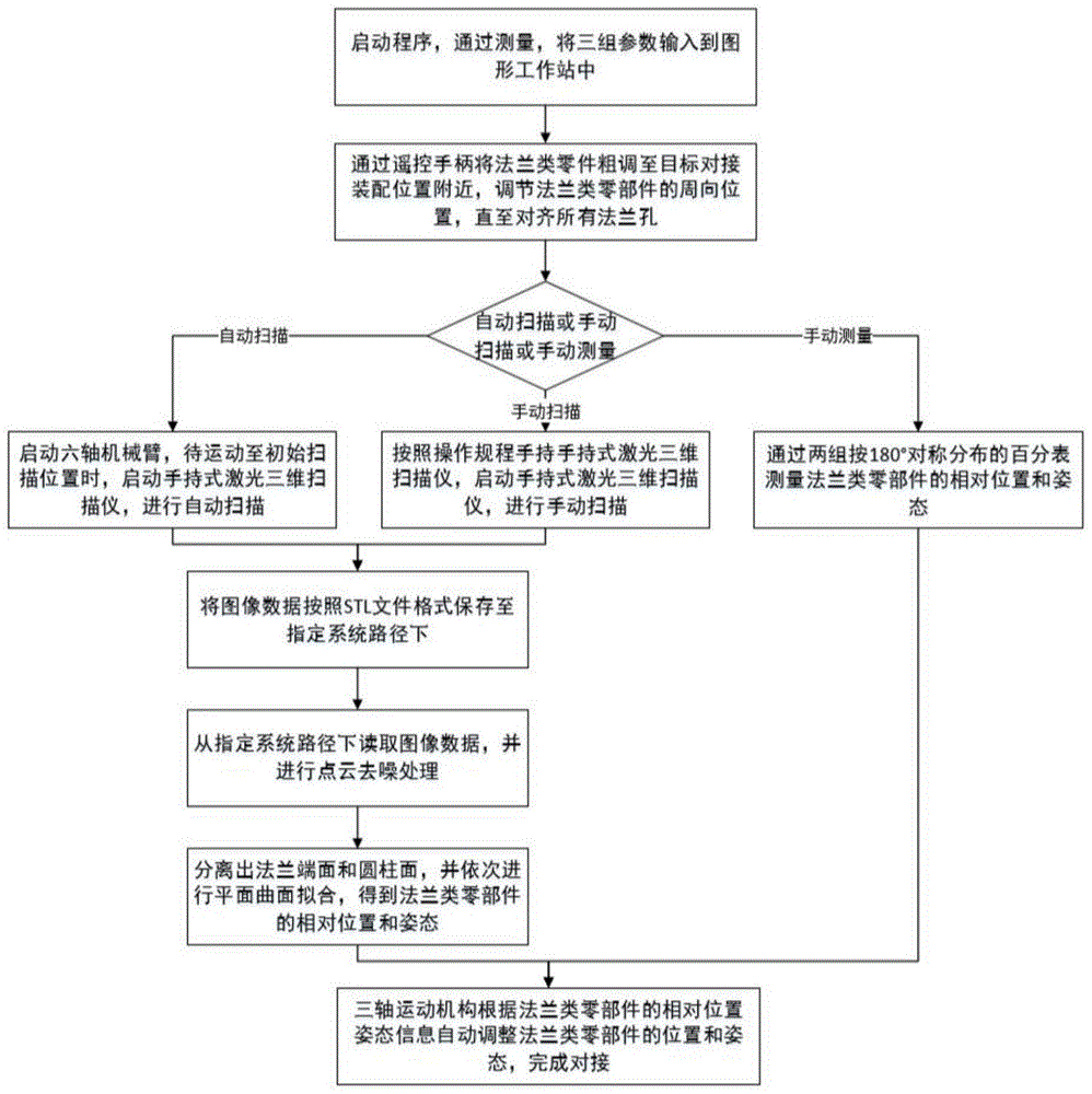
采用上述法兰零件智能对接系统进行法兰对接时,如图9所示,包括以下步骤:When using the above flange parts intelligent docking system for flange docking, as shown in Figure 9, the following steps are included:
1)根据装配环境和安装要求合理布局系统各部件,做好对接装配前的准备工作;1) According to the assembly environment and installation requirements, the components of the system should be reasonably arranged, and the preparations before the docking assembly should be done well;
2)插上电源,启动程序,通过测量提供三组参数,第一组参数为所述XY轴移动平台和所述电动缸的初始位移量;第二组参数为所述三轴运动机构33的底座距和高低差;第三组参数为所述法兰零件标准法兰所处位置、法兰直径、标准法兰轴径、对接法兰轴径以及标准法兰与对接法兰厚度之和,将这三组参数输入到所述图形工作站中;2) Plug in the power supply, start the program, and provide three sets of parameters through measurement, the first set of parameters is the initial displacement of the XY-axis moving platform and the electric cylinder; the second set of parameters is the three-axis motion mechanism 33. Base distance and height difference; the third group of parameters is the position of the standard flange of the flange part, flange diameter, standard flange shaft diameter, butt flange shaft diameter and the sum of the thickness of the standard flange and the butt flange, Input these three sets of parameters into the graphics workstation;
3)使用所述遥控手柄将所述法兰零件粗调至目标对接装配位置附近,调节所述法兰零件的周向位置,直至对齐所有法兰孔;3) Use the remote control handle to roughly adjust the flange parts to the vicinity of the target docking assembly position, and adjust the circumferential position of the flange parts until all flange holes are aligned;
4)通过主控制台上的主控界面启动六轴机械臂12,待所述六轴机械臂12运动至初始扫描位置时,启动所述手持式激光三维扫描仪11,所述六轴机械臂12按预定路径携带所述手持式激光三维扫描仪11对所述法兰零件进行扫描;也可由操作人员按照操作规程手持所述手持式激光三维扫描仪11对所述法兰零件进行扫描;也可由操作人员通过两组按180°对称分布的百分表4测量所述法兰零部件的相对位置和姿态;其中,前两种测量方式扫描完成之后,经由图像处理算法,可计算出所述法兰零件的空间相对位置和姿态;4) Start the six-axis robotic arm 12 through the main control interface on the main console, and when the six-axis robotic arm 12 moves to the initial scanning position, start the handheld laser 3D scanner 11, and the six-axis robotic arm 12 Carry the handheld laser 3D scanner 11 along a predetermined path to scan the flange parts; the operator can also hold the handheld laser 3D scanner 11 to scan the flange parts according to the operating procedures; The relative position and attitude of the flange parts can be measured by the operator through two sets of dial indicators 4 distributed symmetrically at 180°; among them, after the first two measurement methods are scanned, the image processing algorithm can be used to calculate the The relative position and attitude of flange parts in space;
5)通过所述主控制台上的主控界面发出自动对接指令,所述三轴运动机构33即可带动所述法兰零件运动至目标位置,完成对接工作;5) Issue an automatic docking command through the main control interface on the main console, and the three-axis motion mechanism 33 can drive the flange parts to move to the target position to complete the docking work;
6)安装好所述法兰零件紧固螺栓之后,使用所述遥控手柄控制所述三轴运动机构33脱离所述法兰零件,关闭程序,关闭电源。6) After installing the flange parts fastening bolts, use the remote control handle to control the three-axis motion mechanism 33 to separate from the flange parts, close the program, and turn off the power supply.
进一步的,基于运动学分析方法,针对所述六轴机械臂12的安装位置、所述手持式激光三维扫描仪11与所述法兰零件表面的距离、所述六轴机械臂12和所述手持式激光三维扫描仪11与所述法兰零件的防碰撞需求等约束条件,以关节角度、角速度为自变量,建立机械臂运动学方程,求解最优扫描路径,提高图像扫描效率。具体包括:Further, based on the kinematic analysis method, for the installation position of the six-axis robotic arm 12, the distance between the handheld laser 3D scanner 11 and the surface of the flange part, the six-axis robotic arm 12 and the The hand-held laser 3D scanner 11 and the flange parts' anti-collision requirements and other constraints, take the joint angle and angular velocity as independent variables, establish the kinematics equation of the manipulator, solve the optimal scanning path, and improve the image scanning efficiency. Specifically include:
(1)建立扫描路径规划目标函数PI(dj,βj):(1) Establish the scanning path planning objective function P I (d j ,β j ):

其中,
(2)确定约束条件fi1(dj,βj)~fi6(dj,βj):(2) Determine the constraints f i1 (d j ,β j )~f i6 (d j ,β j ):

其中,i=1,2;dj(djx,djy,djz)为机械臂末端位置,βj(βjx,βjy,βjz)为机械臂末端姿态,Dmax、Dmin分别为激光三维扫描仪最远有效扫描范围和最近有效扫描范围,t为法兰零件厚度,R、r分别为法兰零件的直径和轴径;且有:Among them, i=1,2; d j (d jx , d jy , d jz ) is the position of the end of the robot arm, β j (β jx , β jy , β jz ) is the posture of the end of the robot arm, D max and D min respectively is the farthest effective scanning range and the nearest effective scanning range of the laser 3D scanner, t is the thickness of the flange part, R and r are the diameter and shaft diameter of the flange part respectively; and there are:

其中,sl为激光三维扫描仪最远有效扫描范围下的成像边长;Among them, sl is the imaging side length under the farthest effective scanning range of the laser 3D scanner;
(3)根据约束条件,对扫描路径规划目标函数进行求解,得到激光三维扫描仪的扫描路径。(3) According to the constraints, the scanning path planning objective function is solved to obtain the scanning path of the laser 3D scanner.
进一步的,考虑到所述六轴机械臂12末端的运动空间以及所述六轴机械臂12和所述手持式激光三维扫描仪11与所述法兰零件的防碰撞需求,扫描得到的是所述法兰零件残缺的部分图像数据。Further, considering the movement space at the end of the six-axis manipulator 12 and the anti-collision requirements of the six-axis manipulator 12 and the hand-held laser 3D scanner 11 and the flange parts, the scanning results are all Part of the image data of the missing flange parts.
本发明提出的系统和方法适用于法兰零件,即两个平面在周边使用螺栓连接,同时封闭的连接零件,此外,也适用于带有法兰并可以进行法兰连接的零部件称为法兰类零部件。The system and method proposed in the present invention are applicable to flanged parts, that is, two planes are connected by bolts at the periphery and are closed at the same time. In addition, they are also applicable to parts with flanges and can be flanged. Blue parts.
本领域的技术人员容易理解,以上所述仅为本发明的较佳实施例而已,并不用以限制本发明,凡在本发明的精神和原则之内所作的任何修改、等同替换和改进等,均应包含在本发明的保护范围之内。Those skilled in the art can easily understand that the above are only preferred embodiments of the present invention, and are not intended to limit the present invention. Any modifications, equivalent replacements and improvements made within the spirit and principles of the present invention, etc., All should be included within the protection scope of the present invention.
Claims (7)


Priority Applications (1)
| Application Number | Priority Date | Filing Date | Title |
|---|---|---|---|
| CN202110127376.9A CN112828552B (en) | 2021-01-29 | 2021-01-29 | Intelligent butt joint method and system for flange parts |
Applications Claiming Priority (1)
| Application Number | Priority Date | Filing Date | Title |
|---|---|---|---|
| CN202110127376.9A CN112828552B (en) | 2021-01-29 | 2021-01-29 | Intelligent butt joint method and system for flange parts |
Publications (2)
| Publication Number | Publication Date |
|---|---|
| CN112828552A CN112828552A (en) | 2021-05-25 |
| CN112828552B true CN112828552B (en) | 2022-05-20 |
Family
ID=75931041
Family Applications (1)
| Application Number | Title | Priority Date | Filing Date |
|---|---|---|---|
| CN202110127376.9A Active CN112828552B (en) | 2021-01-29 | 2021-01-29 | Intelligent butt joint method and system for flange parts |
Country Status (1)
| Country | Link |
|---|---|
| CN (1) | CN112828552B (en) |
Families Citing this family (10)
| Publication number | Priority date | Publication date | Assignee | Title |
|---|---|---|---|---|
| CN114393382B (en) * | 2021-12-22 | 2024-05-14 | 上海智能制造功能平台有限公司 | A vision-guided assembly docking device and method |
| CN114850855B (en) * | 2022-05-09 | 2023-05-26 | 西北工业大学 | Automatic leveling device and method for cylinder body of actuator cylinder |
| CN116071353B (en) * | 2023-03-06 | 2023-09-05 | 成都盛锴科技有限公司 | Bolt assembly detection method and system |
| CN117150676B (en) * | 2023-09-06 | 2024-08-02 | 华中科技大学 | Manufacturing method, system, equipment and medium for point cloud data set of ship shafting flange |
| CN118418073B (en) * | 2024-07-04 | 2024-09-06 | 湖南长高电气有限公司 | Multi-station automatic assembly control method for GIS equipment |
| CN120002359B (en) * | 2025-03-31 | 2025-11-04 | 华中科技大学 | Method for assembling high-locking bolt in aircraft |
| CN120740430A (en) * | 2025-06-20 | 2025-10-03 | 哈尔滨工业大学 | Measurement and adjustment method and system for large spherical shell flange assembly |
| CN120480931B (en) * | 2025-07-18 | 2025-09-16 | 南京航空航天大学 | Automatic fluid loading and unloading arm dynamic flange butt joint method based on image vision servo |
| CN120985674B (en) * | 2025-10-22 | 2026-01-23 | 国网上海市电力公司 | A method for pipe flange connection based on multi-sensor collaboration and a storage medium |
| CN121546479A (en) * | 2026-01-19 | 2026-02-17 | 国网上海市电力公司 | A machine vision-based method and system for assisted docking of GIL pipes |
Citations (9)
| Publication number | Priority date | Publication date | Assignee | Title |
|---|---|---|---|---|
| CN201053864Y (en) * | 2006-11-04 | 2008-04-30 | 大连海事大学 | Intelligent holographic three-dimensional laser measuring device |
| CN106903663A (en) * | 2017-03-03 | 2017-06-30 | 航天材料及工艺研究所 | A kind of positioning and marking method, the apparatus and system of the built-in part of revolving shell |
| CN107138944A (en) * | 2017-05-18 | 2017-09-08 | 哈尔滨工业大学 | The two workpiece automatic aligning methods based on spatial point error correction |
| CN108274231A (en) * | 2017-12-05 | 2018-07-13 | 上海航天精密机械研究所 | Bay section class part automatic butt jointing device and control method |
| CN108931194A (en) * | 2018-07-10 | 2018-12-04 | 苏州艾弗伦智能技术有限公司 | A kind of intelligent robot 3D precision measurement system |
| CN109373898A (en) * | 2018-11-27 | 2019-02-22 | 华中科技大学 | A system and method for pose estimation of complex parts based on 3D measurement point cloud |
| CN110268221A (en) * | 2016-11-29 | 2019-09-20 | 明电舍公司 | Wire rope measuring device and wire rope measuring method |
| CN111638680A (en) * | 2020-06-15 | 2020-09-08 | 大连誉洋工业智能有限公司 | A robot-based grinding path planning method for circular structures of castings |
| CN112082493A (en) * | 2020-09-03 | 2020-12-15 | 武汉工程大学 | Visual measurement method for inner radius of pipeline flange based on binocular imaging |
Family Cites Families (1)
| Publication number | Priority date | Publication date | Assignee | Title |
|---|---|---|---|---|
| CN108942942B (en) * | 2018-08-16 | 2020-01-07 | 居鹤华 | Multi-axis robot inverse kinematics modeling and resolving method based on axis invariants |
-
2021
- 2021-01-29 CN CN202110127376.9A patent/CN112828552B/en active Active
Patent Citations (9)
| Publication number | Priority date | Publication date | Assignee | Title |
|---|---|---|---|---|
| CN201053864Y (en) * | 2006-11-04 | 2008-04-30 | 大连海事大学 | Intelligent holographic three-dimensional laser measuring device |
| CN110268221A (en) * | 2016-11-29 | 2019-09-20 | 明电舍公司 | Wire rope measuring device and wire rope measuring method |
| CN106903663A (en) * | 2017-03-03 | 2017-06-30 | 航天材料及工艺研究所 | A kind of positioning and marking method, the apparatus and system of the built-in part of revolving shell |
| CN107138944A (en) * | 2017-05-18 | 2017-09-08 | 哈尔滨工业大学 | The two workpiece automatic aligning methods based on spatial point error correction |
| CN108274231A (en) * | 2017-12-05 | 2018-07-13 | 上海航天精密机械研究所 | Bay section class part automatic butt jointing device and control method |
| CN108931194A (en) * | 2018-07-10 | 2018-12-04 | 苏州艾弗伦智能技术有限公司 | A kind of intelligent robot 3D precision measurement system |
| CN109373898A (en) * | 2018-11-27 | 2019-02-22 | 华中科技大学 | A system and method for pose estimation of complex parts based on 3D measurement point cloud |
| CN111638680A (en) * | 2020-06-15 | 2020-09-08 | 大连誉洋工业智能有限公司 | A robot-based grinding path planning method for circular structures of castings |
| CN112082493A (en) * | 2020-09-03 | 2020-12-15 | 武汉工程大学 | Visual measurement method for inner radius of pipeline flange based on binocular imaging |
Non-Patent Citations (3)
| Title |
|---|
| SCARA四轴机器人控制系统综述;杨明等;《电气传动》;20200120(第01期);全文 * |
| 基于DE的时间最优6-DOF机械臂轨迹规划算法;王学琨等;《计算机仿真》;20150815(第08期);全文 * |
| 面向智能装配的残缺图像轴系位姿测量算法;雷盼等;《2019全国仿真技术学术会议论文集》;20190831;第225-228页 * |
Also Published As
| Publication number | Publication date |
|---|---|
| CN112828552A (en) | 2021-05-25 |
Similar Documents
| Publication | Publication Date | Title |
|---|---|---|
| CN112828552B (en) | Intelligent butt joint method and system for flange parts | |
| CN110370286B (en) | Recognition method of fixed-axis motion rigid body space position based on industrial robot and monocular camera | |
| US11044011B2 (en) | Automated scanning systems for non-destructive inspection of curved cylinder-like workpieces | |
| US11555693B2 (en) | Measurement of surface profiles using unmanned aerial vehicles | |
| CN112010024B (en) | Automatic container grabbing method and system based on laser and vision fusion detection | |
| CN112833786A (en) | A cabin position and attitude measurement and alignment system, control method and application | |
| CN109794963B (en) | A fast positioning method of robots for curved surface components | |
| CA2948485C (en) | Methods and systems for wing-to-body joining | |
| CN109764805B (en) | Mechanical arm positioning device and method based on laser scanning | |
| US11635408B2 (en) | Method for tracking location of two-dimensional non-destructive inspection scanner on target object using scanned structural features | |
| CN110919654A (en) | Automatic butt joint system of arm based on visual servo | |
| JP2004508954A (en) | Positioning device and system | |
| WO2023185550A1 (en) | Visual measurement guiding device, method and system for cylinder nested assembly centering | |
| CN113246142B (en) | Measuring path planning method based on laser guidance | |
| Tian et al. | A technology framework for robotic profiling of blade edges based on model reconstruction and trajectory replanning | |
| CN109773589B (en) | Method, device and equipment for online measurement and machining guidance of workpiece surface | |
| CN114720476A (en) | Intelligent detection and polishing method for defects of automobile body paint surface | |
| US12374123B2 (en) | Enhanced vehicle navigation using non-destructive inspection one-dimensional sensor arrays | |
| CN111801195A (en) | Automatic grinding system | |
| CN111745623A (en) | A system and method for detecting and compensating the end pose error of a five-degree-of-freedom hybrid robot | |
| CN118123860B (en) | An assembly robot and assembly method for special-shaped curved surface accessories in a helicopter | |
| CN114998422A (en) | A High Precision and Fast 3D Positioning System Based on Error Compensation Model | |
| CN110961583B (en) | Ladle positioning device adopting laser scanning and using method thereof | |
| CN110081821A (en) | Intelligent high-speed rail white body assembling quality detection device and its method | |
| EP3745118A1 (en) | Optical imaging and scanning of holes |
Legal Events
| Date | Code | Title | Description |
|---|---|---|---|
| PB01 | Publication | ||
| PB01 | Publication | ||
| SE01 | Entry into force of request for substantive examination | ||
| SE01 | Entry into force of request for substantive examination | ||
| GR01 | Patent grant | ||
| GR01 | Patent grant |