CN112828158B - Production die for lead frame convenient to replace and replacement method thereof - Google Patents
Production die for lead frame convenient to replace and replacement method thereof Download PDFInfo
- Publication number
- CN112828158B CN112828158B CN202110012509.8A CN202110012509A CN112828158B CN 112828158 B CN112828158 B CN 112828158B CN 202110012509 A CN202110012509 A CN 202110012509A CN 112828158 B CN112828158 B CN 112828158B
- Authority
- CN
- China
- Prior art keywords
- guide
- mounting panel
- limiting
- die holder
- positioning
- Prior art date
- Legal status (The legal status is an assumption and is not a legal conclusion. Google has not performed a legal analysis and makes no representation as to the accuracy of the status listed.)
- Active
Links
Images


Classifications
-
- B—PERFORMING OPERATIONS; TRANSPORTING
- B21—MECHANICAL METAL-WORKING WITHOUT ESSENTIALLY REMOVING MATERIAL; PUNCHING METAL
- B21D—WORKING OR PROCESSING OF SHEET METAL OR METAL TUBES, RODS OR PROFILES WITHOUT ESSENTIALLY REMOVING MATERIAL; PUNCHING METAL
- B21D37/00—Tools as parts of machines covered by this subclass
- B21D37/10—Die sets; Pillar guides
-
- B—PERFORMING OPERATIONS; TRANSPORTING
- B21—MECHANICAL METAL-WORKING WITHOUT ESSENTIALLY REMOVING MATERIAL; PUNCHING METAL
- B21D—WORKING OR PROCESSING OF SHEET METAL OR METAL TUBES, RODS OR PROFILES WITHOUT ESSENTIALLY REMOVING MATERIAL; PUNCHING METAL
- B21D22/00—Shaping without cutting, by stamping, spinning, or deep-drawing
- B21D22/02—Stamping using rigid devices or tools
-
- B—PERFORMING OPERATIONS; TRANSPORTING
- B21—MECHANICAL METAL-WORKING WITHOUT ESSENTIALLY REMOVING MATERIAL; PUNCHING METAL
- B21D—WORKING OR PROCESSING OF SHEET METAL OR METAL TUBES, RODS OR PROFILES WITHOUT ESSENTIALLY REMOVING MATERIAL; PUNCHING METAL
- B21D37/00—Tools as parts of machines covered by this subclass
- B21D37/10—Die sets; Pillar guides
- B21D37/12—Particular guiding equipment, e.g. pliers; Special arrangements for interconnection or cooperation of dies
-
- B—PERFORMING OPERATIONS; TRANSPORTING
- B21—MECHANICAL METAL-WORKING WITHOUT ESSENTIALLY REMOVING MATERIAL; PUNCHING METAL
- B21D—WORKING OR PROCESSING OF SHEET METAL OR METAL TUBES, RODS OR PROFILES WITHOUT ESSENTIALLY REMOVING MATERIAL; PUNCHING METAL
- B21D37/00—Tools as parts of machines covered by this subclass
- B21D37/14—Particular arrangements for handling and holding in place complete dies
-
- B—PERFORMING OPERATIONS; TRANSPORTING
- B21—MECHANICAL METAL-WORKING WITHOUT ESSENTIALLY REMOVING MATERIAL; PUNCHING METAL
- B21D—WORKING OR PROCESSING OF SHEET METAL OR METAL TUBES, RODS OR PROFILES WITHOUT ESSENTIALLY REMOVING MATERIAL; PUNCHING METAL
- B21D37/00—Tools as parts of machines covered by this subclass
- B21D37/16—Heating or cooling
Abstract
The invention discloses a production die for a lead frame convenient to replace and a replacement method thereof, and relates to the technical field of dies. Bearing mounting holes are formed in the two sides of the mounting panel body, a bearing mounting seat is arranged in each bearing mounting hole, a bidirectional threaded rod is arranged in the mounting panel body in a rotating mode through the bearing mounting seats, transverse limiting grooves are formed in the positions, located in the bearing mounting holes, of the surface of the mounting panel body, side guide grooves are formed in the two sides of the inner wall of each transverse limiting groove, movable limiting blocks are symmetrically arranged in the two sides, located in the transverse limiting grooves, of the inner wall of each bidirectional threaded rod, guide limiting blocks are fixedly arranged on the two sides of the lower end of each movable limiting block, fastening nuts are fixedly arranged on the end face of the upper end of each movable limiting block, an upper limiting cover plate is arranged on the upper end of each movable limiting block through the fastening nuts, and the problem that replacement work cannot be well conducted is solved, so that replacement is inconvenient, replacement time is overlong, and production and machining time are delayed is solved.
Description
Technical Field
The invention relates to the technical field of dies, in particular to a production die for a lead frame convenient to replace and a replacement method thereof.
Background
The mould (m, muu) is used for producing various moulds and tools for injection moulding, blow moulding, extrusion, die casting or forging, smelting, stamping and other methods to obtain the required products in industrial production. In short, a mold is a tool used to make a molded article, which is made up of various parts, with different molds being made up of different parts. The processing of the appearance of the article is realized mainly by changing the physical state of the formed material. The term "industrial mother" is used.
The blank is made into a tool with a specific shape and size under the action of external force. The method is widely used for blanking, die forging, cold heading, extrusion, powder metallurgy part pressing, pressure casting and the molding processing of compression molding or injection molding of engineering plastics, rubber, ceramics and other products. The die has a specific contour or cavity shape, and the blank can be separated (blanked) according to the contour shape by using the contour shape with the cutting edge. The blank can obtain a corresponding three-dimensional shape by using the shape of the inner cavity. The mold generally comprises a movable mold and a fixed mold (or a male mold and a female mold), which can be separated and combined. And taking out the workpiece when the workpiece is separated, and injecting the blank into the die cavity for forming when the workpiece is closed. The die is a precise tool, has a complex shape, bears the expansion force of a blank, has higher requirements on structural strength, rigidity, surface hardness, surface roughness and machining precision, and is one of important marks of the mechanical manufacturing level.
The traditional production mold for the lead frame has certain defects when in use, and can not be well replaced, so that the replacement is inconvenient, the replacement time is too long, and the production and processing time is delayed.
Disclosure of Invention
Aiming at the defects of the prior art, the invention provides a production die for a lead frame and a replacement method thereof, which are convenient to replace, and solves the problems that the lead frame cannot be replaced well, the replacement is inconvenient, the replacement time is too long, and the production and processing time is delayed.
In order to achieve the above purpose, the invention is realized by the following technical scheme: the utility model provides a production mould for lead frame convenient to change, includes installation panel, upper die base, guide pillar, die holder, lower installation panel, guiding hole and location installation panel, the installation panel includes installation panel main part down, the bearing mounting hole has all been seted up to the inside both sides of installation panel main part, every the inside of bearing mounting hole is provided with the bearing mount pad, the inside of installation panel main part rotates through the bearing mount pad and is provided with two-way threaded rod, the horizontal limit groove has been seted up to the on-surface that lies in bearing mounting hole department of installation panel main part, lateral limit groove has been seted up to the inner wall both sides of horizontal limit groove, the inside symmetry that lies in horizontal limit groove on the surface of two-way threaded rod is provided with the removal limiting block, the fixed guiding limiting block that is provided with in lower extreme both sides of removal limiting block, the fixed fastening nut that is provided with on the upper end terminal surface of removal limiting block, be provided with the restriction apron through fastening nut on the surface with the screw thread mode, and restriction double-screw bolt sets up the top at the upper end of upper end, link to each other through the fixed drive shaft coupling between the drive end of drive motor and the limit shaft.
As a further scheme of the invention: the installation panel comprises an installation panel body, wherein a guide groove is formed in one end surface of the installation panel body, a longitudinal limiting plate is arranged in the guide groove formed in the surface of the installation panel body in a sliding mode, positioning installation rods are fixedly arranged at two ends of the longitudinal limiting plate, guide limiting grooves are formed in two side surfaces of the guide groove, and the guide limiting grooves are matched with the positioning installation rods.
As a further scheme of the invention: the installation panel is characterized in that a longitudinal guide groove is formed in the end face, deviating from the guide groove, of the installation panel body, guide connecting columns are fixedly arranged on two sides of the interior of the longitudinal guide groove, longitudinal limiting blocks are arranged on the surfaces of the guide connecting columns in a sliding mode, and limiting cover plates are arranged on the upper side end faces of the longitudinal limiting blocks.
As a further scheme of the invention: the installation panel comprises an installation panel body, and is characterized in that a plurality of installation grooves are formed in the surface of the installation panel body, a rotating shaft is fixedly arranged at one end of the inside of each installation groove, an inclined top block is arranged in the inside of each installation groove in a rotating mode through the rotating shaft, and a lower spring is connected between the lower side of each inclined top block and the upper end face of each installation groove.
As a further scheme of the invention: the upper die holder is installed in the downside of last installation panel, the guide pillar sets up in the four corners department of upper die holder, the four corners department at the die holder is seted up to the guiding hole, and looks adaptation between guide pillar and the guiding hole, location installation panel sets up the bottom at the die holder, location installation panel includes location installation panel main part, the fastening connecting hole has been seted up on the surface of location installation panel main part, the die holder passes through the fastening connecting hole to be fixed in location installation panel main part.
As a further scheme of the invention: the upper mounting panel comprises an upper mounting panel main body, a matrix frame is fixedly arranged on the surface of the lower side of the upper mounting panel main body, hydraulic cylinders are fixedly arranged at four corners of the matrix frame, guide rails are arranged at the moving ends of the hydraulic cylinders, and cooling liquid spray heads are slidably arranged on the surfaces of the guide rails.
As a further scheme of the invention: the guide limiting block is matched with the side guide groove, the longitudinal limiting plate is matched with the guide groove, and a hole groove matched with the inclined jacking block is formed in the bottom surface of the positioning and mounting panel main body.
A method for replacing a production die for a lead frame convenient to replace comprises the following steps:
step S1: cleaning and debugging the whole die composed of the upper die holder, the guide post, the lower die holder, the guide hole and the positioning installation panel, and closing the die before installation, and installing the die composed of the upper die holder, the guide post, the lower die holder, the guide hole and the positioning installation panel on a punching bed body composed of the upper installation panel and the lower installation panel after debugging and closing the die;
step S2: the lower mounting panel on the punch press integrally extends along with the driving part on the lower side, the die composed of the upper die holder, the guide post, the lower die holder, the guide hole and the positioning mounting panel is lifted onto the lower mounting panel under the action of the lifting crane, the die composed of the upper die holder, the guide post, the lower die holder, the guide hole and the positioning mounting panel is integrally pushed between the upper limiting cover plates on the lower mounting panel, the front end of the die composed of the upper die holder, the guide post, the lower die holder, the guide hole and the positioning mounting panel is contacted with the longitudinal limiting block on the mounting panel main body, the die continues to move forwards, the longitudinal limiting block moves along the direction in the longitudinal guide groove, the spring piece connected with the longitudinal limiting block is lengthened until the longitudinal limiting block abuts against the side wall surface of the longitudinal guide groove, and the inclined top block is aligned with the hole groove on the positioning mounting panel under the pushing of the die;
step S3: the die formed by the upper die holder, the guide post, the lower die holder, the guide hole and the positioning installation panel stops at a longitudinal limiting block, then, the movement limiting blocks at the two sides start to operate, the driving motor starts to drive the bidirectional threaded rod to rotate, the rotation of the bidirectional threaded rod drives the movement limiting block to displace along the direction of the guide limiting block, the two movement limiting blocks on the bidirectional threaded rod relatively displace, the two sides of the positioning installation panel are clamped and limited, the upper limiting cover plate at the upper side of the movement limiting block is limited by a fastening nut, and the movement limiting block is fastened by a limiting stud;
step S4: the die composed of the upper die base, the guide post, the lower die base, the guide hole and the positioning installation panel is fastened under the action of the movement limiting blocks at the two sides, after fastening, the longitudinal limiting plate is slidably installed in the guide groove, the longitudinal limiting plate is fixed through the positioning installation rod, and the side edge of the longitudinal limiting plate is contacted with the side edge of the die composed of the upper die base, the guide post, the lower die base, the guide hole and the positioning installation panel, so that the fixing is completed.
Advantageous effects
The invention provides a production die for a lead frame, which is convenient to replace, and a replacement method thereof. Compared with the prior art, the method has the following beneficial effects:
1. the utility model provides a production mould and change method for lead frame convenient to change, both sides through the installation panel main part are inside to be seted up the bearing mounting hole, the inside of every bearing mounting hole is provided with the bearing mount pad, the inside of installation panel main part is provided with two-way threaded rod through bearing mount pad rotation, transverse limiting groove has been seted up to the surface that lies in bearing mounting hole department of installation panel main part, lateral side guide groove has been seted up to the inner wall both sides of transverse limiting groove, the surface that lies in transverse limiting groove on two-way threaded rod is provided with the removal limiting block symmetrically, the lower extreme both sides of removal limiting block are fixed to be provided with the direction limiting block, the upper end face of removal limiting block is fixed and is provided with fastening nut, be provided with the upper limit apron on the upper end of removal limiting block through fastening nut with the screw thread mode, and the limit stud sets up the top at the upper limit apron, be fixedly connected through the shaft coupling between the drive end of two-way one end and driving motor, it has been solved and can not fine change work, this just results in inconvenient, change time overlength, the problem of production process time is delayed.
2. A production die for a lead frame convenient to replace and a replacement method thereof are provided, wherein a guide groove is formed in one end surface of a mounting panel main body, longitudinal limiting plates are arranged in the guide groove formed in the surface of the mounting panel main body in a sliding mode, positioning mounting rods are fixedly arranged at two ends of each longitudinal limiting plate, guide limiting grooves are formed in two side surfaces of the guide groove, the guide limiting grooves are matched with the positioning mounting rods, longitudinal guide grooves are formed in end surfaces, deviating from the guide grooves, of the mounting panel main body, guide connecting columns are fixedly arranged on two inner sides of the longitudinal guide grooves, longitudinal limiting blocks are arranged on the surfaces of the guide connecting columns in a sliding mode, and limiting cover plates are arranged on the upper side end surfaces of the longitudinal limiting blocks, so that the quick replacement assembly of the die with certain thickness is met.
3. The production die for the lead frame convenient to replace comprises an upper mounting panel body, wherein a matrix frame is fixedly arranged on the surface of the lower side of the upper mounting panel body, hydraulic cylinders are fixedly arranged at four corners of the matrix frame, guide rails are arranged at the moving ends of the hydraulic cylinders, and cooling liquid spray heads are arranged on the surfaces of the guide rails in a sliding manner, so that the surfaces of the dies can be cleaned and cooled, and the assembly precision is improved.
Drawings
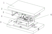
FIG. 1 is a schematic diagram of the structure of the present invention;
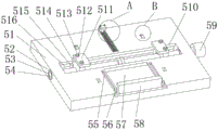
FIG. 2 is a schematic view of the rear side structure of the present invention;
FIG. 3 is a schematic view of a positioning mounting panel structure according to the present invention;
FIG. 4 is a schematic view of a positioning mounting panel structure according to the present invention;
FIG. 5 is a schematic view of the structure of the upper mounting panel of the present invention;
FIG. 6 is an enlarged view of the structure shown at A in FIG. 4;
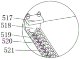
fig. 7 is a schematic diagram of the structure at B in fig. 4.
In the figure: 1. a top mounting panel; 11. an upper mounting panel body; 12. a base frame; 13. a hydraulic cylinder; 14. a guide rail; 15. a cooling liquid spray head; 2. an upper die holder; 3. a guide post; 4. a lower die holder; 5. a lower mounting panel; 51. mounting a panel main body; 52. bearing mounting holes; 53. a bearing mounting seat; 54. a two-way threaded rod; 55. a guide restricting groove; 56. positioning the mounting rod; 57. a guide groove; 58. a longitudinal limiting plate; 59. a driving motor; 510. a lateral limiting groove; 511. an upper limiting cover plate; 512. limiting the stud; 513. a fastening nut; 514. a movement limiting block; 515. a guide restricting block; 516. a side guide groove; 517. a limiting cover plate; 518. a longitudinal limiting block; 519. a longitudinal guide groove; 520. a guide connecting column; 521. a spring member; 522. an inclined top block; 523. a rotating shaft; 524. a mounting groove; 525. a lower spring; 6. a guide hole; 7. positioning and installing a panel; 71. positioning and mounting a panel main body; 72. fastening the connecting hole.
Detailed Description
The following description of the embodiments of the present invention will be made clearly and completely with reference to the accompanying drawings, in which it is apparent that the embodiments described are only some embodiments of the present invention, but not all embodiments. All other embodiments, which can be made by those skilled in the art based on the embodiments of the invention without making any inventive effort, are intended to be within the scope of the invention.
Referring to fig. 1-7, the present invention provides a technical solution: the production die for the lead frame convenient to replace comprises an upper mounting panel 1, an upper die holder 2, guide posts 3, a lower die holder 4, a lower mounting panel 5, guide holes 6 and a positioning mounting panel 7, wherein the lower mounting panel 5 comprises a mounting panel main body 51, bearing mounting holes 52 are formed in two sides of the mounting panel main body 51, a bearing mounting seat 53 is arranged in each bearing mounting hole 52, a bidirectional threaded rod 54 is rotatably arranged in the mounting panel main body 51 through the bearing mounting seat 53, a transverse limiting groove 510 is formed in the surface of the mounting panel main body 51 and positioned at the bearing mounting hole 52, side guide grooves 516 are formed in two sides of the inner wall of the transverse limiting groove 510, movable limiting blocks 514 are symmetrically arranged in the transverse limiting groove 510 on the surface of the bidirectional threaded rod 54, guide limiting blocks 515 are fixedly arranged on two sides of the lower end of the movement limiting block 514, a fastening nut 513 is fixedly arranged on the end face of the upper end of the movement limiting block 514, an upper limiting cover plate 511 is arranged on the upper end of the movement limiting block 514 through the fastening nut 513, limiting studs 512 are arranged on the surface of the fastening nut 513 in a threaded mode, the limiting studs 512 are arranged above the upper limiting cover plate 511, one end of a bidirectional threaded rod 54 is fixedly connected with the driving end of a driving motor 59 through a coupler, a guide groove 57 is formed on one end surface of the mounting panel main body 51, a longitudinal limiting plate 58 is arranged in the guide groove 57 formed on the surface of the mounting panel main body 51 in a sliding mode, positioning mounting rods 56 are fixedly arranged on two ends of the longitudinal limiting plate 58, guide limiting grooves 55 are formed on two side surfaces of the guide groove 57, the guide limiting groove 55 is matched with the positioning mounting rod 56, a longitudinal guide groove 519 is formed on the end face, away from the guide groove 57, of the mounting panel main body 51, guide connecting columns 520 are fixedly arranged on two sides of the inner portion of the longitudinal guide groove 519, longitudinal limiting blocks 518 are slidably arranged on the surface of the guide connecting columns 520, limiting cover plates 517 are arranged on the upper end face of the longitudinal limiting blocks 518, a plurality of mounting grooves 524 are formed on the surface of the mounting panel main body 51, rotating shafts 523 are fixedly arranged at one end of the inner portion of each mounting groove 524, inclined jacking blocks 522 are rotatably arranged in the mounting grooves 524 through the rotating shafts 523, lower springs 525 are connected between the lower sides of the inclined jacking blocks 522 and the upper end faces of the mounting grooves, the upper die holders 2 are mounted on the lower sides of the upper mounting panel 1, guide columns 3 are arranged at four corners of the upper die holders 2, the guide holes 6 are formed at four corners of the lower die holder 4, the guide posts 3 are matched with the guide holes 6, the positioning and mounting panel 7 is arranged at the bottom of the lower die holder 4, the positioning and mounting panel 7 comprises a positioning and mounting panel main body 71, fastening connection holes 72 are formed on the surface of the positioning and mounting panel main body 71, the lower die holder 4 is fixed on the positioning and mounting panel main body 71 through the fastening connection holes 72, the upper mounting panel 1 comprises an upper mounting panel main body 11, a base frame 12 is fixedly arranged on the lower side surface of the upper mounting panel main body 11, hydraulic cylinders 13 are fixedly arranged at four corners of the base frame 12, guide rails 14 are arranged on the moving ends of the hydraulic cylinders 13, cooling liquid spray heads 15 are slidably arranged on the surfaces of the guide rails 14, the guide limiting blocks 515 are matched with the side guide grooves 516, the longitudinal limiting plate 58 is matched with the guide groove 57, and a hole groove matched with the inclined top block 522 is formed in the bottom surface of the positioning and mounting panel main body 71.
A method for replacing a production die for a lead frame convenient to replace comprises the following steps:
step S1: cleaning and debugging the whole die composed of the upper die holder 2, the guide post 3, the lower die holder 4, the guide hole 6 and the positioning and mounting panel 7, and closing the die before mounting, and mounting the die composed of the upper die holder 2, the guide post 3, the lower die holder 4, the guide hole 6 and the positioning and mounting panel 7 on a punching machine body composed of the upper mounting panel 1 and the lower mounting panel 5 after debugging and closing the die;
step S2: the lower mounting panel 5 on the punching machine integrally extends along with the lower driving part, the die composed of the upper die holder 2, the guide post 3, the lower die holder 4, the guide hole 6 and the positioning mounting panel 7 is lifted onto the lower mounting panel 5 under the action of the lifting crane, the die composed of the upper die holder 2, the guide post 3, the lower die holder 4, the guide hole 6 and the positioning mounting panel 7 is integrally pushed between the upper limiting cover plates 511 on the lower mounting panel 5, the front end of the die composed of the upper die holder 2, the guide post 3, the lower die holder 4, the guide hole 6 and the positioning mounting panel 7 is contacted with the longitudinal limiting block 518 on the mounting panel main body 51, the die continues to move forwards, the longitudinal limiting block 518 moves along the direction in the longitudinal guiding groove 519, and the spring element 521 connected with the longitudinal limiting block 518 is stretched until the longitudinal limiting block 518 abuts against the side wall surface of the longitudinal guiding groove 519, and the inclined top block 522 is aligned and limited with the hole groove on the positioning mounting panel 7 under the pushing of the die;
step S3: the die composed of the upper die holder 2, the guide post 3, the lower die holder 4, the guide hole 6 and the positioning and mounting panel 7 is stopped at a longitudinal limiting block 518, then, the movement limiting blocks 514 on the two sides start to operate, the driving motor 59 is started to drive the bidirectional threaded rod 54 to rotate, the rotation of the bidirectional threaded rod 54 drives the movement limiting blocks 514 to displace along the direction of the guide limiting blocks 515, the two movement limiting blocks 514 on the bidirectional threaded rod 54 relatively displace, the two sides of the positioning and mounting panel 7 are clamped and limited, the upper limiting cover plate 511 on the upper side of the movement limiting blocks 514 is limited by the fastening nuts 513, and the fastening is performed by the limiting studs 512;
step S4: the die composed of the upper die holder 2, the guide post 3, the lower die holder 4, the guide hole 6 and the positioning and mounting panel 7 is fastened under the action of the movement limiting blocks 514 on the two sides, after fastening, the longitudinal limiting plate 58 is slidably mounted in the guide groove 57, the longitudinal limiting plate 58 is fixed through the positioning and mounting rod 56, and the side edge of the longitudinal limiting plate 58 is contacted with the side edge of the die composed of the upper die holder 2, the guide post 3, the lower die holder 4, the guide hole 6 and the positioning and mounting panel 7, so that the fixing is completed.
When the invention is used, the whole die composed of the upper die holder 2, the guide post 3, the lower die holder 4, the guide hole 6 and the positioning mounting panel 7 is cleaned and debugged, and the die is assembled before mounting, after the die assembly is debugged and matched, the die composed of the upper die holder 2, the guide post 3, the lower die holder 4, the guide hole 6 and the positioning mounting panel 7 is mounted on a punching machine body composed of the upper mounting panel 1 and the lower mounting panel 5, the whole die composed of the upper die holder 2, the guide post 3, the lower die holder 4, the guide hole 6 and the positioning mounting panel 7 is lifted onto the lower mounting panel 5 under the action of lifting crane, the whole die composed of the upper die holder 2, the guide post 3, the lower die holder 4, the guide hole 6 and the positioning mounting panel 7 is pushed between the upper limiting cover plates 511 on the lower mounting panel 5, the front end of the die composed of the upper die holder 2, the guide post 3, the lower die holder 4, the guide hole 6 and the positioning mounting panel 7 is contacted with the longitudinal limiting block 518 on the mounting panel main body 51, the die continues to move forwards, the longitudinal limiting block 518 moves along the direction in the longitudinal guide groove 519, the spring element 521 connected with the longitudinal limiting block 518 is lengthened until the longitudinal limiting block 518 abuts against the side wall surface of the longitudinal guide groove 519, the inclined top block 522 is aligned and limited with the hole groove on the positioning mounting panel 7 under the pushing of the die, the die composed of the upper die holder 2, the guide post 3, the lower die holder 4, the guide hole 6 and the positioning mounting panel 7 stops at the longitudinal limiting block 518, then, the movement limiting blocks 514 on both sides start to operate, the driving motor 59 starts to drive the bidirectional threaded rod 54 to rotate, the rotation of the bidirectional threaded rod 54 drives the movement limiting block 514 to displace along the direction of the guide limiting block 515, and the two movement limiting blocks 514 on the bidirectional threaded rod 54 relatively displace to clamp and limit two sides of the positioning installation panel 7, and the upper limiting cover plate 511 on the upper side of the movement limiting block 514 is limited by the fastening nut 513, and the upper die holder 2, the guide post 3, the lower die holder 4, the guide hole 6 and the positioning installation panel 7 are fastened under the action of the movement limiting blocks 514 on the two sides, after fastening, the longitudinal limiting plate 58 is slidably installed in the guide groove 57, the longitudinal limiting plate 58 is fixed through the positioning installation rod 56, and the side edges of the longitudinal limiting plate 58 are contacted with the side edges of the die consisting of the upper die holder 2, the guide post 3, the lower die holder 4, the guide hole 6 and the positioning installation panel 7, so that the fixing is completed.
In the description of the present invention, it should be understood that the terms "upper," "lower," "left," "right," and the like indicate an orientation or a positional relationship based on that shown in the drawings, and are merely for convenience of description and for simplifying the description, and do not indicate or imply that the apparatus or element in question must have a specific orientation, as well as a specific orientation configuration and operation, and thus should not be construed as limiting the present invention. Furthermore, the terms "first," "second," and the like, are used for descriptive purposes only and are not to be construed as indicating or implying a relative importance or implicitly indicating the number of technical features indicated. Thus, a feature defining "a first" or "a second" may explicitly or implicitly include one or more such feature. In the description of the present invention, unless otherwise indicated, the meaning of "a plurality" is two or more.
Claims (2)
1. The utility model provides a production mould for lead frame convenient to change, includes installation panel (1), upper die base (2), guide pillar (3), die holder (4), installation panel (5), guiding hole (6) and location installation panel (7), its characterized in that down: the lower mounting panel (5) comprises a mounting panel main body (51), bearing mounting holes (52) are formed in two inner sides of the mounting panel main body (51), bearing mounting seats (53) are formed in the bearing mounting holes (52), bidirectional threaded rods (54) are rotatably arranged in the mounting panel main body (51) through the bearing mounting seats (53), transverse limiting grooves (510) are formed in the mounting panel main body (51) on the surface, lateral guide grooves (516) are formed in two inner wall sides of the transverse limiting grooves (510), movement limiting blocks (514) are symmetrically arranged in the transverse limiting grooves (510) on the surface of the bidirectional threaded rods (54), guide limiting blocks (515) are fixedly arranged on two sides of the lower end of each movement limiting block (514), fastening nuts (513) are fixedly arranged on the end faces of the upper ends of the movement limiting blocks (514), upper limiting cover plates (511) are arranged on the upper ends of the movement limiting blocks (514) through fastening nuts (513), limiting studs (512) are arranged on the upper limiting surfaces of the fastening nuts (511), one end of the bidirectional threaded rod (54) is fixedly connected with the driving end of the driving motor (59) through a coupler;
a guide groove (57) is formed in one end surface of the installation panel main body (51), a longitudinal limiting plate (58) is arranged in the guide groove (57) formed in the surface of the installation panel main body (51) in a sliding mode, positioning installation rods (56) are fixedly arranged at two ends of the longitudinal limiting plate (58), guide limiting grooves (55) are formed in two side surfaces of the guide groove (57), and the guide limiting grooves (55) are matched with the positioning installation rods (56);
a longitudinal guide groove (519) is formed in the end face, away from the guide groove (57), of the mounting panel main body (51), guide connecting columns (520) are fixedly arranged on two sides of the interior of the longitudinal guide groove (519), longitudinal limiting blocks (518) are arranged on the surfaces of the guide connecting columns (520) in a sliding mode, and limiting cover plates (517) are arranged on the upper end face of the longitudinal limiting blocks (518);
a plurality of mounting grooves (524) are formed in the surface of the mounting panel main body (51), a rotating shaft (523) is fixedly arranged at one end of the inside of each mounting groove (524), an inclined top block (522) is rotatably arranged in each mounting groove (524) through the corresponding rotating shaft (523), and a lower spring (525) is connected between the lower side of each inclined top block (522) and the upper end face of each mounting groove (524);
the upper die holder (2) is arranged on the lower side of the upper mounting panel (1), the guide posts (3) are arranged at four corners of the upper die holder (2), the guide holes (6) are formed at four corners of the lower die holder (4), the guide posts (3) and the guide holes (6) are matched, the positioning mounting panel (7) is arranged at the bottom of the lower die holder (4), the positioning mounting panel (7) comprises a positioning mounting panel main body (71), fastening connection holes (72) are formed in the surface of the positioning mounting panel main body (71), and the lower die holder (4) is fixed on the positioning mounting panel main body (71) through the fastening connection holes (72);
the upper mounting panel (1) comprises an upper mounting panel main body (11), a base body frame (12) is fixedly arranged on the lower side surface of the upper mounting panel main body (11), hydraulic cylinders (13) are fixedly arranged at four corners of the base body frame (12), guide rails (14) are arranged at the moving ends of the hydraulic cylinders (13), and cooling liquid spray heads (15) are slidably arranged on the surfaces of the guide rails (14);
the guide limiting block (515) is matched with the side guide groove (516), the longitudinal limiting plate (58) is matched with the guide groove (57), and a hole groove matched with the inclined top block (522) is formed in the bottom surface of the positioning and mounting panel main body (71).
2. A method of replacing a production die for a lead frame for easy replacement as recited in claim 1, wherein: the method comprises the following steps:
step S1: cleaning and debugging the whole die composed of the upper die holder (2), the guide post (3), the lower die holder (4), the guide hole (6) and the positioning installation panel (7), and assembling the dies before installation, wherein after the die assembly is debugged, the die composed of the upper die holder (2), the guide post (3), the lower die holder (4), the guide hole (6) and the positioning installation panel (7) is installed on the upper installation panel (1) and the lower installation panel (5), and the upper installation panel (1) and the lower installation panel (5) form a punching machine body;
step S2: the lower mounting panel (5) on the punching machine integrally extends along with the lower driving part, the die composed of the upper die holder (2), the guide post (3), the lower die holder (4), the guide hole (6) and the positioning mounting panel (7) is lifted onto the lower mounting panel (5) under the action of the lifting crane, the die composed of the upper die holder (2), the guide post (3), the lower die holder (4), the guide hole (6) and the positioning mounting panel (7) is integrally pushed between the upper limiting cover plates (511) on the lower mounting panel (5), the front end of the die composed of the upper die holder (2), the guide post (3), the lower die holder (4), the guide hole (6) and the positioning mounting panel (7) is contacted with the longitudinal limiting block (518) on the mounting panel main body (51), the die continues to move forwards, the longitudinal limiting block (518) moves along the longitudinal guide groove (519), and the spring piece (521) connected with the longitudinal limiting block (518) is pushed by the die until the longitudinal limiting block (518) abuts against the side wall surface of the longitudinal limiting block (519) on the side wall surface of the longitudinal guide groove (519), and the inclined top block (522) is aligned with the upper limiting and positioning panel (7) on the upper limiting groove (519).
Step S3: the die formed by the upper die holder (2), the guide post (3), the lower die holder (4), the guide hole (6) and the positioning and mounting panel (7) is stopped at a longitudinal limiting block (518), then, the movement limiting blocks (514) at the two sides start to operate, a driving motor (59) is started, the driving motor (59) starts to drive a bidirectional threaded rod (54) to rotate, the rotation of the bidirectional threaded rod (54) drives the movement limiting blocks (514) to displace along the direction of a side guide groove (516), the two movement limiting blocks (514) on the bidirectional threaded rod (54) relatively displace, the two sides of the positioning and mounting panel (7) are clamped and limited, an upper limiting cover plate (511) at the upper side of the movement limiting blocks (514) is limited by a fastening nut (513), and fastening is performed by a limiting stud (512);
step S4: the die composed of the upper die holder (2), the guide post (3), the lower die holder (4), the guide hole (6) and the positioning installation panel (7) is fastened under the action of the moving limiting blocks (514) on two sides, after fastening is completed, the longitudinal limiting plates (58) are slidably installed in the guide grooves (57), the longitudinal limiting plates (58) are fixed through the positioning installation rods (56), and the side edges of the longitudinal limiting plates (58) are contacted with the side edges of the die composed of the upper die holder (2), the guide post (3), the lower die holder (4), the guide hole (6) and the positioning installation panel (7), so that fixing is completed.
Priority Applications (1)
| Application Number | Priority Date | Filing Date | Title |
|---|---|---|---|
| CN202110012509.8A CN112828158B (en) | 2021-01-06 | 2021-01-06 | Production die for lead frame convenient to replace and replacement method thereof |
Applications Claiming Priority (1)
| Application Number | Priority Date | Filing Date | Title |
|---|---|---|---|
| CN202110012509.8A CN112828158B (en) | 2021-01-06 | 2021-01-06 | Production die for lead frame convenient to replace and replacement method thereof |
Publications (2)
| Publication Number | Publication Date |
|---|---|
| CN112828158A CN112828158A (en) | 2021-05-25 |
| CN112828158B true CN112828158B (en) | 2023-07-07 |
Family
ID=75926223
Family Applications (1)
| Application Number | Title | Priority Date | Filing Date |
|---|---|---|---|
| CN202110012509.8A Active CN112828158B (en) | 2021-01-06 | 2021-01-06 | Production die for lead frame convenient to replace and replacement method thereof |
Country Status (1)
| Country | Link |
|---|---|
| CN (1) | CN112828158B (en) |
Citations (8)
| Publication number | Priority date | Publication date | Assignee | Title |
|---|---|---|---|---|
| CN101187587A (en) * | 2007-12-20 | 2008-05-28 | 中国重型机械研究院 | Slab caster two cold nozzle impact measuring system |
| CN208497784U (en) * | 2018-07-25 | 2019-02-15 | 大英西南精密模具有限公司 | A kind of mold cooling device for processing |
| CN109822819A (en) * | 2019-04-15 | 2019-05-31 | 高伟刚 | A kind of injection mould processing fixture |
| CN110774537A (en) * | 2019-11-18 | 2020-02-11 | 曹江 | Adjustable multi-specification universal injection molding positioning device |
| CN210256380U (en) * | 2019-06-26 | 2020-04-07 | 广州骏天科技有限公司 | Heated board processingequipment for building with locate function |
| CN210305744U (en) * | 2019-05-07 | 2020-04-14 | 宜黄县旺发耐磨材料有限公司 | Mould fixing device for casting automobile parts |
| CN211413615U (en) * | 2020-01-10 | 2020-09-04 | 天津市纳斯特科技有限公司 | Casting mold cooling device |
| CN211413389U (en) * | 2019-10-16 | 2020-09-04 | 芜湖华飞模具有限公司 | Stamping die clamping device |
-
2021
- 2021-01-06 CN CN202110012509.8A patent/CN112828158B/en active Active
Patent Citations (8)
| Publication number | Priority date | Publication date | Assignee | Title |
|---|---|---|---|---|
| CN101187587A (en) * | 2007-12-20 | 2008-05-28 | 中国重型机械研究院 | Slab caster two cold nozzle impact measuring system |
| CN208497784U (en) * | 2018-07-25 | 2019-02-15 | 大英西南精密模具有限公司 | A kind of mold cooling device for processing |
| CN109822819A (en) * | 2019-04-15 | 2019-05-31 | 高伟刚 | A kind of injection mould processing fixture |
| CN210305744U (en) * | 2019-05-07 | 2020-04-14 | 宜黄县旺发耐磨材料有限公司 | Mould fixing device for casting automobile parts |
| CN210256380U (en) * | 2019-06-26 | 2020-04-07 | 广州骏天科技有限公司 | Heated board processingequipment for building with locate function |
| CN211413389U (en) * | 2019-10-16 | 2020-09-04 | 芜湖华飞模具有限公司 | Stamping die clamping device |
| CN110774537A (en) * | 2019-11-18 | 2020-02-11 | 曹江 | Adjustable multi-specification universal injection molding positioning device |
| CN211413615U (en) * | 2020-01-10 | 2020-09-04 | 天津市纳斯特科技有限公司 | Casting mold cooling device |
Also Published As
| Publication number | Publication date |
|---|---|
| CN112828158A (en) | 2021-05-25 |
Similar Documents
| Publication | Publication Date | Title |
|---|---|---|
| CN112828158B (en) | Production die for lead frame convenient to replace and replacement method thereof | |
| CN210759049U (en) | Clamping mechanism of injection molding machine | |
| CN212858702U (en) | Precision mold machining positioning device | |
| CN212194364U (en) | Molding cavity mold convenient to adjust | |
| CN211492449U (en) | Machining die convenient to clamp | |
| CN212072829U (en) | Mold ejection device | |
| CN111136836B (en) | Multifunctional compound die overturning and testing integrated machine | |
| CN211416386U (en) | Guiding device for precision mold | |
| CN212285516U (en) | Punching die for metal pipe | |
| CN112828165B (en) | Clamping structure of production mold for lead frame and working method of clamping structure | |
| CN209775394U (en) | Mold clamping device | |
| CN214866700U (en) | Metal product manufacturing die convenient to replace | |
| CN219378768U (en) | Mould that drawing of patterns is simple and convenient | |
| CN219988443U (en) | Frock is used in mould processing | |
| CN217044195U (en) | Punch mechanism capable of ensuring verticality | |
| CN219213959U (en) | Cylinder demoulding mechanism | |
| CN217990565U (en) | CNC processing is with continuous forming die | |
| CN220426533U (en) | Stamping die for stamping metal products | |
| CN216578968U (en) | Injection mold is used in automobile parts production convenient to installation | |
| CN217474617U (en) | Hole cutting structure of automobile die | |
| CN209869269U (en) | Plastic mold blank convenient for rapidly replacing mold core | |
| CN216544216U (en) | Precision mold with limiting structure and convenient to reinforce | |
| CN213136643U (en) | Supporting equipment for metal mold machining | |
| CN215470727U (en) | Clamping jacking mechanism for mold processing | |
| CN209986101U (en) | Bending forming die |
Legal Events
| Date | Code | Title | Description |
|---|---|---|---|
| PB01 | Publication | ||
| PB01 | Publication | ||
| SE01 | Entry into force of request for substantive examination | ||
| SE01 | Entry into force of request for substantive examination | ||
| GR01 | Patent grant | ||
| GR01 | Patent grant |