CN1128083A - Accumulator with plastic housing - Google Patents
Accumulator with plastic housing Download PDFInfo
- Publication number
- CN1128083A CN1128083A CN94192902A CN94192902A CN1128083A CN 1128083 A CN1128083 A CN 1128083A CN 94192902 A CN94192902 A CN 94192902A CN 94192902 A CN94192902 A CN 94192902A CN 1128083 A CN1128083 A CN 1128083A
- Authority
- CN
- China
- Prior art keywords
- storage battery
- shell
- flexible plastics
- described storage
- extreme head
- Prior art date
- Legal status (The legal status is an assumption and is not a legal conclusion. Google has not performed a legal analysis and makes no representation as to the accuracy of the status listed.)
- Granted
Links
- 229920003023 plastic Polymers 0.000 title claims abstract description 18
- 239000004033 plastic Substances 0.000 title claims abstract description 18
- 238000003860 storage Methods 0.000 claims abstract description 46
- 238000007789 sealing Methods 0.000 claims abstract description 24
- 239000007788 liquid Substances 0.000 claims abstract description 6
- 229920002457 flexible plastic Polymers 0.000 claims description 39
- 229920000965 Duroplast Polymers 0.000 claims description 24
- 230000015556 catabolic process Effects 0.000 claims description 5
- -1 polypropylene Polymers 0.000 claims description 5
- 238000003466 welding Methods 0.000 claims description 5
- 239000003365 glass fiber Substances 0.000 claims description 4
- 239000004952 Polyamide Substances 0.000 claims description 3
- 239000004743 Polypropylene Substances 0.000 claims description 3
- 229920001577 copolymer Polymers 0.000 claims description 3
- 229920001971 elastomer Polymers 0.000 claims description 3
- 239000000806 elastomer Substances 0.000 claims description 3
- 229920002647 polyamide Polymers 0.000 claims description 3
- 229920001155 polypropylene Polymers 0.000 claims description 3
- 239000003792 electrolyte Substances 0.000 abstract description 12
- 238000000034 method Methods 0.000 abstract description 12
- 238000000605 extraction Methods 0.000 abstract 1
- 238000005516 engineering process Methods 0.000 description 5
- 238000004519 manufacturing process Methods 0.000 description 5
- 229910052751 metal Inorganic materials 0.000 description 5
- 239000002184 metal Substances 0.000 description 5
- KWYUFKZDYYNOTN-UHFFFAOYSA-M Potassium hydroxide Chemical compound [OH-].[K+] KWYUFKZDYYNOTN-UHFFFAOYSA-M 0.000 description 3
- 239000000463 material Substances 0.000 description 3
- 229910000679 solder Inorganic materials 0.000 description 3
- 238000004132 cross linking Methods 0.000 description 2
- 230000002349 favourable effect Effects 0.000 description 2
- 229910052987 metal hydride Inorganic materials 0.000 description 2
- 229910052759 nickel Inorganic materials 0.000 description 2
- PXHVJJICTQNCMI-UHFFFAOYSA-N nickel Substances [Ni] PXHVJJICTQNCMI-UHFFFAOYSA-N 0.000 description 2
- 239000004014 plasticizer Substances 0.000 description 2
- 239000007921 spray Substances 0.000 description 2
- 239000002253 acid Substances 0.000 description 1
- 238000005452 bending Methods 0.000 description 1
- 230000015572 biosynthetic process Effects 0.000 description 1
- 238000002788 crimping Methods 0.000 description 1
- 230000000694 effects Effects 0.000 description 1
- 230000005611 electricity Effects 0.000 description 1
- 239000000835 fiber Substances 0.000 description 1
- 230000002045 lasting effect Effects 0.000 description 1
- 238000000465 moulding Methods 0.000 description 1
- 230000001915 proofreading effect Effects 0.000 description 1
- 238000004080 punching Methods 0.000 description 1
- 230000008646 thermal stress Effects 0.000 description 1
Images


Classifications
-
- H—ELECTRICITY
- H01—ELECTRIC ELEMENTS
- H01M—PROCESSES OR MEANS, e.g. BATTERIES, FOR THE DIRECT CONVERSION OF CHEMICAL ENERGY INTO ELECTRICAL ENERGY
- H01M50/00—Constructional details or processes of manufacture of the non-active parts of electrochemical cells other than fuel cells, e.g. hybrid cells
- H01M50/30—Arrangements for facilitating escape of gases
- H01M50/317—Re-sealable arrangements
- H01M50/325—Re-sealable arrangements comprising deformable valve members, e.g. elastic or flexible valve members
-
- H—ELECTRICITY
- H01—ELECTRIC ELEMENTS
- H01M—PROCESSES OR MEANS, e.g. BATTERIES, FOR THE DIRECT CONVERSION OF CHEMICAL ENERGY INTO ELECTRICAL ENERGY
- H01M50/00—Constructional details or processes of manufacture of the non-active parts of electrochemical cells other than fuel cells, e.g. hybrid cells
- H01M50/30—Arrangements for facilitating escape of gases
- H01M50/342—Non-re-sealable arrangements
- H01M50/3425—Non-re-sealable arrangements in the form of rupturable membranes or weakened parts, e.g. pierced with the aid of a sharp member
-
- H—ELECTRICITY
- H01—ELECTRIC ELEMENTS
- H01M—PROCESSES OR MEANS, e.g. BATTERIES, FOR THE DIRECT CONVERSION OF CHEMICAL ENERGY INTO ELECTRICAL ENERGY
- H01M50/00—Constructional details or processes of manufacture of the non-active parts of electrochemical cells other than fuel cells, e.g. hybrid cells
- H01M50/10—Primary casings; Jackets or wrappings
- H01M50/102—Primary casings; Jackets or wrappings characterised by their shape or physical structure
- H01M50/103—Primary casings; Jackets or wrappings characterised by their shape or physical structure prismatic or rectangular
-
- H—ELECTRICITY
- H01—ELECTRIC ELEMENTS
- H01M—PROCESSES OR MEANS, e.g. BATTERIES, FOR THE DIRECT CONVERSION OF CHEMICAL ENERGY INTO ELECTRICAL ENERGY
- H01M50/00—Constructional details or processes of manufacture of the non-active parts of electrochemical cells other than fuel cells, e.g. hybrid cells
- H01M50/10—Primary casings; Jackets or wrappings
- H01M50/172—Arrangements of electric connectors penetrating the casing
- H01M50/174—Arrangements of electric connectors penetrating the casing adapted for the shape of the cells
- H01M50/176—Arrangements of electric connectors penetrating the casing adapted for the shape of the cells for prismatic or rectangular cells
-
- H—ELECTRICITY
- H01—ELECTRIC ELEMENTS
- H01M—PROCESSES OR MEANS, e.g. BATTERIES, FOR THE DIRECT CONVERSION OF CHEMICAL ENERGY INTO ELECTRICAL ENERGY
- H01M10/00—Secondary cells; Manufacture thereof
- H01M10/24—Alkaline accumulators
-
- H—ELECTRICITY
- H01—ELECTRIC ELEMENTS
- H01M—PROCESSES OR MEANS, e.g. BATTERIES, FOR THE DIRECT CONVERSION OF CHEMICAL ENERGY INTO ELECTRICAL ENERGY
- H01M10/00—Secondary cells; Manufacture thereof
- H01M10/34—Gastight accumulators
-
- Y—GENERAL TAGGING OF NEW TECHNOLOGICAL DEVELOPMENTS; GENERAL TAGGING OF CROSS-SECTIONAL TECHNOLOGIES SPANNING OVER SEVERAL SECTIONS OF THE IPC; TECHNICAL SUBJECTS COVERED BY FORMER USPC CROSS-REFERENCE ART COLLECTIONS [XRACs] AND DIGESTS
- Y02—TECHNOLOGIES OR APPLICATIONS FOR MITIGATION OR ADAPTATION AGAINST CLIMATE CHANGE
- Y02E—REDUCTION OF GREENHOUSE GAS [GHG] EMISSIONS, RELATED TO ENERGY GENERATION, TRANSMISSION OR DISTRIBUTION
- Y02E60/00—Enabling technologies; Technologies with a potential or indirect contribution to GHG emissions mitigation
- Y02E60/10—Energy storage using batteries
Landscapes
- Chemical & Material Sciences (AREA)
- Chemical Kinetics & Catalysis (AREA)
- Electrochemistry (AREA)
- General Chemical & Material Sciences (AREA)
- Sealing Battery Cases Or Jackets (AREA)
- Supply Devices, Intensifiers, Converters, And Telemotors (AREA)
- Secondary Cells (AREA)
- Gas Exhaust Devices For Batteries (AREA)
- Connection Of Batteries Or Terminals (AREA)
- Filling Or Discharging Of Gas Storage Vessels (AREA)
- Table Devices Or Equipment (AREA)
- Cell Separators (AREA)
Abstract
The invention relates to a storage battery, consisting of a casing filled with electrolyte and sealed by gas and liquid, wherein electrodes mutually separated through a barricade are arranged in the casing and can be respectively connected with an electrode tip electric touchable from the exterior end of the casing. In order to ensure the storage battery a to be effectively manufactured in the respect of processing technique, wherein, a casing with an endure and reliable sealing is provided necessarily on the storage battery, and the modeling of the casing can not be confined, therefore the casing positioned at the electrode tip consists of soft and hard plastics which are mutually connected and fixed. At the moment, the soft plastic constitutes the sealing device of the electrode tip and / of an extraction part of the electrode tip.
Description
The present invention relates to a kind of by the described storage battery of claim 1 preamble.
This class storage battery is known multiple shell form.Traditional alkaline battery has metal cylinder blanket, and shell constitutes the electrolytical container of filling with of jar shape, also has electrode and dividing plate in this container.In fixing extreme the positive lid tank filling hole.The crimping has there constituted a fixture of not only having sealed gas but also sealing liquid body.But for non-circular, the battery of rectangle especially, this metal shell are difficult to processing.
It is known adopting plastic casing in lead acid accumulator, and can be made into the rectangular enclosure that makes full use of the space.But this structure can not be used for all types of storage batterys.Be cast in metal electrode in the plastic casing or their metal and draw part, have the thermal coefficient of expansion different, but and do not allow blow-by when in large current charge or discharge process, being heated with plastics.Must guarantee that during the whole of life of storage battery gas and electrolyte all do not have unnecessary leakage.The storage battery that internal resistance is very little, the storage battery of Jian Xing NI-G or nickel metal hydride for example can form the violent interior pressure that has raise when current capacity is higher, do not allow to be pressed in this extreme location and cause blow-by.
Embed the sealing device between shell and the extreme head, for example be called the soft ring of Elastic Circular of O RunddichtringO, requiring has the additional process of it being inserted and proofreading and correct the sealing device location, thereby the manufacturing cost of storage battery is produced negative influence.Heavy electrolyte is owing to there being big capillarity to have the tendency of leaking from sealing device, potassium hydroxide solution for example, it additionally also has a kind of travel motion towards the negative potential direction, so do not embed or when sealing device takes place by afterwards mechanical mobile when sealing device is correct, electrolyte may spill and little by little causes damage from shell.
Therefore the objective of the invention is to make a kind of storage battery of being convenient to make, this storage battery has durable and shell positiver sealing, and the appearance of shell is not added restriction.
This purpose reaches by claim 1 characteristic is described.
In the extremely shell flexible plastics and the duroplasts manufacturing that firmly couples together mutually of Head Section, so just allow the conduct of application flexible plastics extremely head and/or extreme sealing device of drawing part.Here by with two kinds of plastics machineries couple together, can prevent that sealing device from moving under ectocine.This structure also causes only existing basically a sealing surface, that is draws existing sealing surface between the part at flexible plastics and extreme head and/or its.Therefore, electrolyte or the gas that is formed by electrolyte can not leak along the secondary sealing area between sealing device and the shell again.In addition, flexible plastics is drawn on the part at extreme head or its and is closely reclined, and can be designed as a sealing area that greatly increases, thereby, must be when leaking through a long distance.
This structure is advantageous aspect process technology because soft with after hard plastics are connected, can for example process the corresponding hole that is used for extreme head accurately by punching press.Another kind of scheme is surrounded with extreme head or its part of drawing that flexible plastics will be fixed on the duroplasts by hot thermojet welding procedure (Hei β-in-Hei β-Spritzschuvei β ver fahren) after also can being.At this moment, also can between flexible plastics and duroplasts, form and comprehensively be connected.
Because these two kinds of plastics use identical thermoplastics-elastomer to form basically, by adding different plasticizer or adopting the different degrees of cross linking to make their hardness difference, so can not produce harmful thermal stress.Select thermoplastics-elastomer can adopt chemically inert material, for example Gai Liang polyamide, styrene-ethene-butylene-styrol copolymer or polypropylene, comparing them with electrolyte has fabulous stability.
The technology of the high development of present operational manufacturing plastic mould, for example surfacing can be used without restriction, and therefore the restriction to shell shape has not existed.
In a kind of best form of implementation, the polar cap of extreme head is connected with its part of drawing by spot welding, and cup-shaped be buckled on a part of flexible plastics.Thereby the leak path around flexible plastics and polar cap abutment face under sealing has been lengthened out.Polar cap can correctly be located by flexible plastics be contained under the situation of drawing on the part afterwards.
Another kind of form of implementation has adopted a kind of extreme head of being made up of a rivet that is essentially cup-shaped, and its rear end is adding the crimp in man-hour, so that be buckled in from behind on the part of moulding firmly.The part by the rivet crimp here makes the front portion of extreme head be fixed on the flexible plastics all the time reliably and closely reclines with it.Wherein, the part of rivet crimp can be withheld from behind at one by mode favourable on the process technology and be embedded in the contact pin of conducting electricity between rivet and the shell, and this contact pin is set up with relevant electrode and electrically contacted.Therefore, can the cost lowland in unique one procedure, not only install extreme head but also make it to set up electric connection by rivet.
Another improvement aspect process technology is that the shell of storage battery contains the cavity of an annular between two housing parts, can be full of this cavity in the flexible plastics surfacing.Flexible plastics in this ring cavity as the additional housing sealing device, does not but need independent operation in an advantageous manner for this reason.
If two housing parts are made with a kind of plastics with cardinal principle same rigidity, then they can reliably couple together with durable at mutual overlap each other hermetically by ultrasonic bonding.
In the alternative design of another kind, two housing parts are used in the set fastener of overlap and are connected to each other.Therefore, housing parts can connect mutually by forcing together simply reliably with the favourable mode of process technology.If flexible plastics enters ring cavity again after two housing parts clampings, then flexible plastics and the duroplasts of two housing parts are formed comprehensively and being connected of sealing by surfacing.If, then can guarantee that the duroplasts of a housing parts closely abuts on the flexible plastics of another housing parts by fastener in the clamping mutually again of latter two housing parts of flexible plastics surfacing.
Imbed glass fibre in plastics, it is about 40% preferably to have percentage by volume, then can significantly improve the mechanical performance of shell, as its impact strength, fracture strength and bending strength.
Adopt the battery cell case of rectangle, electrode is stacking with dividing plate respectively from level to level dividually in shell, and this just can be avoided having useless volume part, and a kind of storage battery of high power capacity can be provided.
For gas-tight alkaline accumulator, for example NI-G or nickel metal hydride batteries can be established a predetermined breakdown point that is designed to thinning section in the housing parts with duroplasts system.Therefore, the blast of storage battery when interior pressure raises suddenly can be by on purpose preventing via predetermined breakdown point exhaust.
Storage battery can electrolyte afterwards can be undertaken by a closed inlet.Inlet is arranged to from positive extreme head than negative extreme head closely, can avoids the leakage effects when using potassium hydroxide solution as electrolyte.
In another kind of form of implementation, the shell of storage battery constitutes the part of the device housings of an electronic equipment simultaneously again.Therefore, for example the structure of portable radiotelephone just can be simplified, and, although use is high-capacity battery, still can reduce its size.
Describe the present invention in detail by means of accompanying drawing below.Wherein:
Fig. 1 by have by first kind of form of implementation of the present invention a cup-shaped polar cap the part sectioned view of storage battery;
Fig. 2 is by having the extremely part sectioned view of the storage battery of head of a rivet-like by second kind of form of implementation of the present invention;
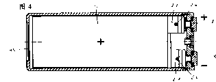
Fig. 3 is by by the storage battery profile that has rectangular enclosure and be provided with extreme head at shell one end of the present invention;
Fig. 4 is along the profile of Fig. 3 A-A line by storage battery;
Fig. 5 is installed in the accumulator cell assembly on the housing parts during the manufacturing procedure of centre;
Fig. 6 is by having rectangular enclosure and being provided with the storage battery profile of extreme head at the shell opposite end; And
Fig. 7 is along B-B line of Fig. 6 profile by storage battery.
Similar or the identical member of different forms of implementation is always used identical symbolic representation in these figure.
Because to various possible structural forms without limits by the present invention, thus below introduce a kind of alkaline battery of airtight and liquid seal of rectangle.Here, refer to as airtight and storage battery liquid seal, gas and liquid can not leak under normal condition of work, but when reaching defined terms, the overvoltage of for example predesignating then can on purpose form opening.
Storage battery 1 is by a shell of being made up of two parts 2,3, and shell has surrounded positive electrode 5 and the negative electrode 6 that is separated from each other by dividing plate 4.At ready operable state, in storage battery 1, inject the electrolyte that figure does not have expression with well-known method.
At extreme 7, position, 8 place, housing designs is double-deck, and it is made up of one deck duroplasts 24 and one deck flexible plastics 14.The flexible plastics of representing with the cross hachure among the figure 14 welds with the duroplasts of representing with oblique section line 24 comprehensively.
When adopting hot thermojet to weld, on flexible plastics 14, spray, to form solder side along the surface that will contact with duroplasts 24.Flexible plastics 14 is by adding plasticizer or by selecting its degree of cross linking, its hardness can being adjusted in the scope that is in known sealing device material.The hardness of duroplasts is adjusted into and makes it to have general outer cover intensity.
As material, can use polyamide, styrene-ethene-butylene-styrol copolymer and/or the polypropylene of improvement.Shell 2,3 parts made of plastic respectively have an overlap that circumferentially extends 9,10, and formation face is fitted in this zone.By means of the ultrasonic weld seam 11 of an annular with overlap 9 and 10 fastened to each other being in the same place.
In by another kind of design of the present invention, on overlap 9 and by overlap 10, constituted a cavity that circumferentially extends 12 with surrounding, this cavity 12 through passage 13 be connected extreme 7, the volume of the flexible plastics 14 at position, 8 place.In flexible plastics 14 surfacings, also be full of this cavity 12.Flexible plastics 14 in cavity 12 thereby constitute one extreme 7, the flexible plastics at position, 8 place 14, and same and duroplasts 24 welds comprehensively.
In the design that another kind can Gong be selected for use, the mechanical connection of two housing parts 2,3 is realized by the fastener 30,31 that is located in the overlap 9,10.At the clamping state, annular flange flange 31 on one of them housing parts 3 is entrapped in made on another housing parts 2 cannelure 30 from behind.Scarf 32 by flange 31 makes these two parts 2,3 be easy to peg graft.Flexible plastics 14 in cavity 12, or be connected with two overlaps 9,10 by surfacing comprehensively; Or only be connected with overlap 10 by surfacing, and fastener 30,31 is close to overlap 9 on the flexible plastics 14 along end face.
In duroplasts 24, imbed glass fibre or other known inert fiber selectively.For this reason, the percentage by volume of glass fibre preferably about 40%.
In housing parts 2,3, be provided with a predetermined breakdown point 15 that is designed to thinning section with duroplasts 24 systems.Area and thickness that predetermined breakdown point 15 has regulation, they are adjusted to and can form an opening from the overvoltage of a regulation of battery cell case inside, and this opening causes pressure to reduce.
For the storage battery of filling with as electrolyte with potassium hydroxide solution, inlet 16 preferably be located at positive extreme 7 near, and section with T shape basically.After electrolyte is filled with, 17 sealings of a T shape of inlet 16 usefulness plug.
Have the band truncated cone shape to draw extreme 7,8 of part 18 in first kind of form of implementation, this draws part 18 and is buckled by a cup-shaped polar cap 19 and cover.Truncated cone shape is drawn part 18 and is abutted on the duroplasts 24 with the side of its expansion planely, and self-centering be fixed in the through hole 20 of a same truncated cone shape.The 19 usefulness spot welding of cup-shaped polar cap with draw part 18 and be connected and closely withhold on flexible plastics 14.One or more solder joints 21 both can also can make before spray flexible plastics 14 after this.The heat energy that brings when selecting to weld so in the known manner under latter event promptly, should make flexible plastics 14 and the duroplasts 24 that is shaped on through hole 20 all can not produce plastic deformations.
In the alternative form of implementation of another kind, extreme 7,8 has the section that is essentially T shape, and the part that it is radially expanded has formed polar cap 19, and transits to draw in the part 18 and become one with it.Drawing part 18 has a hollow cylinder inner chamber 22, and this cavity constitutes a cup-shaped rivet and allows end 23 crimps.Crimp end 23 is buckled on extreme 7, the part duroplasts 24 at position, 8 place from behind.Therefore, polar cap 19 lasting and be pressed on the flexible plastics 14 with fitting tightly.
In the another kind design, between crimp end 23 and duroplasts 24, embed the metal conductive tabs 25 of usefulness, it is connected with electrode 5,6 respectively.By a solder joint 26, contact pin 25 and the lug plate of giving prominence to from the electrode side 27,28 are coupled together.In the shell 2,3 of electric storage means 1, shown in Fig. 2 and 3, electrode 5,6 is stacking from level to level.Another kind of division is as shown in Figure 6, and electrode 5,6 spiralitys ground is folded up being added with under the situation of dividing plate 4 as interface.
In this form of implementation, the opposite end that is preferably in shell respectively has one extreme 7,8, at this moment, the electrode suppor of positive electrode 5 with draw part 18 and directly be connected; And extreme the 8 negative part 18 of drawing directly is connected with negative electrode 6, or is connected with a band 29 with negative electrode 6 contactings.
Because shell is to be divided into two structure, so electrode 5,6 can at first be fixed on extreme 7,8 and housing parts 3 by its brace 27,28 in manufacture process.Fig. 5 has represented a such accumulator cell assembly, wherein, extreme 7,8 flexible plastics 14 and duroplasts 24 inner tight fix.
Such assembly both can be connected with the represented housing parts 2 of accompanying drawing, also can be used for a kind of corresponding shell of electronic equipment.So this storage battery has constituted a part of the device housings of this electronics setting with its shell.
Claims (15)
1. has the storage battery of filling it up with electrolytical gas and liquid seal shell, the electrode that is separated from each other by dividing plate is housed in the shell, electrode is electrically connected with the extreme head that outer end from shell can contact respectively, it is characterized by: shell (2,3) is formed with a kind of flexible plastics (14) and a kind of duroplasts (24) at extreme head (7,8) position, place, their connections fastened to each other, wherein, flexible plastics (14) has constituted the sealing device of drawing part (18) of extreme head (7,8) and/or extreme head (7,8).
2. according to described this storage battery of claim 1, it is characterized by: the flexible plastics (14) and the duroplasts (24) of shell (2,3) link together mutually all sidedly by surfacing.
3. according to claim 1 or 2 described storage batterys, it is characterized by: flexible plastics (14) and duroplasts (24) are formed with a kind of thermoplastics-elastomer, especially a kind of polyamide of improvement, a kind of styrene-ethene-butylene-styrol copolymer and/or polypropylene.
4. according to claim 1,2 or 3 described these storage batterys, it is characterized by: the polar cap (19) of extreme head (7,8) by spot welding with draw part (18) and be connected, and cup-shaped withhold at a part of flexible plastics (14) and be.
5. according to claim 1,2 or 3 described these storage batterys, it is characterized by: part (18) primordial of drawing of extreme head originally upward is cup-shaped rivet, its crimp end (23) fastens the part of duroplasts (24) from behind, is fixed on the flexible plastics (14) thereby make extreme head (7,8) and/or its draw part (18) with fitting tightly.
6. according to the described storage battery of claim 5, it is characterized by: the crimp end (23) of rivet is withheld a conductive tabs (25) that embeds between rivet and the shell from behind.
7. according to the described storage battery of one of aforementioned all claims, it is characterized by: shell (2,3) has comprised a toroidal cavity (12) between two housing parts (2,3), fills up plastics as sealing device in this cavity.
8. according to the described storage battery of claim 7, it is characterized by: flexible plastics (14) in cavity (12) and the flexible plastics (14) at extreme head (7,8) position, place are connected to each other.
9. according to the described storage battery of one of aforementioned all claims, it is characterized by: shell (2,3) uses plastics (14,24) to make fully, and these two housing parts (2,3) are connected to each other together at overlap (9,10) by ultrasonic bonding.
10. according to the described storage battery of one of claim 1 to 8, it is characterized by: shell (2,3) uses plastics (14,24) to make this fully, and these two housing parts (2,3) are by being connected to each other at the made fastener (30,31) of overlap (9,10).
11., it is characterized by: in duroplasts (24), imbed glass fibre according to the described storage battery of one of aforementioned all claims.
12. according to the described storage battery of one of aforementioned all claims, it is characterized by: shell (2,3) is prismatic, especially rectangle, electrode (5,6) is stacking by dividing plate (4) respectively from level to level dividually, wherein, be located at the brace (27,28) of extreme head (7,8) back from electrode (5,6) lateral protrusion, preferably by between the spot welding mutually with relevant extreme head (7,8) electrical connection.
13., it is characterized by: in the part that shell (2,3) is made with duroplasts (24), a predetermined breakdown point (15) that is designed to thinning section is set according to the described storage battery of one of aforementioned all claims.
14. according to the described storage battery of one of aforementioned all claims, it is characterized by: shell (2,3) has an inlet (16), it is set to the distance from positive extreme head (7), less than distance from negative extreme head (8), and, plug (17) sealing that this inlet (16) is a T shape with a section.
15. according to the described storage battery of one of aforementioned all claims, it is characterized by: the shell of storage battery (1) (2,3) constitutes an a kind of part of device housings of electronic equipment.
Applications Claiming Priority (2)
| Application Number | Priority Date | Filing Date | Title |
|---|---|---|---|
| DE4325464A DE4325464A1 (en) | 1993-07-29 | 1993-07-29 | Accumulator with plastic housing |
| DEP4325464.0 | 1993-07-29 |
Publications (2)
| Publication Number | Publication Date |
|---|---|
| CN1128083A true CN1128083A (en) | 1996-07-31 |
| CN1064179C CN1064179C (en) | 2001-04-04 |
Family
ID=6493997
Family Applications (2)
| Application Number | Title | Priority Date | Filing Date |
|---|---|---|---|
| CN94192900A Pending CN1128084A (en) | 1993-07-29 | 1994-07-16 | Gas-tight alkaline accumulator with a valve assembly |
| CN94192902A Expired - Fee Related CN1064179C (en) | 1993-07-29 | 1994-07-16 | Accumulator with plastic housing |
Family Applications Before (1)
| Application Number | Title | Priority Date | Filing Date |
|---|---|---|---|
| CN94192900A Pending CN1128084A (en) | 1993-07-29 | 1994-07-16 | Gas-tight alkaline accumulator with a valve assembly |
Country Status (16)
| Country | Link |
|---|---|
| US (2) | US5789096A (en) |
| EP (2) | EP0711459B1 (en) |
| JP (2) | JPH09501006A (en) |
| KR (1) | KR100309451B1 (en) |
| CN (2) | CN1128084A (en) |
| AT (2) | ATE146901T1 (en) |
| AU (2) | AU7182494A (en) |
| CA (2) | CA2168100A1 (en) |
| DE (3) | DE4325464A1 (en) |
| DK (2) | DK0711459T3 (en) |
| ES (2) | ES2098971T3 (en) |
| FI (2) | FI960373A0 (en) |
| GR (2) | GR3022958T3 (en) |
| NO (2) | NO960213L (en) |
| RU (2) | RU2125754C1 (en) |
| WO (2) | WO1995004381A1 (en) |
Cited By (2)
| Publication number | Priority date | Publication date | Assignee | Title |
|---|---|---|---|---|
| CN102334214A (en) * | 2009-03-27 | 2012-01-25 | 江森自控帅福得先进能源动力系统有限责任公司 | Battery module with sealing ventilating opening chamber |
| CN112421154A (en) * | 2020-10-20 | 2021-02-26 | 浙江南都电源动力股份有限公司 | Lithium battery top cover assembly, lithium battery and preparation method of lithium battery |
Families Citing this family (18)
| Publication number | Priority date | Publication date | Assignee | Title |
|---|---|---|---|---|
| US5865727A (en) * | 1995-08-25 | 1999-02-02 | Asahi Kogaku Kogyo Kabushiki Kaisha | Portable endoscope system |
| DE19544050A1 (en) * | 1995-11-25 | 1997-05-28 | Emmerich Christoph Gmbh Co Kg | Process for the production of prismatic alkaline accumulator cells |
| KR100467426B1 (en) * | 1997-08-06 | 2005-05-03 | 삼성에스디아이 주식회사 | Sealing Container for Lithium Polymer Series Battery |
| SE9704684L (en) * | 1997-12-16 | 1999-06-17 | Ni Me Hydrid Ab | Container for a battery cell |
| KR100553729B1 (en) * | 1999-01-22 | 2006-02-17 | 삼성에스디아이 주식회사 | Case used in secondary battery |
| US6265104B1 (en) | 1999-08-13 | 2001-07-24 | The Gillette Company | Hot-melt seal for metal-air battery |
| US6641949B2 (en) | 2001-04-19 | 2003-11-04 | Zinc Matrix Power, Inc. | Battery vent and method of assembly |
| DE10300008B4 (en) * | 2002-01-09 | 2006-04-27 | Nec Tokin Tochigi Ltd., Utsunomiya | Locked battery and method of making a sealed battery |
| US20040137321A1 (en) * | 2002-11-27 | 2004-07-15 | Jean-Francois Savaria | Casing for an energy storage device |
| US6991872B2 (en) * | 2003-03-26 | 2006-01-31 | The Gillette Company | End cap seal assembly for an electrochemical cell |
| KR100591421B1 (en) * | 2004-09-07 | 2006-06-21 | 삼성에스디아이 주식회사 | Lithium Ion Secondary Battery with Shape Memory Safety Vent |
| CN101488566B (en) * | 2008-01-15 | 2011-08-17 | 财团法人工业技术研究院 | Soft packing cell and air tight type conductive connection structure and assembling process |
| JP5531478B2 (en) | 2009-07-16 | 2014-06-25 | 日産自動車株式会社 | battery pack |
| JP5585174B2 (en) * | 2010-04-07 | 2014-09-10 | 日産自動車株式会社 | Electrolyte injection method and electrolyte injection device |
| US20120225331A1 (en) * | 2011-03-02 | 2012-09-06 | Lithionics, Llc | Battery pack protection system |
| FR2997559B1 (en) * | 2012-10-31 | 2016-12-09 | Renault Sa | THERMAL BATTERY PROTECTION ENVELOPE FOR MOTOR VEHICLE |
| DE102012222836A1 (en) | 2012-12-12 | 2014-06-12 | Robert Bosch Gmbh | Housing for a gas-tight accumulator |
| KR101485897B1 (en) * | 2013-10-29 | 2015-01-26 | 주식회사 비츠로셀 | reserve battery enhancing impact resistant |
Family Cites Families (17)
| Publication number | Priority date | Publication date | Assignee | Title |
|---|---|---|---|---|
| BE755411A (en) * | 1969-08-27 | 1971-03-01 | Union Carbide Corp | RELIEF VALVE FOR SEALED FLUID-TIGHT CONTAINER AND ESPECIALLY FOR ALKALINE GALVANIC CELL |
| FR2292344A1 (en) * | 1974-11-19 | 1976-06-18 | Europ Accumulateurs | Mounting accumulators in plastic housing - by placing plastic spacers in compartments before thermowelding cover |
| FR2359517A1 (en) * | 1976-07-20 | 1978-02-17 | Europ Accumulateurs | Lead acid accumulator with rotationally welded plastic collars - which are around terminals projecting through ultrasonically welded cover |
| US4215187A (en) * | 1977-09-23 | 1980-07-29 | Varta Batterie Aktiengesellschaft | Gas-tight galvanic cell |
| DE2757568C2 (en) * | 1977-12-23 | 1986-05-15 | Varta Batterie Ag, 3000 Hannover | Electric accumulator |
| US4532705A (en) * | 1980-09-26 | 1985-08-06 | Union Carbide Corporation | Method of making an electrochemical cell having a resealable vent closure |
| US4328289A (en) * | 1980-09-26 | 1982-05-04 | Union Carbide Corporation | Electrochemical cell having a resealable vent closure |
| DE3210159C2 (en) * | 1982-03-19 | 1984-02-09 | Accumulatorenfabrik Sonnenschein GmbH, 6470 Büdingen | Gas- and liquid-tight pole seal |
| JPS62147652A (en) * | 1985-12-23 | 1987-07-01 | Matsushita Electric Ind Co Ltd | Sealed lead-acid battery |
| US4780378A (en) * | 1987-09-02 | 1988-10-25 | General Motors Corporation | Battery vent valve |
| US4859547A (en) * | 1987-10-06 | 1989-08-22 | Gates Energy Products, Inc. | Battery terminal and method |
| DE3742026A1 (en) * | 1987-12-11 | 1989-06-22 | Varta Batterie | PLASTIC SEALING ELEMENT FOR GALVANIC PRIME ELEMENTS |
| US5080983A (en) * | 1990-08-16 | 1992-01-14 | Minnesota Mining And Manufacturing Company | Battery |
| US5197994A (en) * | 1990-11-26 | 1993-03-30 | Daniell Battery Manufacturing Co., Inc. | Method of heat sealing a battery |
| US5171647A (en) * | 1990-12-10 | 1992-12-15 | Ovonic Battery Company, Inc. | Hydrogen containment cover assembly for sealing the cell can of a rechargeable electrochemical hydrogen storage cell |
| US5227261A (en) * | 1991-10-15 | 1993-07-13 | Eveready Battery Company, Inc. | Cylindrical electrochemical cells with a diaphragm seal |
| US5229223A (en) * | 1991-10-29 | 1993-07-20 | Eveready Battery Company, Inc. | Air-assisted alkaline cell having a multilayer film seal assembly |
-
1993
- 1993-07-29 DE DE4325464A patent/DE4325464A1/en not_active Withdrawn
-
1994
- 1994-07-16 KR KR1019960700424A patent/KR100309451B1/en not_active IP Right Cessation
- 1994-07-16 CN CN94192900A patent/CN1128084A/en active Pending
- 1994-07-16 AU AU71824/94A patent/AU7182494A/en not_active Abandoned
- 1994-07-16 DE DE59402248T patent/DE59402248D1/en not_active Expired - Fee Related
- 1994-07-16 CA CA002168100A patent/CA2168100A1/en not_active Abandoned
- 1994-07-16 RU RU96103654/09A patent/RU2125754C1/en not_active IP Right Cessation
- 1994-07-16 EP EP94921575A patent/EP0711459B1/en not_active Expired - Lifetime
- 1994-07-16 JP JP7505475A patent/JPH09501006A/en active Pending
- 1994-07-16 AU AU72257/94A patent/AU7225794A/en not_active Abandoned
- 1994-07-16 DK DK94921575.0T patent/DK0711459T3/en active
- 1994-07-16 JP JP7505474A patent/JPH09501005A/en active Pending
- 1994-07-16 ES ES94921575T patent/ES2098971T3/en not_active Expired - Lifetime
- 1994-07-16 DE DE59401425T patent/DE59401425D1/en not_active Expired - Fee Related
- 1994-07-16 US US08/586,763 patent/US5789096A/en not_active Expired - Fee Related
- 1994-07-16 ES ES94920892T patent/ES2100725T3/en not_active Expired - Lifetime
- 1994-07-16 AT AT94921575T patent/ATE146901T1/en not_active IP Right Cessation
- 1994-07-16 DK DK94920892.0T patent/DK0711460T3/en active
- 1994-07-16 AT AT94920892T patent/ATE150905T1/en not_active IP Right Cessation
- 1994-07-16 RU RU96105401/09A patent/RU2123742C1/en not_active IP Right Cessation
- 1994-07-16 EP EP94920892A patent/EP0711460B1/en not_active Expired - Lifetime
- 1994-07-16 CN CN94192902A patent/CN1064179C/en not_active Expired - Fee Related
- 1994-07-16 WO PCT/DE1994/000835 patent/WO1995004381A1/en active IP Right Grant
- 1994-07-16 US US08/586,775 patent/US5783329A/en not_active Expired - Fee Related
- 1994-07-16 CA CA002168101A patent/CA2168101A1/en not_active Abandoned
- 1994-07-16 WO PCT/DE1994/000836 patent/WO1995004380A1/en active IP Right Grant
-
1996
- 1996-01-17 NO NO960213A patent/NO960213L/en not_active Application Discontinuation
- 1996-01-17 NO NO960214A patent/NO960214L/en not_active Application Discontinuation
- 1996-01-26 FI FI960373A patent/FI960373A0/en unknown
- 1996-01-26 FI FI960372A patent/FI960372A/en unknown
-
1997
- 1997-03-27 GR GR970400633T patent/GR3022958T3/en unknown
- 1997-05-05 GR GR970400991T patent/GR3023334T3/en unknown
Cited By (2)
| Publication number | Priority date | Publication date | Assignee | Title |
|---|---|---|---|---|
| CN102334214A (en) * | 2009-03-27 | 2012-01-25 | 江森自控帅福得先进能源动力系统有限责任公司 | Battery module with sealing ventilating opening chamber |
| CN112421154A (en) * | 2020-10-20 | 2021-02-26 | 浙江南都电源动力股份有限公司 | Lithium battery top cover assembly, lithium battery and preparation method of lithium battery |
Also Published As
Similar Documents
| Publication | Publication Date | Title |
|---|---|---|
| CN1064179C (en) | Accumulator with plastic housing | |
| US7700229B2 (en) | Packing, production method of crimp assembly, production method of battery housing lid, and production method of battery | |
| CN101834306B (en) | Sealed battery and method of manufacturing thereof | |
| KR100210271B1 (en) | Sealed alkaline storage battery and its manufacture | |
| CN101916876B (en) | Method and design for externally applied laser welding of internal connections in a high power electrochemical cell | |
| CN1144302C (en) | Explosion-proof seal plate for enclosed type cell and production method thereof | |
| JP3351243B2 (en) | Sealed alkaline storage battery and its manufacturing method | |
| CN102163708A (en) | Rechargeable battery | |
| JP2005150073A (en) | Battery and its manufacturing method | |
| WO2010088332A1 (en) | Modular cid assembly for a lithium ion battery | |
| CN113131054A (en) | Power battery utmost point post packaging structure, top cap, power battery | |
| CN114447413B (en) | Battery cover plate and battery | |
| CN101388440B (en) | Secondary battery | |
| CN113725530A (en) | Power battery top cover component, power battery and battery module | |
| WO2024094179A1 (en) | End cover assembly of battery, battery cell, energy storage device, and electrical apparatus | |
| KR20220162580A (en) | Cylindrical battery can assembly and its manufacturing method | |
| JPH1070053A (en) | Rectangular electrochemical element and manufacture thereof | |
| CN108630880A (en) | Rectangular secondary cell | |
| JP2002298832A (en) | Sealed battery and its liquid injection hole sealing method | |
| KR20010017098A (en) | Prismatic type sealed battery | |
| CN2701082Y (en) | Battery security sealing stopper and sealing cover plate and battery thereof | |
| KR20220051642A (en) | Secondary Battery | |
| JP4222820B2 (en) | Manufacturing method of battery safety mechanism | |
| KR200262297Y1 (en) | Cap assembly in secondary battery | |
| JP3074471B2 (en) | Battery sealed structure |
Legal Events
| Date | Code | Title | Description |
|---|---|---|---|
| C06 | Publication | ||
| PB01 | Publication | ||
| C10 | Entry into substantive examination | ||
| SE01 | Entry into force of request for substantive examination | ||
| C14 | Grant of patent or utility model | ||
| GR01 | Patent grant | ||
| C19 | Lapse of patent right due to non-payment of the annual fee | ||
| CF01 | Termination of patent right due to non-payment of annual fee |