CN112804894A - Aerosol generating device and heating cavity thereof - Google Patents
Aerosol generating device and heating cavity thereof Download PDFInfo
- Publication number
- CN112804894A CN112804894A CN201980066679.5A CN201980066679A CN112804894A CN 112804894 A CN112804894 A CN 112804894A CN 201980066679 A CN201980066679 A CN 201980066679A CN 112804894 A CN112804894 A CN 112804894A
- Authority
- CN
- China
- Prior art keywords
- heating cavity
- aerosol
- heating
- heater
- substrate carrier
- Prior art date
- Legal status (The legal status is an assumption and is not a legal conclusion. Google has not performed a legal analysis and makes no representation as to the accuracy of the status listed.)
- Pending
Links
- 238000010438 heat treatment Methods 0.000 title claims abstract description 478
- 239000000443 aerosol Substances 0.000 title claims abstract description 253
- 239000000758 substrate Substances 0.000 claims abstract description 364
- 230000002829 reductive effect Effects 0.000 claims abstract description 17
- 238000007373 indentation Methods 0.000 claims description 51
- 238000003780 insertion Methods 0.000 claims description 6
- RYGMFSIKBFXOCR-UHFFFAOYSA-N Copper Chemical compound [Cu] RYGMFSIKBFXOCR-UHFFFAOYSA-N 0.000 claims description 5
- 229910052802 copper Inorganic materials 0.000 claims description 5
- 239000010949 copper Substances 0.000 claims description 5
- 230000037431 insertion Effects 0.000 claims description 5
- 230000007423 decrease Effects 0.000 claims description 3
- 229910052751 metal Inorganic materials 0.000 description 76
- 239000002184 metal Substances 0.000 description 76
- 239000003570 air Substances 0.000 description 42
- 239000000463 material Substances 0.000 description 40
- 230000000694 effects Effects 0.000 description 23
- 230000006835 compression Effects 0.000 description 15
- 238000007906 compression Methods 0.000 description 15
- 238000000034 method Methods 0.000 description 14
- 241000208125 Nicotiana Species 0.000 description 12
- 235000002637 Nicotiana tabacum Nutrition 0.000 description 12
- 238000009413 insulation Methods 0.000 description 12
- 230000000875 corresponding effect Effects 0.000 description 11
- 238000004519 manufacturing process Methods 0.000 description 11
- 238000013461 design Methods 0.000 description 10
- 239000007788 liquid Substances 0.000 description 10
- 238000012546 transfer Methods 0.000 description 10
- 230000008901 benefit Effects 0.000 description 7
- 230000008859 change Effects 0.000 description 7
- 239000012530 fluid Substances 0.000 description 7
- 239000011159 matrix material Substances 0.000 description 7
- 239000002245 particle Substances 0.000 description 7
- 230000005855 radiation Effects 0.000 description 7
- 239000007787 solid Substances 0.000 description 7
- 238000007747 plating Methods 0.000 description 6
- 229910001220 stainless steel Inorganic materials 0.000 description 6
- 229910045601 alloy Inorganic materials 0.000 description 5
- 239000000956 alloy Substances 0.000 description 5
- 239000000969 carrier Substances 0.000 description 5
- 238000003825 pressing Methods 0.000 description 5
- 230000008569 process Effects 0.000 description 5
- 239000010935 stainless steel Substances 0.000 description 5
- 230000008016 vaporization Effects 0.000 description 5
- 239000011800 void material Substances 0.000 description 5
- 239000004642 Polyimide Substances 0.000 description 4
- 235000019504 cigarettes Nutrition 0.000 description 4
- 239000000499 gel Substances 0.000 description 4
- 239000011810 insulating material Substances 0.000 description 4
- 239000004033 plastic Substances 0.000 description 4
- 229920001721 polyimide Polymers 0.000 description 4
- PEDCQBHIVMGVHV-UHFFFAOYSA-N Glycerine Chemical compound OCC(O)CO PEDCQBHIVMGVHV-UHFFFAOYSA-N 0.000 description 3
- DNIAPMSPPWPWGF-UHFFFAOYSA-N Propylene glycol Chemical compound CC(O)CO DNIAPMSPPWPWGF-UHFFFAOYSA-N 0.000 description 3
- 230000009471 action Effects 0.000 description 3
- 238000000889 atomisation Methods 0.000 description 3
- 238000005452 bending Methods 0.000 description 3
- 239000003795 chemical substances by application Substances 0.000 description 3
- 238000004891 communication Methods 0.000 description 3
- 238000009713 electroplating Methods 0.000 description 3
- 230000006870 function Effects 0.000 description 3
- 230000000873 masking effect Effects 0.000 description 3
- 150000002739 metals Chemical class 0.000 description 3
- 229920001296 polysiloxane Polymers 0.000 description 3
- 230000009467 reduction Effects 0.000 description 3
- 239000000779 smoke Substances 0.000 description 3
- 230000000391 smoking effect Effects 0.000 description 3
- 239000000126 substance Substances 0.000 description 3
- 235000019505 tobacco product Nutrition 0.000 description 3
- LYCAIKOWRPUZTN-UHFFFAOYSA-N Ethylene glycol Chemical compound OCCO LYCAIKOWRPUZTN-UHFFFAOYSA-N 0.000 description 2
- PXHVJJICTQNCMI-UHFFFAOYSA-N Nickel Chemical compound [Ni] PXHVJJICTQNCMI-UHFFFAOYSA-N 0.000 description 2
- 239000004696 Poly ether ether ketone Substances 0.000 description 2
- 230000004913 activation Effects 0.000 description 2
- 238000012387 aerosolization Methods 0.000 description 2
- 239000012080 ambient air Substances 0.000 description 2
- 230000015572 biosynthetic process Effects 0.000 description 2
- 238000002485 combustion reaction Methods 0.000 description 2
- 238000001816 cooling Methods 0.000 description 2
- 238000000151 deposition Methods 0.000 description 2
- 239000011521 glass Substances 0.000 description 2
- 239000004615 ingredient Substances 0.000 description 2
- 230000003993 interaction Effects 0.000 description 2
- 238000010409 ironing Methods 0.000 description 2
- 230000000670 limiting effect Effects 0.000 description 2
- 239000003595 mist Substances 0.000 description 2
- 238000012544 monitoring process Methods 0.000 description 2
- 238000013021 overheating Methods 0.000 description 2
- 229920002530 polyetherether ketone Polymers 0.000 description 2
- 239000000047 product Substances 0.000 description 2
- 238000009834 vaporization Methods 0.000 description 2
- 230000000007 visual effect Effects 0.000 description 2
- SNICXCGAKADSCV-JTQLQIEISA-N (-)-Nicotine Chemical compound CN1CCC[C@H]1C1=CC=CN=C1 SNICXCGAKADSCV-JTQLQIEISA-N 0.000 description 1
- OKTJSMMVPCPJKN-UHFFFAOYSA-N Carbon Chemical compound [C] OKTJSMMVPCPJKN-UHFFFAOYSA-N 0.000 description 1
- HBBGRARXTFLTSG-UHFFFAOYSA-N Lithium ion Chemical compound [Li+] HBBGRARXTFLTSG-UHFFFAOYSA-N 0.000 description 1
- 230000002730 additional effect Effects 0.000 description 1
- 239000000654 additive Substances 0.000 description 1
- 230000002411 adverse Effects 0.000 description 1
- 238000005275 alloying Methods 0.000 description 1
- WYTGDNHDOZPMIW-RCBQFDQVSA-N alstonine Natural products C1=CC2=C3C=CC=CC3=NC2=C2N1C[C@H]1[C@H](C)OC=C(C(=O)OC)[C@H]1C2 WYTGDNHDOZPMIW-RCBQFDQVSA-N 0.000 description 1
- 238000000137 annealing Methods 0.000 description 1
- 239000012298 atmosphere Substances 0.000 description 1
- 239000011324 bead Substances 0.000 description 1
- 235000019658 bitter taste Nutrition 0.000 description 1
- 239000006227 byproduct Substances 0.000 description 1
- 230000000711 cancerogenic effect Effects 0.000 description 1
- 229910052799 carbon Inorganic materials 0.000 description 1
- 231100000315 carcinogenic Toxicity 0.000 description 1
- 239000000919 ceramic Substances 0.000 description 1
- 238000005229 chemical vapour deposition Methods 0.000 description 1
- 235000019506 cigar Nutrition 0.000 description 1
- 238000004140 cleaning Methods 0.000 description 1
- 238000009833 condensation Methods 0.000 description 1
- 230000001276 controlling effect Effects 0.000 description 1
- 230000008878 coupling Effects 0.000 description 1
- 238000010168 coupling process Methods 0.000 description 1
- 238000005859 coupling reaction Methods 0.000 description 1
- 238000005520 cutting process Methods 0.000 description 1
- 230000001351 cycling effect Effects 0.000 description 1
- 230000003247 decreasing effect Effects 0.000 description 1
- 230000001419 dependent effect Effects 0.000 description 1
- 230000008021 deposition Effects 0.000 description 1
- 238000007865 diluting Methods 0.000 description 1
- 229920001971 elastomer Polymers 0.000 description 1
- 230000005670 electromagnetic radiation Effects 0.000 description 1
- 238000005265 energy consumption Methods 0.000 description 1
- 238000001704 evaporation Methods 0.000 description 1
- 239000000284 extract Substances 0.000 description 1
- 239000000835 fiber Substances 0.000 description 1
- 239000002657 fibrous material Substances 0.000 description 1
- 238000005243 fluidization Methods 0.000 description 1
- 239000006260 foam Substances 0.000 description 1
- 239000006261 foam material Substances 0.000 description 1
- 239000011888 foil Substances 0.000 description 1
- 239000007789 gas Substances 0.000 description 1
- -1 glycerol Chemical class 0.000 description 1
- PCHJSUWPFVWCPO-UHFFFAOYSA-N gold Chemical compound [Au] PCHJSUWPFVWCPO-UHFFFAOYSA-N 0.000 description 1
- 229910052737 gold Inorganic materials 0.000 description 1
- 239000010931 gold Substances 0.000 description 1
- 238000000227 grinding Methods 0.000 description 1
- 230000002650 habitual effect Effects 0.000 description 1
- 239000002654 heat shrinkable material Substances 0.000 description 1
- WGCNASOHLSPBMP-UHFFFAOYSA-N hydroxyacetaldehyde Natural products OCC=O WGCNASOHLSPBMP-UHFFFAOYSA-N 0.000 description 1
- 238000011065 in-situ storage Methods 0.000 description 1
- 230000006698 induction Effects 0.000 description 1
- 230000002401 inhibitory effect Effects 0.000 description 1
- JEIPFZHSYJVQDO-UHFFFAOYSA-N iron(III) oxide Inorganic materials O=[Fe]O[Fe]=O JEIPFZHSYJVQDO-UHFFFAOYSA-N 0.000 description 1
- 229910001416 lithium ion Inorganic materials 0.000 description 1
- 230000007774 longterm Effects 0.000 description 1
- 238000002844 melting Methods 0.000 description 1
- 230000008018 melting Effects 0.000 description 1
- 238000003801 milling Methods 0.000 description 1
- 230000000116 mitigating effect Effects 0.000 description 1
- 239000000203 mixture Substances 0.000 description 1
- 229910052759 nickel Inorganic materials 0.000 description 1
- 229960002715 nicotine Drugs 0.000 description 1
- SNICXCGAKADSCV-UHFFFAOYSA-N nicotine Natural products CN1CCCC1C1=CC=CN=C1 SNICXCGAKADSCV-UHFFFAOYSA-N 0.000 description 1
- 239000012811 non-conductive material Substances 0.000 description 1
- 239000006072 paste Substances 0.000 description 1
- 230000008447 perception Effects 0.000 description 1
- 238000005240 physical vapour deposition Methods 0.000 description 1
- 229920003055 poly(ester-imide) Polymers 0.000 description 1
- 229920005862 polyol Polymers 0.000 description 1
- 150000003077 polyols Chemical class 0.000 description 1
- 239000000843 powder Substances 0.000 description 1
- 238000002360 preparation method Methods 0.000 description 1
- 230000001105 regulatory effect Effects 0.000 description 1
- 230000000717 retained effect Effects 0.000 description 1
- 238000005096 rolling process Methods 0.000 description 1
- 238000006748 scratching Methods 0.000 description 1
- 230000002393 scratching effect Effects 0.000 description 1
- 229920002379 silicone rubber Polymers 0.000 description 1
- 239000004945 silicone rubber Substances 0.000 description 1
- 229910052709 silver Inorganic materials 0.000 description 1
- 239000004332 silver Substances 0.000 description 1
- 239000002904 solvent Substances 0.000 description 1
- 230000003595 spectral effect Effects 0.000 description 1
- 238000001228 spectrum Methods 0.000 description 1
- 238000000859 sublimation Methods 0.000 description 1
- 230000008022 sublimation Effects 0.000 description 1
- 235000000346 sugar Nutrition 0.000 description 1
- 150000008163 sugars Chemical class 0.000 description 1
- 235000019640 taste Nutrition 0.000 description 1
- 230000008719 thickening Effects 0.000 description 1
- 231100000331 toxic Toxicity 0.000 description 1
- 230000002588 toxic effect Effects 0.000 description 1
- 238000010792 warming Methods 0.000 description 1
- 230000037303 wrinkles Effects 0.000 description 1
Images


Classifications
-
- A—HUMAN NECESSITIES
- A24—TOBACCO; CIGARS; CIGARETTES; SIMULATED SMOKING DEVICES; SMOKERS' REQUISITES
- A24F—SMOKERS' REQUISITES; MATCH BOXES; SIMULATED SMOKING DEVICES
- A24F40/00—Electrically operated smoking devices; Component parts thereof; Manufacture thereof; Maintenance or testing thereof; Charging means specially adapted therefor
- A24F40/40—Constructional details, e.g. connection of cartridges and battery parts
- A24F40/46—Shape or structure of electric heating means
-
- A—HUMAN NECESSITIES
- A24—TOBACCO; CIGARS; CIGARETTES; SIMULATED SMOKING DEVICES; SMOKERS' REQUISITES
- A24F—SMOKERS' REQUISITES; MATCH BOXES; SIMULATED SMOKING DEVICES
- A24F40/00—Electrically operated smoking devices; Component parts thereof; Manufacture thereof; Maintenance or testing thereof; Charging means specially adapted therefor
- A24F40/50—Control or monitoring
- A24F40/51—Arrangement of sensors
-
- A—HUMAN NECESSITIES
- A24—TOBACCO; CIGARS; CIGARETTES; SIMULATED SMOKING DEVICES; SMOKERS' REQUISITES
- A24F—SMOKERS' REQUISITES; MATCH BOXES; SIMULATED SMOKING DEVICES
- A24F40/00—Electrically operated smoking devices; Component parts thereof; Manufacture thereof; Maintenance or testing thereof; Charging means specially adapted therefor
- A24F40/70—Manufacture
-
- H—ELECTRICITY
- H02—GENERATION; CONVERSION OR DISTRIBUTION OF ELECTRIC POWER
- H02M—APPARATUS FOR CONVERSION BETWEEN AC AND AC, BETWEEN AC AND DC, OR BETWEEN DC AND DC, AND FOR USE WITH MAINS OR SIMILAR POWER SUPPLY SYSTEMS; CONVERSION OF DC OR AC INPUT POWER INTO SURGE OUTPUT POWER; CONTROL OR REGULATION THEREOF
- H02M1/00—Details of apparatus for conversion
- H02M1/0003—Details of control, feedback or regulation circuits
-
- A—HUMAN NECESSITIES
- A24—TOBACCO; CIGARS; CIGARETTES; SIMULATED SMOKING DEVICES; SMOKERS' REQUISITES
- A24F—SMOKERS' REQUISITES; MATCH BOXES; SIMULATED SMOKING DEVICES
- A24F40/00—Electrically operated smoking devices; Component parts thereof; Manufacture thereof; Maintenance or testing thereof; Charging means specially adapted therefor
- A24F40/20—Devices using solid inhalable precursors
Abstract
An aerosol-generating device (100) has a heating chamber (108) for receiving a substrate carrier (114) containing an aerosol substrate (128). The heating chamber (108) comprises an open end (110) through which the substrate carrier (114) is insertable in a direction along the length of the heating chamber (108). A tubular wall (126) defines an interior volume of the heating cavity (108), and a plurality of engagement elements (140) are each formed from a portion of the tubular wall (126). Each of the plurality of engagement elements (140) is arranged to extend from the inner surface of the tubular wall (126) at different positions around the tubular wall (126) such that the cross-sectional area of the internal volume of the heating cavity (108) is reduced for at least a portion of the length of the heating cavity (108). The engagement elements (140) are used to grip or compress the substrate carrier (114) in the heating chamber (108).
Description
Technical Field
The present disclosure relates to an aerosol generating device and a heating chamber thereof. The present disclosure is particularly applicable to a portable aerosol-generating device that may be self-contained and cryogenic. Such devices may heat, rather than burn, tobacco or other suitable material by conduction, convection, and/or radiation to produce an aerosol for inhalation.
Background
Over the past few years, the popularity and use of risk-reducing or risk-modifying devices (also known as vaporizers) has increased rapidly, helping habitual smokers who want to quit smoking to quit traditional tobacco products such as cigarettes, cigars, cigarillos and cigarettes. Rather than burning tobacco in a conventional tobacco product, various devices and systems for heating or warming the aerosolizable substance are available.
Commonly available devices with reduced or corrected risk are aerosol generating devices that heat a substrate or devices that heat but do not burn. This type of device generates an aerosol or vapour by heating an aerosol substrate, typically comprising moist tobacco leaves or other suitable aerosolizable material, to a temperature typically in the range of 150 ℃ to 300 ℃. Heating, but not burning or burning, the aerosol substrate releases an aerosol that includes the components sought by the user but does not include the toxic and carcinogenic byproducts of burning and burning. In addition, aerosols produced by heating tobacco or other aerosolizable materials typically do not include a burnt or bitter taste resulting from burning and burning that may be unpleasant for the user, and thus, the substrate does not require sugars and other additives that are typically added to such materials to make the smoke and/or vapor more palatable to the user.
In a general sense, it is desirable to rapidly heat the aerosol substrate to a temperature at which the aerosol can be released therefrom, and to maintain the aerosol substrate at that temperature. Obviously, the aerosol will only be released from the aerosol substrate and delivered to the user when there is an airflow through the aerosol substrate.
This type of aerosol generating device is a portable device and therefore energy consumption is an important design consideration. The present invention aims to solve the problems of the prior art devices and to provide an improved aerosol generating device and a heating chamber therefor.
Disclosure of Invention
According to a first aspect of the present disclosure there is provided a heating chamber for an aerosol-generating device, the heating chamber comprising:
an open end through which a substrate carrier comprising an aerosol substrate can be inserted in a direction along the length of the heating chamber;
a tubular wall defining an interior volume of the heating cavity; and
a plurality of engaging elements, each engaging element being formed by a portion of the tubular wall;
wherein each of the plurality of engaging elements is arranged to extend from the inner surface of the tubular wall at different positions around the tubular wall such that the cross-sectional area of the internal volume of the heating cavity is reduced for at least a portion of the length of the heating cavity.
Optionally, the heating cavity further comprises a base at an end of the heating cavity opposite the open end. Preferably, the base is closed, e.g. solid or gas impermeable.
Optionally, the heating cavity comprises a platform extending inwardly (e.g. in an axial direction of the heating cavity) from the base. The platform may include an indentation of the base toward an inside of the heating cavity. The platform may be generally circular. The platform may have a maximum diameter of between 0.5mm and 0.2mm, preferably between 0.35 and 0.45 mm. The platform may be formed by deformation of the base. The platform may further comprise a channel around the platform.
Optionally, the plurality of engagement elements comprises a first engagement element and a second engagement element arranged to extend opposite each other from the inner surface of the tubular wall. There may be three, four or more engagement elements. Typically, the engagement elements are evenly spaced around the tubular wall.
Optionally, each of the plurality of engagement elements comprises a deformation of the tubular wall.
Optionally, the thickness of the tubular wall is substantially constant in the circumferential direction and/or the axial direction. Preferably, the thickness of the tubular wall is less than 150 μm, preferably between 50 μm and 100 μm, and more preferably between 70 μm and 90 μm.
Optionally, the restricted diameter circumscribed by the engagement elements in the heating cavity is between 6.0mm and 6.8mm, preferably between 6.2 and 6.5mm, especially 6.2mm (± 0.5 mm). Optionally, each of the plurality of engagement elements spans a radial distance of between 0.2mm and 0.8mm, most preferably between 0.2mm and 0.4 mm.
Optionally, at least one of the plurality of engaging elements is elongate in a direction along the length of the heating cavity, preferably wherein the or each such engaging element has a length and a width, wherein the length of the or each such engaging element is at least five times its width.
Optionally, at least one of the plurality of engaging elements has a profile in a plane parallel to the length of the heating cavity that is convexly curved towards the interior volume, preferably wherein the profile is a circular arc of a circle.
Optionally, at least one of the plurality of engagement elements has a profile in a plane parallel to the length of the heating cavity (e.g. in a plane of the central axis of the heating cavity) with at least one straight side facing into the interior volume, preferably wherein the profile is polygonal, and still more preferably wherein the profile is trapezoidal in shape. In some examples, the non-parallel sides of the trapezoidal shape may be curved, e.g., convex, or the corners may be curved.
Optionally, at least one of the engagement elements has an upper end located within the interior volume proximate an open end of the heating cavity, wherein the first end is spaced apart from the open end; and/or wherein at least one of the engagement elements has a lower end that is closest to a base of the heating cavity, wherein the lower end is spaced apart from the base.
Optionally, the heating cavity comprises a heater on an outer surface of the tubular wall so as to at least partially and preferably completely overlap at least one of the plurality of engagement elements. The heater may extend along a length of the heating cavity to a greater extent than along at least one of the plurality of engagement elements.
Optionally, the heater comprises a resistive path having first portions extending along the length of the heating cavity, and wherein the first portions are located on the outer surface of the tubular wall at locations other than locations corresponding to the locations of the plurality of engagement elements.
Optionally, the heater comprises a resistive path having second portions extending across the length of the heating cavity, and wherein the second portions are located on the outer surface of the tubular wall at positions corresponding to the positions of the plurality of engagement elements.
Optionally, the heating cavity further comprises a layer between the heater and the outer surface of the tubular wall. The layer preferably has a higher thermal conductivity than the tubular wall, and more preferably the layer is metallic.
Optionally, the layer extends along the length of the heating cavity to a greater extent than the heater, preferably wherein the layer completely covers the outer surface of the tubular wall corresponding to the location of the heater, preferably wherein the layer has a thermal conductivity of at least 150W/mK, and more preferably wherein the layer is a copper layer.
Optionally, further comprising a temperature sensor located on/at the outer surface of the tubular wall, preferably at a position corresponding to the position of one of the plurality of engagement elements.
Optionally, one or more of the plurality of engagement elements is formed by making an indentation into the tubular wall from the outer surface, and the temperature sensor is located in the indentation on the outer surface of the tubular wall.
According to another aspect of the present disclosure, there is provided an aerosol-generating device comprising:
a power source;
a heating chamber as described above;
a heater arranged to provide heat to the heating chamber; and
control circuitry configured to control the supply of electrical power from the electrical power source to the heater.
Optionally, the heating chamber is removable from the aerosol generating device.
According to yet another aspect of the disclosure, a system is provided comprising the above-described heating chamber or aerosol-generating device, and the substrate carrier, wherein the substrate carrier comprises a first portion containing aerosol substrate at a first end of the substrate carrier, and a second portion for aerosol collection, wherein an inner volume of the heating chamber has a width larger than a width of the substrate carrier, but a radius of the inner volume of the heating chamber is smaller than a radius of the substrate carrier where a cross-sectional area of the inner volume of the heating chamber decreases.
Optionally, at least one of the plurality of engagement elements extends inwardly a sufficient distance to form a friction or interference fit with the substrate carrier.
Optionally, at least one of the plurality of engaging elements extends inwardly a sufficient distance to compress the aerosol substrate within the substrate carrier.
Optionally, the substrate carrier comprises a tubular outer layer surrounding at least the substrate carrier and, upon insertion of the substrate carrier into the heating cavity, the tubular outer layer is caused by the plurality of engagement elements to deform inwardly at the location of the plurality of engagement elements and substantially undeformed away from the location of the plurality of engagement elements such that an air gap is provided between the outer layer and the heating cavity facing away from the plurality of engagement elements.
Optionally, at least one of the plurality of engaging elements is shaped and sized such that a portion of such engaging element closest to the open end is substantially aligned with or adjacent to a boundary between a first portion of the substrate carrier containing aerosol substrate and a second portion for aerosol collection when the substrate carrier is fully inserted into the heating cavity.
Preferred embodiments of the present disclosure will now be described, by way of example only, and with reference to the accompanying drawings.
Drawings
Fig. 1 is a schematic perspective view of an aerosol-generating device according to a first embodiment of the present disclosure.
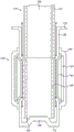
Fig. 2 is a schematic cross-sectional view of the aerosol-generating device of fig. 1 from the side.
Figure 2(a) is a schematic cross-sectional view of the top of the aerosol generating device of figure 1 taken along line X-X shown in figure 2.
Figure 3 is a schematic perspective view of the aerosol-generating device of figure 1 showing a substrate carrier of an aerosol substrate being loaded into the aerosol-generating device.
Figure 4 is a schematic cross-sectional view from the side of the aerosol-generating device of figure 1 showing a substrate carrier of an aerosol substrate being loaded into the aerosol-generating device.
Figure 5 is a schematic perspective view of the aerosol-generating device of figure 1, in which a substrate carrier of an aerosol substrate has been loaded into the aerosol-generating device.
Figure 6 is a schematic cross-sectional view from the side of the aerosol-generating device of figure 1, in which it is shown that a substrate carrier of an aerosol substrate has been loaded into the aerosol-generating device.
Fig. 6(a) is a detailed cross-sectional view of a portion of fig. 6 highlighting the interaction between the substrate carrier and the protrusions in the heating chamber and the corresponding effect on the gas flow path.
Fig. 7 is a plan view of the heater separated from the heating chamber.
Figure 8 is a schematic cross-sectional view from the side of an aerosol generating device having an alternative airflow arrangement according to a second embodiment of the present disclosure.
Fig. 9 is a schematic cross-sectional view from the side of a heating cavity according to a third embodiment of the present disclosure, with pairs of sets of engagement elements offset from each other along the length of the heating cavity.
Fig. 9(a) is a perspective view from above of a heating chamber of an aerosol-generating device according to a third embodiment of the present disclosure.
Fig. 9(b) is a perspective view from below of a heating chamber of an aerosol generating device according to a third embodiment of the present disclosure.
FIG. 10 is a schematic cross-sectional view from the side of a heating cavity having a set of engagement elements of approximately the same width and length in accordance with a fourth embodiment of the present disclosure.
Fig. 10(a) is a perspective view from above of a heating chamber of an aerosol-generating device according to a fourth embodiment of the present disclosure.
Figure 10(b) is a perspective view from below of a heating chamber of an aerosol generating device according to a fourth embodiment of the present disclosure.
FIG. 11 is a schematic cross-sectional view from the side of a heating cavity with a set of engagement elements extending generally perpendicularly from the side wall according to a fifth embodiment of the present disclosure.
Fig. 11(a) is a perspective view from above of a heating chamber of an aerosol-generating device according to a fifth embodiment of the present disclosure.
Figure 11(b) is a perspective view from below of a heating chamber of an aerosol generating device according to a fifth embodiment of the present disclosure.
Fig. 12(a) is a plan view of a heating chamber according to a sixth embodiment of the present invention.
Fig. 12(b) is a plan view of the heating chamber of the sixth embodiment, in which the substrate carrier is inserted.
Fig. 13 is a schematic cross-sectional view from the side of a heating cavity with a set of engagement elements extending in a curvilinear manner from the sidewall according to a seventh embodiment of the present disclosure.
Fig. 13(a) is a perspective view from above of a heating chamber of an aerosol-generating device according to a seventh embodiment of the present disclosure.
Fig. 13(b) is a perspective view from below of a heating chamber of an aerosol generating device according to a seventh embodiment of the present disclosure.
Fig. 14 is a schematic perspective view of a heating chamber according to an eighth embodiment of the present disclosure.
Fig. 15 is a schematic perspective view of a heating chamber according to a ninth embodiment of the present disclosure.
Detailed Description
First embodiment
Referring to fig. 1 and 2, an aerosol-generating device 100, according to a first embodiment of the present disclosure, includes a housing 102 that houses a number of different components of the aerosol-generating device 100. In the first embodiment, the housing 102 is tubular. More specifically, the housing is cylindrical. It should be noted that the housing 102 need not have a tubular or cylindrical shape, but may be any shape, so long as it is sized to accommodate the components described in the different embodiments set forth herein. The housing 102 may be formed from any suitable material or even layers of material. For example, the metal inner layer may be surrounded by the plastic outer layer. This allows the housing 102 to be enjoyably held by a user. Any heat leaking out of the aerosol generating device 100 is distributed by the metal layer around the housing 102, thus preventing the formation of hot spots, while the plastic layer softens the feel of the housing 102. In addition, the plastic layer may help protect the metal layer from rust or scratching, thus improving the long-term appearance of the aerosol-generating device 100.
For convenience, the first end 104 of the aerosol generating device 100 (shown toward the bottom of each of fig. 1-6) is described as the bottom, base, or lower end of the aerosol generating device 100. The second end 106 of the aerosol-generating device 100 (shown towards the top of each of fig. 1-6) is depicted as the top or upper end of the aerosol-generating device 100. In the first embodiment, the first end 104 is a lower end of the housing 102. In use, a user typically orients the aerosol-generating device 100 with the first end 104 facing downward and/or in a distal position relative to the user's mouth, and the second end 106 facing upward and/or in a proximal position relative to the user's mouth.
As shown, the aerosol generating device 100 holds a pair of gaskets 107a, 107b in place at the second end 106 by an interference fit with an interior portion of the housing 102 (only the upper gasket 107a is visible in fig. 1, 3 and 5). In some embodiments, the housing 102 is crimped or bent around an upper one of the gaskets 107a at the second end 106 of the aerosol-generating device 100 to hold the gaskets 107a, 107b in place. The other gasket 107b (i.e., the gasket furthest from the second end 106 of the aerosol generating device 100) bears against a shoulder or annular ridge 109 of the housing 102, thereby preventing the lower gasket 107b from seating beyond a predetermined distance from the second end 106 of the aerosol generating device 100. The gaskets 107a, 107b are formed of a heat insulating material. In this embodiment, the insulation is suitable for use in medical devices, such as Polyetheretherketone (PEEK).
The aerosol generating device 100 has a heating cavity 108 located towards the second end 106 of the aerosol generating device 100. The heating cavity 108 is open towards the second end 106 of the aerosol generating device 100. In other words, the heating cavity 108 has a first open end 110 towards the second end 106 of the aerosol-generating device 100. The heating chamber 108 is kept spaced from the inner surface of the housing 102 by a central aperture fitted through the gaskets 107a, 107 b. This arrangement maintains the heating cavity 108 in a substantially coaxial arrangement with the housing 102. Heating chamber 108 is suspended by a flange 138 of heating chamber 108 at open end 110 of heating chamber 108, sandwiched between the pair of gaskets 107a, 107 b. This means that heat conduction from the heating chamber 108 to the housing 102 generally passes through the gaskets 107a, 107b and is therefore limited by the insulating properties of the gaskets 107a, 107 b. Heat transfer from heating chamber 108 to housing 102 is also reduced, except via gaskets 107a, 107b, due to the presence of air gaps elsewhere around heating chamber 108. In the illustrated embodiment, the flange 138 extends outwardly away from the side wall 126 of the heating cavity 108 a distance of about 1mm, forming an annular structure.
To further improve the thermal insulation of the heating chamber 108, the heating chamber 108 is also surrounded by insulation. In some embodiments, the insulation is a fibrous or foam material, such as batting. In the illustrated embodiment, the insulation includes an insulation member 152 in the form of an insulation cup that includes a double-walled tube 154 and a base 156. In some embodiments, insulating member 152 may comprise a pair of nested cups that enclose an internal cavity therebetween. The internal cavity 158 defined between the walls of the double-walled tube 154 may be filled with an insulating material, such as a fiber, foam, gel, or gas (e.g., at low pressure). In some cases, the lumen 158 may include a vacuum. Advantageously, the vacuum requires a small thickness to achieve high thermal insulation, and the walls of the double-walled tube 154 that enclose the inner cavity 158 can be as small as 100 μm thick, and the overall thickness (two walls and the inner cavity 158 between them) can be as low as 1 mm. The base 156 is an insulating material such as silicone. Because of the flexibility of silicone, the electrical connections 150 of the heater 124 can pass through the base 156, forming a seal around the electrical connections 150.
As shown in fig. 1-6, the aerosol-generating device 100 may include a housing 102, a heating cavity 108, and an insulating member 152, as described in detail above. Fig. 1-6 illustrate a resiliently deformable member 160 located between an outward facing surface of the insulating sidewall 154 and an inner surface of the outer shell 102 to hold the insulating member 152 in place. Elastically deformable member 160 may provide sufficient friction to create an interference fit to hold insulating member 152 in place. The elastically deformable member 160 may be a gasket or O-ring, or other closed loop of material that marks the outward facing surface of the insulated sidewall 154 and the inner surface of the housing 102. The elastically deformable member 160 may be formed of a thermally insulating material (such as silicone). This may provide further thermal insulation between the insulating member 152 and the housing 102. This may therefore reduce the amount of heat transferred to the housing 102 so that a user may comfortably hold the housing 102 while in use. The elastically deformable material can be compressed and deformed, but springs back to its original shape, such as an elastic or rubber material.
As an alternative to this arrangement, the insulating member 152 may be supported by struts that extend between the insulating member 152 and the outer shell 102. The struts may ensure increased rigidity so that the heating cavity 108 is centered within the housing 102, or so that the heating cavity is in a set position. This may be designed such that the heat is evenly distributed throughout the housing 102 so that hot spots do not form.
As yet another alternative, the heating cavity 108 may be secured in the aerosol-generating device 100 by engaging portions on the housing 102 for engaging the side walls 126 at the open end 110 of the heating cavity 108. Attaching heating cavity 108 to housing 102 near open end 110 may allow heat to be quickly dissipated to the environment and ensure a safe fit, since open end 110 is exposed to the greatest cold airflow and thus cools fastest.
It should be noted that in some embodiments, the heating cavity 108 may be removable from the aerosol-generating device 100. Thus, the heating chamber 108 may be easily cleaned or replaced. In such embodiments, heater 124 and electrical connections 150 may not be removable and may reside in situ within insulating member 152.
In the first embodiment, the base 112 of the heating chamber 108 is closed. That is, the heating chamber 108 is cup-shaped. In other embodiments, the base 112 of the heating cavity 108 has one or more holes or is perforated, and the heating cavity 108 remains generally cup-shaped but is not closed at the base 112. In still other embodiments, the base 112 is closed, but the sidewall 126 has one or more holes or is perforated in an area proximate the base 112, e.g., between the heater 124 (or metal layer 144) and the base 112. Heating cavity 108 also has a sidewall 126 between base 112 and open end 110. The side wall 126 and the base 112 are connected to each other. In the first embodiment, the sidewall 126 is tubular. More specifically, the housing is cylindrical. However, in other embodiments, the sidewall 126 has other suitable shapes, such as a tube having an elliptical or polygonal cross-section. Typically, the cross-section is substantially uniform over the length of the heating cavity 108 (without considering the protrusions 140), but in other embodiments the cross-section may vary, for example the cross-section may become smaller towards one end such that the tubular shape is tapered or frustoconical.
In the illustrated embodiment, the heating cavity 108 is unitary, that is, the side wall 126 and the base 112 are formed from a single piece of material, such as by a deep drawing process. This may result in a more robust overall heating chamber 108. Other examples may form the base 112 and/or the flange 138 as separate pieces and then attached to the sidewall 126. This, in turn, may allow the flange 138 and/or the base 112 to be made of a different material than the material from which the side wall 126 is made. The side wall 126 itself is arranged as a thin wall. In some embodiments, the sidewalls are up to 150 μm thick. Typically, the sidewalls 126 are less than 100 μm thick, such as about 90 μm thick, or even about 80 μm thick. In some cases, the sidewalls 126 may be about 50 μm thick, but as the thickness decreases, the failure rate during manufacturing increases. In general, a range of 50 μm to 100 μm is generally suitable, and a range of 70 μm to 90 μm is most preferable. Manufacturing tolerances are up to about + -10 μm, but the parameters provided are intended to be accurate to about + -5 μm.
When the side wall 126 is thin as defined above, the thermal characteristics of the heating cavity 108 change significantly. The resistance to heat transfer through the side wall 126 is negligible because the side wall 126 is too thin, yet heat transfer along the side wall 126 (i.e., parallel to the central axis of the side wall 126 or around the circumference of the side wall) has a small path along which conduction may occur, and thus heat generated by the heater 124 located on the outer surface of the heating chamber 108 remains concentrated near the heater 124 in a direction radially outward from the side wall 126 at the open end, but quickly causes the inner surface of the heating chamber 108 to heat up. In addition, the thin sidewall 126 helps to reduce the thermal mass of the heating chamber 108, thereby improving the overall efficiency of the aerosol generating device 100 because less energy is used to heat the sidewall 126.
The heating chamber 108, and in particular the sidewalls 126 of the heating chamber 108, comprise a material having a thermal conductivity of 50W/mK or less. In a first embodiment, the heating chamber 108 is a metal, preferably stainless steel. Stainless steel has a thermal conductivity of between about 15W/mK and 40W/mK, with the exact value depending on the particular alloy. As another example, a 300 series stainless steel suitable for this purpose has a thermal conductivity of about 16W/mK. Suitable examples include 304, 316, and 321 stainless steels, which have been approved for medical use, are strong, and have a sufficiently low thermal conductivity to allow for the heat concentration described herein.
Materials with thermal conductivities at the levels described above reduce the ability of heat to be conducted away from the area to which heat is applied, as compared to materials with higher thermal conductivities. For example, heat remains concentrated near heater 124. By inhibiting heat from moving to other parts of the aerosol generating device 100, heating efficiency is improved by ensuring that only those parts of the aerosol generating device 100 that are intended to be heated are indeed heated, while those parts that are not intended to be heated are not heated.
Metal is a suitable material because it is strong, plastic, and easy to shape. In addition, the thermal properties of metals vary widely from metal to metal and can be adjusted by careful alloying if desired. In the present application, "metal" refers to elemental (i.e., pure) metals as well as alloys of several metals or other elements (e.g., carbon).
Thus, configuring the heating cavity 108 with a thin sidewall 126, and selecting a material for forming the sidewall 126 with desired thermal properties, ensures that heat can be efficiently conducted through the sidewall 126 and into the aerosol substrate 128. Advantageously, this also reduces the time taken to raise the temperature from ambient to a temperature at which aerosol can be released from the aerosol substrate 128 after initial actuation of the heater.
The heating chamber 108 is formed by deep drawing. This is an efficient way of forming the heating chamber 108 and can be used to provide very thin sidewalls 126. The deep drawing process involves pressing a metal slab with a punch to force it into a forming die. By using a series of progressively smaller die cutters and dies, a tubular structure is formed which has a base at one end and which forms a tube that is deeper than the distance across the tube (which means that the length of the tube is relatively greater than its width, which leads to the term "deep drawing"). Since it is formed in this manner, the side wall of the tube formed in this manner is the same thickness as the original metal plate. Similarly, the base formed in this manner is the same thickness as the initial metal slab. The flange may be formed at the end of the pipe by leaving an outwardly extending rim of the original metal slab at the end of the tubular wall opposite the base (i.e. starting with more material in the blank than is required to form the pipe and the base). Alternatively, the flange may be formed thereafter by a separate step involving one or more of cutting, bending, rolling, swaging, etc.
As previously mentioned, the tubular sidewall 126 of the first embodiment is thinner than the base 112. This can be achieved by first deep drawing the tubular side wall 126 and then ironing the wall. Ironing refers to heating and stretching the tubular sidewall 126 to thin it during the process. In this manner, the tubular sidewall 126 may be sized as described herein.
The thin side wall 126 may be frangible. This can be mitigated by providing additional structural support to the sidewall 126 and by forming the sidewall 126 into a tubular (preferably cylindrical) shape. In some cases, additional structural support is provided as a separate feature, but it should be noted that the flange 138 and base 112 also provide some degree of structural support. Considering the base 112 first, it should be noted that tubes open at both ends are generally susceptible to breakage, while providing the base 112 with increased support for the heating chamber 108 of the present disclosure. It should be noted that in the illustrated embodiment, the base 112 is thicker than the sidewall 126, such as 2 to 10 times the thickness of the sidewall 126. In some cases, this may result in a base 112 having a thickness between 200 μm and 500 μm, for example, a thickness of about 400 μm. The base 112 also has the further purpose of preventing the substrate carrier 114 from being inserted too far into the aerosol-generating device 100. The increased thickness of the base 112 helps prevent damage to the heating cavity 108 in the event that too much force is accidentally used by a user when inserting the substrate carrier 114. Similarly, when a user cleans the heating cavity 108, the user may typically insert an object, such as an elongated brush, through the open end 110 of the heating cavity 108. This means that it is possible for a user to apply more force to base 112 of heating chamber 108 when the elongate object is against base 112 than against side wall 126. Thus, the thickness of the base 112 relative to the sidewall 126 may help prevent damage to the heating cavity 108 during cleaning. In other embodiments, the thickness of the base 112 and the sidewall 126 are the same, which provides some of the benefits set forth above.
The flange 138 extends outwardly from the side wall 126 and has an annular shape extending all the way around the rim of the side wall 126 at the open end 110 of the heating cavity 108. The flange 138 resists bending and shear forces on the side wall 126. For example, lateral deformation of the tube defined by the sidewall 126 may require the flange 138 to buckle. It should be noted that although the flange 138 is shown as extending generally perpendicularly from the side wall 126, the flange 138 may extend obliquely from the side wall 126, e.g., forming a funnel with the side wall 126, while still retaining the advantageous features described above. In some embodiments, the flange 138 is positioned around only a portion of the rim of the sidewall 126, rather than being annular. In the illustrated embodiment, the flange 138 is the same thickness as the sidewall 126, but in other embodiments, the flange 138 is thicker than the sidewall 126 to improve resistance to deformation. Any thickness added for strength of a particular part is balanced against the added thermal mass introduced so that the aerosol generating device 100 as a whole remains robust and efficient.
A plurality of protrusions 140 are formed on the inner surface of the sidewall 126. The width of the protrusion 140 (about the perimeter of the side wall 126) is small relative to its length (parallel to the central axis of the side wall 126, or generally along the direction from the base 112 to the open end 110 of the heating cavity 108). In this example, there are four protrusions 140. Four generally suitable numbers of protrusions 140 for securing the substrate carrier 114 in a central position within the heating chamber 108 will become apparent as the discussion below proceeds. In some embodiments, three protrusions may be sufficient, for example, spaced (evenly) at intervals of about 120 degrees around the circumference of the sidewall 126. The protrusions 140 have a number of different purposes, and the exact form of the protrusions 140 (and corresponding indentations on the outer surface of the sidewall 126) is selected based on the desired effect. In any case, the projections 140 extend toward and engage the substrate carrier 114, and are therefore sometimes referred to as engagement elements. Indeed, the terms "protrusion" and "engagement element" may be used interchangeably herein. Similarly, the term "indentation" may also be used interchangeably with the terms "protrusion" and "engagement element" when protrusion 140 is provided by externally pressing sidewall 126, such as by hydroforming or pressing, or the like. Forming the protrusions 140 by indenting the side walls 126 has the advantage that the protrusions are integral with the side walls 126 and therefore have minimal impact on the heat flow. In addition, the protrusions 140 do not add any thermal mass, which would be the case if additional elements were added to the interior surface of the side walls 126 of the heating cavity 108. In fact, since the protrusions 140 are formed by making indentations to the side wall 126, the thickness of the side wall 126 remains substantially constant in the circumferential direction and/or the axial direction, even where protrusions are provided. Finally, indenting the sidewalls as described increases the strength of the sidewalls 126 by introducing portions that extend transverse to the sidewalls 126, thus providing resistance to bending of the sidewalls 126.
The heating chamber 108 is arranged for receiving a substrate carrier 114. Typically, the substrate carrier comprises an aerosol substrate 128, such as tobacco or another suitable aerosolizable material that can be heated to generate an aerosol for inhalation. In a first embodiment, the heating cavity 108 is sized to receive a single dose of aerosol substrate 128 (also referred to as a "consumable") in the form of the substrate carrier 114, such as shown in fig. 3-6. However, this is not essential, and in other embodiments, the heating cavity 108 is arranged to receive other forms of aerosol substrate 128, such as loose tobacco or otherwise wrapped tobacco.
The aerosol generating device 100 operates in two ways: conducts surface heat from the projections 140 engaging the outer layer 132 of the substrate carrier 114 and heats air in the air gap between the inner surface of the sidewall 126 and the outer surface of the substrate carrier 114. That is, when a user sucks on the aerosol generating device 100, there is convective heating of the aerosol substrate 128 (as described in more detail below) as the heated air is drawn through the aerosol substrate 128. The width and height (i.e., the distance each protrusion 140 extends into the heating cavity 128) increases the surface area of the sidewall 126 that transfers heat to the air, thus allowing the aerosol generating device 100 to reach an effective temperature more quickly.
The protrusions 140 on the inner surface of the side wall 126 extend toward the substrate carrier 114 and do contact the substrate carrier when inserted into the heating cavity 108 (see, e.g., fig. 6). This results in the aerosol substrate 128 also being conductively heated by the outer layer 132 of the substrate carrier 114.
It will be apparent that in order to conduct heat into the aerosol substrate 128, the surface 145 of the projections 140 must interengage with the outer layer 132 of the substrate carrier 114. However, manufacturing tolerances may result in minor variations in the diameter of the substrate carrier 114. Additionally, due to the relatively soft and compressible nature of the substrate carrier 114 and the outer layer 132 of the aerosol substrate 128 retained therein, any damage or rough handling of the substrate carrier 114 may result in a reduction in diameter or a change in shape to an oval or elliptical cross-section in the region where the outer layer 132 is intended to inter-engage with the surface 145 of the projection 140. Thus, any variation in the diameter of the substrate carrier 114 may result in a reduced thermal bond between the outer layer 132 of the substrate carrier 114 and the surface 145 of the protrusion 140, which adversely affects the conduction of heat from the surface 145 of the protrusion 140 through the outer layer 132 of the substrate carrier 114 into the aerosol substrate 128. To mitigate the effects of any diameter variations of the substrate carrier 114 due to manufacturing tolerances or damage, the projections 140 are preferably sized to extend far enough into the heating cavity 108 to cause compression of the substrate carrier 114 and thereby ensure an interference fit between the surfaces 145 of the projections 140 and the outer layer 132 of the substrate carrier 114. Such compression of the outer layer 132 of the matrix carrier 114 may also cause longitudinal marking of the outer layer 132 of the matrix carrier 114 and provide a visual indication that the matrix carrier 114 has been used.
Fig. 6(a) shows an enlarged view of the heating chamber 108 and the substrate carrier 114. It can be seen that arrows B illustrate the airflow path that provides the above-described convective heating. As mentioned above, the heating chamber 108 may be cup-shaped with a sealed, air-impermeable base 112, which means that air must flow down from the side of the substrate carrier 114 to enter the first end 134 of the substrate carrier, since air flow through the sealed, air-impermeable base 112 is not possible. As described above, the projections 140 extend into the heating cavity 108 a sufficient distance to contact at least the outer surface of the substrate carrier 114 and generally cause at least some compression of the substrate carrier. Thus, since the cross-sectional view of fig. 6(a) is cut through the protrusions 140 on the left and right of the figure, there is no air gap all the way along the heating cavity 108 in the plane of the figure. In contrast, the airflow path (arrow B) is shown in dashed lines in the area of the protrusion 140, indicating that the airflow path is located in front of and behind the protrusion 140. Indeed, a comparison with fig. 2(a) shows that the airflow path occupies four equally spaced interstitial regions between the four protrusions 140. There will of course in some cases be more or less than four protrusions 140, in which case the general view that the airflow path exists in the gaps between the protrusions is still true.
Also emphasized in fig. 6(a) is the deformation of the outer surface of the substrate carrier 114 caused by the substrate carrier 114 being forced past the protrusions 140 as it is being inserted into the heating cavity 108. As described above, the distance that the protrusions 140 extend into the heating cavity may advantageously be selected to be sufficiently far to cause compression of any substrate carrier 114. This (sometimes permanent) deformation during heating can help provide stability to the matrix carrier 114 in the following sense: the deformation of the outer layer 132 of the substrate carrier 114 creates a denser region of the aerosol substrate 128 near the first end 134 of the substrate carrier 114. In addition, the resulting contoured outer surface of the substrate carrier 114 provides a gripping action on the edge of the denser region of the aerosol substrate 128 near the first end 134 of the substrate carrier 114. Overall, this reduces the likelihood that any loose aerosol substrate will fall off the first end 134 of the substrate carrier 114, which can result in the heating chamber 108 becoming dirty. This is a useful effect because, as mentioned above, heating the aerosol substrate 128 may cause it to contract, thereby increasing the likelihood that loose aerosol substrate 128 will fall off the first end 134 of the substrate carrier 114. This undesirable effect is mitigated by the deformation effect described.
To ensure that the projections 140 contact the substrate carrier 114 (contact is necessary to cause conductive heating, compression and deformation of the aerosol substrate), manufacturing tolerances for each of the following are taken into account: a protrusion 140; a heating chamber 108; and a substrate carrier 114. For example, the inner diameter of the heating chamber 108 may be 7.6 ± 0.1mm, the substrate 114 carrier may have an outer diameter of 7.0 ± 0.1mm, and the protrusions 140 may have a manufacturing tolerance of ± 0.1 mm. In this example, assuming that the substrate carrier 114 is mounted centrally in the heating chamber 108 (i.e. leaving a uniform gap around the outside of the substrate carrier 114), the gap that each protrusion 140 must span in order to contact the substrate carrier 114 is in the range of 0.2mm to 0.4 mm. In other words, because each protrusion 140 spans a radial distance, the lowest possible value for this example is half the difference between the smallest possible heating cavity 108 diameter and the largest possible substrate carrier 114 diameter, or [ (7.6-0.1) - (7.0+0.1) ]/2 ═ 0.2 mm. The upper end of the range for this example is (for similar reasons) half the difference between the largest possible heating chamber 108 diameter and the smallest possible substrate support 114 diameter, or [ (7.6+0.1) - (7.0-0.1) ]/2 ═ 0.4 mm. To ensure that the protrusions 140 must contact the substrate carrier, it is clear that in this example the protrusions must each extend at least 0.4mm into the heating chamber. However, this does not take into account manufacturing tolerances of the protrusions 140. When a 0.4mm protrusion is desired, the range actually produced is 0.4 ± 0.1mm or varies between 0.3mm and 0.5 mm. Some of which do not span the largest possible gap between the heating chamber 108 and the substrate carrier 114. Thus, the protrusions 140 of the present example should be produced with a nominal protrusion distance of 0.5mm, which results in a range of values between 0.4mm and 0.6 mm. This is sufficient to ensure that the protrusions 140 will always be in contact with the substrate carrier.
Typically, the inner diameter of the heating chamber 108 is written as D + -deltaDThe outer diameter of the substrate carrier 114 is written as d + -deltadAnd the distance that protrusion 140 extends into heating chamber 108 is written as L ± δLThe distance that the protrusion 140 is intended to extend into the heating cavity should be chosen as:

wherein, | δDI refers to the magnitude of the manufacturing tolerance of the inner diameter of the heating chamber 108, | δdI refers to the magnitude of the manufacturing tolerance of the outer diameter of the substrate carrier 114, and | δLBy | is meant the magnitude of the manufacturing tolerance for the distance that the protrusion 140 extends into the heating cavity 108. For the avoidance of doubt, the internal diameter in the heating chamber 108 is D ± δDWhen the thickness is 7.6 ± 0.1mm, the absolute value of | δ isD|=0.1mm。
Furthermore, manufacturing tolerances may result in minor variations in the density of the aerosol substrate 128 within the substrate carrier 114. Such variations in the density of the aerosol substrate 128 may exist in both the axial and radial directions within a single substrate carrier 114, or between different substrate carriers 114 manufactured in the same batch. Thus, it is also apparent that to ensure relatively uniform heat conduction within the aerosol substrate 128 within a particular substrate carrier 114, it is important that the density of the aerosol substrate 128 is also relatively uniform. To mitigate the effect of any inconsistencies in the density of the aerosol substrate 128, the projections 140 may be sized to extend far enough into the heating cavity 108 to compress the aerosol substrate 128 within the substrate carrier 114, which may improve heat conduction through the aerosol substrate 128 by eliminating air gaps. In the illustrated embodiment, it is suitable that the protrusion 140 extends approximately 0.4mm into the heating cavity 108. In other examples, the distance that the protrusion 140 extends into the heating cavity 108 may be defined as a percentage of the distance across the heating cavity 108. For example, the protrusion 140 may extend a distance of between 3% and 7%, such as about 5%, of the distance across the heating cavity 108. In another embodiment, the restricted diameter circumscribed by protrusion 140 in heating cavity 108 is between 6.0mm and 6.8mm, more preferably between 6.2 and 6.5mm, and particularly 6.2mm (± 0.5 mm). Each of the plurality of protrusions 140 spans a radial distance of between 0.2mm and 0.8mm, most preferably between 0.2mm and 0.4 mm.
With respect to the protrusions/indentations 140, the width corresponds to the distance around the perimeter of the side wall 126. Similarly, its length extends transversely thereto, generally from the base 112 of the heating cavity 108 to the open end or to the flange 138, and its height corresponds to the distance that the protrusion extends from the side wall 126. It should be noted that the spaces between adjacent projections 140, sidewalls 126, and outer layer 132 substrate carriers 114 define an area through which air may flow. The result is that the smaller the distance between adjacent projections 140 and/or the height of the projections 140 (i.e., the distance the projections 140 extend into the heating cavity 108), the more difficult it is for a user to suck to draw air through the aerosol-generating device 100 (referred to as increased resistance to suction). It will be apparent that (assuming that the projections 140 are contacting the outer layer 132 of the substrate carrier 114) it is the width of the projections 140 that defines the reduction in gas flow path between the side walls 126 and the substrate carrier 114. Conversely, (again assuming the projections 140 are contacting the outer layer 132 of the substrate carrier 114), increasing the height of the projections 140 results in more compression of the aerosol substrate, which eliminates air gaps in the aerosol substrate 128 and also increases the resistance to draw. These two parameters can be adjusted to give a satisfactory resistance to suction, neither too low nor too high. The heating chamber 108 can also be made larger to increase the airflow path between the side wall 126 and the substrate carrier 114, but there is a practical limit before the heater 124 begins to fail due to too large a gap. Typically, a gap of 0.2mm to 0.4mm or 0.2mm to 0.3mm around the outer surface of the substrate carrier 114 is a good compromise, which allows for fine tuning of the suction resistance within acceptable values by varying the dimensions of the protrusions 140. The air gap around the outside of the substrate carrier 114 can also be varied by varying the number of protrusions 140. Any number of protrusions 140 (from one up) provides at least some of the advantages set forth herein (increased heating area, providing compression, providing conductive heating of the aerosol substrate 128, tuning the air gap, etc.). Four is the minimum number to reliably maintain the substrate carrier 114 in centered (i.e., coaxial) alignment with the heating chamber 108. In another possible design, there are only three protrusions distributed at a distance of 120 ° from each other. The design of less than four protrusions 140 tends to allow for the following: the substrate carrier 114 is pressed against a portion of the side wall 126 between the two protrusions 140. It is clear that for limited space, providing a very large number of protrusions (e.g., thirty or more) tends to be the case: with little or no gaps therebetween, which may completely close the airflow path between the outer surface of the substrate carrier 114 and the inner surface of the sidewall 126, thereby greatly reducing the ability of the aerosol generating device to provide convective heating. However, this design may still be used in combination with the possibility of providing a hole in the centre of the base 112 to define the airflow channel. Generally, the protrusions 140 are evenly spaced around the perimeter of the sidewall 126, which may help provide uniform compression and heating, but some variations may have an asymmetric placement, depending on the exact effect desired.
It is clear that the size and number of protrusions 140 also allows to adjust the balance between conductive and convective heating. By increasing the width of the protrusions 140 contacting the substrate carrier 114 (the distance the protrusions 140 extend around the perimeter of the side wall 126), the available perimeter of the side face 126 acting as an airflow channel (arrow B in fig. 6 and 6 (a)) is reduced, thus reducing the convective heating provided by the aerosol generating device 100. However, since the wider protrusions 140 are in contact with the substrate carrier 114 over a greater part of the perimeter, the conductive heating provided by the aerosol-generating device 100 is increased. A similar effect is seen if more protrusions 140 are added, as the available perimeter of the sidewall 126 for convection is reduced, while increasing the conduction path by increasing the total contact surface area between the protrusions 140 and the substrate carrier 114. It should be noted that increasing the length of the protrusions 140 also reduces the volume of air in the heating cavity 108 that is heated by the heater 124 and reduces convective heating, while increasing the contact surface area between the protrusions 140 and the substrate carrier and increasing conductive heating. Increasing the distance each protrusion 140 extends into the heating cavity 108 may improve conductive heating without significantly reducing convective heating. Accordingly, the aerosol-generating device 100 may be designed to balance the conductive heating type and the convective heating type by varying the number and size of the protrusions 140, as described above. The heat concentration effect due to the relatively thin sidewall 126 and the use of a relatively low thermal conductivity material (e.g., stainless steel) ensures that conductive heating is a suitable way to transfer heat to the substrate carrier 114 and subsequently to the aerosol substrate 128, as the heated portion of the sidewall 126 may generally correspond to the location of the projections 140, meaning that the generated heat is conducted by the projections 140 to the substrate carrier 114 rather than away therefrom. Heating of the side 126 at locations that are heated but do not correspond to the protrusions 140 creates the convective heating described above.
As shown in fig. 1-6, the protrusion 140 is elongated, that is, the protrusion extends a length greater than its width. In some cases, the protrusion 140 may have a length that is five times, ten times, or even twenty-five times its width. For example, as described above, the protrusion 140 may extend 0.4mm into the heating cavity 108, and in one example may further be 0.5mm wide and 12mm long. These dimensions apply to the heating chamber 108 having a length between 30mm and 40 mm. In this example, the protrusions 140 do not extend the full length of the heating cavity 108, as in the example given, the protrusions are shorter than the heating cavity 108. Thus, the tabs 140 each have a top edge 142a and a bottom edge 142 b. The top edge 142a is the portion of the projection 140 that is located closest to the open end 110 of the heating cavity 108 and also closest to the flange 138. Bottom edge 142b is the end of tab 140 that is located closest to base 112. Above top edge 142a (closer to the open end than top edge 142a) and below bottom edge 142b (closer to base 112 than bottom edge 142b), it can be seen that sidewall 126 is free of protrusions 140, that is, sidewall 126 is free of deformations or indentations in these portions. In some examples, the protrusion 140 is longer and extends all the way to the top and/or bottom of the sidewall 126, such that one or both of the following holds: the top edge 142a is aligned with the open end 110 (or flange 138) of the heating cavity 108; and, bottom edge 142b is aligned with base 112. In such cases, in fact, the top edge 142a and/or the bottom edge 142b may not even be present.
It may be advantageous for the protrusion 140 not to extend all the way along the length of the heating cavity 108 (e.g., from the base 112 to the flange 138). At the upper end, as will be described below, the top edge 142a of the protrusion 140 may serve as an indicator for the user to ensure that they do not over-insert the substrate carrier 114 into the aerosol-generating device 100. However, it can be used not only to heat the area of the substrate carrier 114 containing the aerosol substrate 128, but also to other areas. This is because once the aerosol is generated, it is advantageous to keep its temperature high (above room temperature, but not so high as to burn the user) to prevent re-condensation which in turn will reduce the user experience. Thus, the effective heating area of the heating cavity 108 extends past (i.e., above the heating cavity 108, closer to the open end) the intended location of the aerosol substrate 128. This means that the heating cavity 108 extends higher than the upper edge 142a of the protrusion 140, or equivalently that the protrusion 140 does not extend all the way up to the open end of the heating cavity 108. Similarly, compression of the aerosol substrate 128 at the end 134 of the substrate carrier 114 inserted into the heating cavity 108 may cause some of the aerosol substrate 128 to fall out of the substrate carrier 114 and contaminate the heating cavity 108. Thus, it may be advantageous to place the lower edge 142b of the projection 140 farther from the base 112 than the intended location of the end 134 of the substrate carrier 114.
In some embodiments, the protrusion 140 is not elongated and has a width that is approximately the same as its length. For example, the width of the protrusion may be the same as the height (e.g. having a square or circular profile as seen in the radial direction), or the length of the protrusion may be two to five times the width. It should be noted that the centering effect provided by the projections 140 is achievable even in the case where the projections 140 are not elongate. In some examples, there may be multiple sets of protrusions 140, for example, an upper set of protrusions proximate to the open end of the heating cavity 108, a lower set of protrusions spaced apart from the upper set of protrusions, positioned proximate to the base 112. This may help ensure that the substrate carriers 114 remain in a coaxial arrangement while reducing the draw resistance introduced by a single set of protrusions 140 over the same distance. The two sets of protrusions 140 may be substantially identical, or their length or width or the number or position of protrusions 140 disposed about the sidewall 126 may vary.
In side view, the protrusion 140 is shown as having a trapezoidal profile. What is meant here is that the profile along the length of each protrusion 140 (e.g., the lengthwise central cross-section of the protrusion 140) is generally trapezoidal. That is, upper edge 142a is generally planar and tapers to merge with sidewall 126 proximate open end 110 of heating cavity 108. In other words, the upper edge 142a is contoured in a chamfered shape. Similarly, the protrusion 140 has a lower portion 142b that is generally planar and tapers to merge with the sidewall 126 proximate the base 112 of the heating cavity 108. That is, the lower edge 142b is contoured in a chamfered shape. In other embodiments, the upper edge 142a and/or the lower edge 142b do not taper toward the sidewall 126, but extend from the sidewall 126 at an angle of about 90 degrees. In still other embodiments, upper edge 142a and/or lower edge 142b have a curvilinear or rounded shape. Bridging the upper edge 142a and the lower edge 142b is a generally planar region that contacts and/or compresses the substrate carrier 114. The planar contact portion may help provide uniform compression and conductive heating. In other examples, the planar portion may instead be a curved portion that curves outward to contact the substrate carrier 128, such as having a polygonal or curved profile (e.g., a portion of a circle).
In the case where the projections 140 have upper edges 142a, the projections 140 also function to prevent over-insertion of the substrate carrier 114. As best shown in fig. 4 and 6, the substrate carrier 114 has a lower portion containing the aerosol substrate 128, which lower portion ends halfway along the substrate carrier 114 at the boundary of the aerosol substrate 128. The aerosol substrate 128 is generally more compressible than other areas 130 of the substrate carrier 114. Thus, due to the reduced compressibility of the other regions 130 of the substrate carrier 114, a user inserting the substrate carrier 114 feels an increased resistance when the upper edges 142a of the projections 140 are aligned with the boundaries of the aerosol substrate 128. To achieve this, the portion of the base 112 that the substrate carrier 114 contacts should be spaced from the top edge 142a of the projection 140 by the same distance as the length of the substrate carrier 114 occupied by the aerosol substrate 128. In some examples, the aerosol substrate 128 occupies about 20mm of the substrate carrier 114, such that when the substrate carrier 114 is inserted into the heating cavity 108, the spacing between the top edge 142a of the protrusion 140 and the portion of the base that the substrate carrier contacts is also about 20 mm.
As shown, the base 112 also includes a platform 148. The platform 148 is formed by a single step of pressing the base 112 from below (e.g., by hydroforming, mechanical pressure, as part of the formation of the heating cavity 108) to leave an indentation on the outer surface (lower face) of the base 112 and the platform 148 on the inner surface (upper face, inside the heating cavity 108) of the base 112. When the platform 148 is formed in this manner, such as by corresponding indentations, these terms may be used interchangeably. In other cases, the platform 148 may be formed from a separate piece that is separately attached to the base 112, or by milling away a portion of the base 112 leaving the platform 148; in either case, there need not be a corresponding indentation. The latter case may provide more possibilities in terms of the shape of the platform 148, as this is not dependent on deformation of the base 112, which (although in a convenient manner) limits the complexity of the shape that can be selected. While the shapes shown are generally circular, there are of course a wide variety of shapes that will achieve the intended effects set forth in detail herein, including but not limited to: polygonal shapes, curvilinear shapes, including shapes of one or more of these types. Indeed, although shown as a centrally located platform 148, in some cases there may be one or more platform elements spaced from the center, for example at the edges of the heating cavity 108. Typically, the platform 148 has a generally flat top, but hemispherical platforms or platforms having a rounded dome shape at the top are also contemplated.
As mentioned above, the distance between the top edge 142a of the projection 140 and the portion of the base 112 that the substrate carrier 114 contacts may be carefully selected to match the length of the aerosol substrate 128 to indicate to the user that they have inserted the substrate carrier 114 into the aerosol-generating device 100 as far as it should be. In the absence of the platform 148 on the base 112, this simply means that the distance from the base 112 to the top edge 142a of the projection 140 should match the length of the aerosol substrate 128. When the platform 148 is present, the length of the aerosol substrate 128 should correspond to the distance between the top edge 142a of the projection 140 and the uppermost portion of the platform 148 (i.e., the portion closest to the open end 110 of the heating cavity 108 in some examples). In yet another example, the distance between the top edge 142a of the projection 140 and the uppermost portion of the platform 148 is slightly less than the length of the aerosol substrate 128. This means that the tip 134 of the substrate carrier 114 must extend slightly past the uppermost portion of the platform 148, thereby causing the aerosol substrate 128 at the end 134 of the substrate carrier 114 to be compressed. In fact, this compression effect may occur even in the absence of the protrusions 140 on the inner surface of the sidewall 126. This compression may help prevent aerosol substrate 128 at the end 134 of the substrate carrier 114 from falling out into the heating chamber 108, thereby reducing the need to clean the heating chamber 108, which may be a complex and difficult task. In addition, this compression helps to compress the end 134 of the substrate carrier 114, thereby mitigating the above-mentioned effects when compressing this area improperly using the projections 140 extending from the side wall 126, as the projections tend to increase the likelihood that the aerosol substrate 128 will fall out of the substrate carrier 114.
The platform 148 also provides an area that can collect any aerosol substrate 128 that falls out of the substrate carrier 114 without obstructing the airflow path into the tip 134 of the substrate carrier 114. For example, the platform 148 divides the lower end of the heating chamber 108 (i.e., the portion closest to the base 112) into a raised portion that forms the platform 148 and a lower portion that forms the remainder of the base 112. The lower portion may receive loose small amounts of aerosol substrate 128 falling out of the substrate carrier 114, while air may still flow through these loose small amounts of aerosol substrate 128 into the end of the substrate carrier 114. To achieve this effect, the platform 148 may be about 1mm higher than the rest of the base 112. The platform 148 may have a diameter that is smaller than the diameter of the substrate carrier 114 such that the platform does not impede the flow of air through the aerosol substrate 128. Preferably, the platform 18 has a diameter of between 0.5mm and 0.2mm, most preferably between 0.45mm and 0.35mm, for example 0.4mm (± 0.03 mm).
The aerosol generating device 100 has a user operable button 116. In the first embodiment, the user operable buttons 116 are located on a side wall 118 of the housing 102. The user-operable button 116 is arranged such that upon actuation of the user-operable button 116, for example by pressing the user-operable button 116, the aerosol-generating device 100 is activated to heat the aerosol substrate 128 to generate an aerosol for inhalation. In some embodiments, the user-operable button 116 is also arranged to allow a user to activate other functions of the aerosol generating device 100, and/or to illuminate to indicate the status of the aerosol generating device 100. In other examples, a separate light or lights (e.g., one or more LEDs or other suitable light sources) may be provided to indicate the status of the aerosol-generating device 100. In this context, a state may refer to one or more of the following: battery remaining power, heater status (e.g., on, off, wrong, etc.), device status (e.g., ready to suck or not suck), or other status indications, such as error patterns, indications of the number of suckings spent or remaining before power is exhausted or the entire substrate carrier 114, and so forth.
In a first embodiment, the aerosol generating device 100 is electrically powered. That is, the aerosol generating device is arranged to heat the aerosol substrate 128 using electrical power. For this purpose, the aerosol-generating device 100 has a power source 120, for example a battery. The power source 120 is coupled to control circuitry 122. The control circuitry 122 is in turn coupled to a heater 124. A user operable button 116 is arranged for coupling and decoupling the power supply 120 to and from the heater 124 via control circuitry 122. In this embodiment, the power source 120 is positioned towards the first end 104 of the aerosol generating device 100. This allows the power source 120 to be spaced apart from the heater 124, which is positioned towards the second end 106 of the aerosol generating device 100. In other embodiments, the heating cavity 108 is heated in other ways, such as by burning a combustible gas.
The electrical connection tracks 150 are shown as part of the heater 124, but may be replaced with wires or other connection elements in some embodiments. Electrical connection 150 is used to provide power to heating element 164 and forms an electrical circuit with power source 120. The electrical connection tracks 150 are shown extending vertically downward from the heating element 164. With heater 124 in place, electrical connections 150 extend through base 112 of heating chamber 108 and through base 156 of insulating member 152 to connect with control circuitry 122.
The backing film 166 may be a single sheet with the heating element 164 attached thereto, or may form an envelope (envelope) that sandwiches the heating element between the two sheets 166a, 166 b. In some embodiments, the backing film 166 is formed of polyimide. In some embodiments, the thickness of the backing film 166 is minimized in order to reduce the thermal mass of the heater 124. For example, the thickness of the backing film 166 may be 50 μm, or 40 μm, or 25 μm.
The heating element 164 is attached to the sidewall 108. In fig. 7, heating element 164 is configured to wrap around heating cavity 108 by careful selection of the size of heater 124. This ensures that the heat generated by heater 124 is distributed substantially evenly around the surface covered by heater 124. It should be noted that in some examples, heater 124 may wrap an integer number of turns around heating chamber 108, rather than wrapping a full turn.
It should also be noted that the height of the heater 124 is about 14mm to 15 mm. The circumference (or length before being applied to the heating chamber 108) of the heater 124 is about 24mm to 25 mm. The height of the heating element 164 may be less than 14 mm. This enables heating element 164 to be positioned entirely within backing film 166 of heater 124, which has a boundary around heating element 164. Thus, in some embodiments, the area covered by heater 124 may be about 3.75cm2。
The power used by the heater 124 is provided by a power source 120, which in this embodiment is in the form of a battery cell (or battery). The voltage provided by the power supply 120 is a regulated voltage or a boosted voltage. For example, the power supply 120 may be configured to generate a voltage in the range of 2.8V to 4.2V. In one example, the power supply 120 is configured to generate a voltage of 3.7V. Taking an example resistance of 0.6 Ω and an example voltage of 3.7V for heating element 164 in one embodiment, this will produce a power output of approximately 30W in heating element 164. It should be noted that the power output may be between 15W and 50W based on exemplary resistance and voltage. The battery cells forming the power source 120 may be rechargeable battery cells, or alternatively may be disposable battery cells 120. The power supply is typically configured to provide power for 20 or more thermal cycles. This enables a user to use a complete pack of 20 substrate carriers 114 with a single charge of the aerosol-generating device 100. The battery cells may be lithium ion battery cells, or any other type of commercially available battery cells. For example, it may be a 18650 battery cell or a 18350 battery cell. If the battery cell is a 18350 battery cell, the aerosol-generating device 100 may be configured to store sufficient charge for 12 thermal cycles or indeed 20 thermal cycles to allow a user to consume 12 or even 20 substrate carriers 114.
One important value for heater 124 is the power per unit area it generates. This is a measure of how much heat the heater 124 can provide to the area in contact with it (in this case, the heating chamber 108). For the example described, this range is from 4W/cm2To 13.5W/cm2. The heater is typically rated at 2W/cm2And 10W/cm2Depending on the design. Thus, for some of these embodiments, a layer of copper or other conductive metal 144 may be disposed on the heating chamber 108 to effectively conduct heat from the heater 124 and reduce the likelihood of damage to the heater 124.
The power delivered by heater 124 may be constant in some embodiments, but may not be constant in other embodiments. For example, the heater 124 may provide variable power through a duty cycle, or more specifically, in a pulse width modulation cycle. This allows power to be delivered in pulses, and the time-averaged power output of heater 124 is easily controlled by simply selecting the ratio of the "on" time to the "off" time. The power level output by heater 124 may also be controlled by additional control means, such as current or voltage manipulation.
As shown in fig. 7, the aerosol generating device 100 has a temperature sensor 170 for detecting the temperature of the heater 124 or the temperature of the environment around the heater 124. The temperature sensor 170 may be, for example, a thermistor, a thermocouple, or any other thermometer. For example, the thermistor may be formed from a glass bead that encapsulates a resistive material connected to a voltmeter and has a known current flowing through the material. Thus, as the temperature of the glass changes, the resistance of the resistive material changes in a predictable manner, and such temperature can be determined by the voltage drop across the resistive material at a constant current (constant voltage mode is also possible). In some embodiments, the temperature sensor 170 is positioned on a surface of the heating cavity 108, such as in an indentation formed in an outer surface of the heating cavity 108. The indentation may be one of those described elsewhere herein, for example as part of the protrusion 140, or the indentation may be an indentation specifically configured to receive the temperature sensor 170. In the illustrated embodiment, the temperature sensor 170 is disposed on the backing layer 166 of the heater 124. In other embodiments, the temperature sensor 170 is integral with the heating element 164 of the heater 124 in the sense that: the temperature is detected by monitoring the change in resistance of the heating element 164.
In the aerosol-generating device 100 of the first embodiment, the moment at which the first suck occurs after activation of the aerosol-generating device 100 is an important parameter. A user of the aerosol generating device 100 will find it desirable to begin inhalation of the aerosol from the substrate carrier 128 as soon as possible with a minimum lag time between activation of the aerosol generating device 100 and inhalation of the aerosol from the substrate carrier 128. Thus, during the first stage heating, the power supply 120 provides 100% of the available power to the heater 124, for example by setting the duty cycle to be always on or by manipulating the product of the voltage and current to a maximum possible value. This may be for a period of 30 seconds, or more preferably for a period of 20 seconds, or for any period until the temperature sensor 170 gives a reading corresponding to 240 ℃. Typically, the substrate carrier 114 may perform optimally at 180 ℃, but it may be advantageous to heat the temperature sensor 170 above this temperature so that the user may extract the aerosol from the substrate carrier 114 as quickly as possible. This is done because the temperature of the aerosol substrate 128 generally lags (i.e., is lower than) the temperature detected by the temperature sensor 170, because the aerosol substrate 128 is heated by convection of warm air through the aerosol substrate 128 and to some extent by conduction between the projections 140 and the outer surface of the substrate carrier 114. In contrast, the temperature sensor 170 maintains good thermal contact with the heater 124, and thus the measured temperature is close to the temperature of the heater 124 rather than the aerosol substrate 128. In practice, it can be difficult to accurately measure the temperature of the aerosol substrate 128, so the heating cycle is typically determined empirically, where different heating profiles and heater temperatures are tried, and the aerosol produced by the aerosol substrate 128 is monitored for the different aerosol components formed at that temperature. The optimal cycle provides aerosol as quickly as possible, but avoids combustion products resulting from overheating of the aerosol substrate 128.
The temperature detected by the temperature sensor 170 may be used to set the power level delivered by the battery cell 120, for example, by forming a feedback loop in which the temperature detected by the temperature sensor 170 is used to control the heater power cycle. The heating cycle described below may be used in situations where a user desires to consume a single substrate carrier 114.
In the first embodiment, heater 124 extends around heating chamber 108. That is, heater 124 surrounds heating chamber 108. In more detail, heater 124 extends around a sidewall 126 of heating cavity 108, but does not extend around base 112 of heating cavity 108. Heater 124 does not extend over the entire side wall 126 of heating chamber 108. Rather, the heater extends all the way around the side wall 126, but only for a portion of the length of the side wall 126, which in this context is from the base 112 to the open end 110 of the heating chamber 108. In other embodiments, heater 124 extends the entire length of sidewall 126. In still other embodiments, heater 124 includes two heating portions separated by a gap, while leaving a central portion of heating cavity 108 uncovered, e.g., a portion of sidewall 126 intermediate base 112 and open end 110 of heating cavity 108. In other embodiments, because the heating chamber 108 is cup-shaped, the heater 110 is cup-like, e.g., the heater extends completely around the base 112 of the heating chamber 108. In still other embodiments, heater 124 includes a plurality of heating elements 164 distributed about heating cavity 108. In some embodiments, there is a space between the heating elements 164; in other embodiments, the heating elements overlap one another. In some embodiments, the heating elements 164 may be spaced apart (e.g., laterally) around the circumference of the heating cavity 108 or sidewall 126, and in other embodiments, the heating elements 164 may be spaced apart (e.g., longitudinally) along the length of the heating cavity 108 or sidewall 126. It should be understood that the heater 124 of the first embodiment is disposed on the outer surface of the heating chamber 108, outside of the heating chamber 108. Heater 124 is placed in good thermal contact with heating chamber 108 to allow good heat transfer between heater 124 and heating chamber 108.
The metal layer 144 may be formed of copper or any other material (e.g., metal or alloy) of high thermal conductivity, such as gold or silver. In this context, high thermal conductivity may refer to a metal or alloy having a thermal conductivity of 150W/mK or more. The metal layer 144 may be applied by any suitable method, such as electroplating. Other methods of applying the layer 144 include attaching a metal strip to the heating chamber 108, chemical vapor deposition, physical vapor deposition, and the like. While electroplating is a convenient method for applying the layer 144, the portions that need to be plated with the layer 144 are conductive. Other deposition methods are not, and these other methods offer the possibility that the heating chamber 108 is formed of a non-conductive material (e.g., ceramic) that may have useful thermal properties. Also, when a layer is described as metallic, although this should generally be understood as "formed from a metal or alloy," in this context refers to a relatively high thermal conductivity material (> 150W/mK). When the metal layer 144 is plated on the sidewall 126, it may be necessary to first form a "preplating" to ensure that the plating adheres to the outer surface. For example, when the metal layer 144 is copper and the sidewalls 126 are stainless steel, a nickel pre-plating is typically used to ensure good adhesion. The electroplated and deposited layers have the advantage that there is direct contact between the metal layer 144 and the material of the side wall 126, thus improving the thermal conduction between these two elements.
Regardless of the method used to form metal layer 144, the thickness of layer 144 is typically slightly less than the thickness of sidewalls 126. For example, the thickness of the metal layer may range between 10 μm and 50 μm, or between 10 μm and 30 μm, such as about 20 μm. When a pre-plating layer is used, the pre-plating layer is even thinner than the metal layer 144, e.g., 10 μm or even 5 μm. As described in more detail below, the purpose of metal layer 144 is to distribute the heat generated by heater 124 over a larger area than that occupied by heater 124. Once this is achieved satisfactorily, there is no benefit in having the metal layer 144 thicker, as this merely increases the thermal mass and reduces the efficiency of the aerosol generating device 100.
As is apparent from fig. 1 to 6, the metal layer 144 extends over only a portion of the outer surface of the sidewall 126. This not only reduces the thermal mass of the heating chamber 108, but also allows the heating zones to be defined. In general, the metal layer 144 has a higher thermal conductivity than the side walls 126, so that heat generated by the heater 124 is quickly spread out over the area covered by the metal layer 144, but because the side walls 126 are thinner than the metal layer 144 and have a relatively lower thermal conductivity, the heat is still relatively concentrated in the areas of the side walls 126 covered by the metal layer 144. Selective plating is achieved by masking portions of the heated cavity 108 with a suitable tape (e.g., polyester or polyimide) or silicone rubber mold. Other plating methods may use different tape or masking methods as appropriate.
As shown in fig. 1-6, the metal layer 144 overlaps the entire length of the heating cavity 108 along which it extends by the protrusion/indentation 140. This means that the protrusions 140 are heated by the heat conducting effect of the metal layer 144, which in turn allows the protrusions 140 to provide the conductive heating described above. The extent of the metal layer 144 generally corresponds to the heating zoneThe extent of the domains, and therefore, it is generally not necessary to extend the metal layer to the top and bottom (i.e., proximate the open end and base 112) of the heating cavity 108. As mentioned above, the region of the substrate carrier 114 to be heated starts shortly above the boundary of the aerosol substrate 128 and extends towards the end 134 of the substrate carrier 114, but in many cases does not comprise the end 134 of the substrate carrier 114. As described above, the metal layer 144 functions to spread the heat generated by the heater 124 over a larger area than the area occupied by the heater 124 itself. This means that the heater 124 can be provided with a power ratio W/cm based on the rated power of the heater 1242And the surface area occupied, the effective area of heater 124 is greater than the surface area actually occupied by heater 124 because the heat generated is spread over a larger area.
Since the heating zone may be defined by portions of the side wall 126 covered by the metal layer 144, accurate placement of the heater 124 on the outside of the heating chamber 108 is less critical. For example, the heater 124 need not be aligned a specific distance from the top or bottom of the sidewall 126, the metal layer 144 may instead be formed in a very specific area, and the heater 124 placed on top of the metal layer 144 to spread heat over the metal layer 144 area or heating zone, as described above. Standardizing the masking process for electroplating or deposition is generally simpler than precisely aligning heater 124.
Similarly, when there are protrusions 140 formed by making indentations into the side walls 126, these indentations represent portions of the side walls 126 that are not in contact with the heater 124 wrapped around the heating cavity 108; in contrast, the heater 124 tends to bridge over the dimple leaving a gap. Metal layer 144 may help mitigate this effect because even portions of sidewall 126 that do not directly contact heater 124 receive heat from heater 124 by conduction through metal layer 144. In some cases, heater element 164 may be arranged to minimize overlap between heater element 164 and an indentation on the outer surface of sidewall 126, for example, by arranging heating element 164 to span the indentation rather than extend along the indentation. In other cases, heater 124 is positioned on the outer surface of sidewall 126 such that the portion of heater 124 overlying the indentation is the gap between heater elements 164. Whichever method is chosen to mitigate the effect of heater 124 covering the indentation, metal layer 144 mitigates this effect by conducting heat into the indentation. In addition, the metal layer 144 provides additional thickness to the indented regions of the sidewalls 126, thereby providing additional structural support to these regions. In fact, the extra thickness provided by the metal layer 126 strengthens the thin sidewalls 126 at all portions covered by the metal layer 144.
The metal layer 144 may be formed before or after the step of forming indentations in the outer surface sidewalls 126 to provide protrusions 140 extending into the heating cavity 108. It is preferable to form the dimples prior to the metal layer because once the metal layer 144 is formed, steps such as annealing tend to damage the metal layer 144 and it becomes more difficult to stamp the sidewalls 126 to form the protrusions 140 because the sidewalls 126 in combination with the metal layer 144 increase in thickness. However, in the case where the dent is formed before the metal layer 144 is formed on the sidewall 126, it is easier to form the metal layer 144 such that it extends beyond the dent (i.e., above and below) because it is difficult to mask the outer surface of the sidewall 126 so that it extends into the dent. Any gap between the mask and the sidewalls 126 may allow the metal layer 144 to be deposited under the mask.
A preferred embodiment uses a heat shrinkable material, such as a treated polyimide tape, that shrinks in only one dimension. For example, in the example of a polyimide tape, the tape may be configured to contract only in the lengthwise direction. This means that the tape can wrap around the heating cavity 108 and heater 124 and, when heated, will contract and press the heater 124 against the side wall 126. Because insulation layer 146 contracts in length, the forces generated in this manner are uniform and directed inward. This may cause the heater 124 or the belt itself to wrinkle if the belt shrinks in the cross direction (width). This in turn introduces gaps and reduces the efficiency of the aerosol generating device 100.
Referring to fig. 3-6, the substrate carrier 114 comprises a pre-packaged amount of aerosol substrate 128 and an aerosol collection area 130 wrapped in an outer layer 132. The aerosol substrate 128 is positioned towards the first end 134 of the substrate carrier 114. The aerosol substrate 128 extends across the entire width of the substrate carrier 114 within the outer layer 132. They also partially abut each other along the matrix carrier 114, meeting at a boundary. In general, the substrate carrier 114 is generally cylindrical. The aerosol generating device 100 is shown in fig. 1 and 2 without the substrate carrier 114. In fig. 3 and 4, the substrate carrier 114 is shown above the aerosol-generating device 100, but not loaded in the aerosol-generating device 100. In fig. 5 and 6, the substrate carrier 114 is shown loaded in the aerosol-generating device 100.
When a user wishes to use the aerosol generating device 100, the user first loads the aerosol generating device 100 with the substrate carrier 114. This involves inserting the substrate carrier 114 into the heating chamber 108. The insertion of the substrate carrier 114 into the heating cavity 108 is oriented such that a first end 134 of the substrate carrier 114 (towards which the aerosol substrate 128 is positioned) enters the heating cavity 108. The substrate carrier 114 is inserted into the heating chamber 108 until the first end 134 of the substrate carrier 114 rests on a platform 148 extending inwardly from the base 112 of the heating chamber 108, i.e., until the substrate carrier 114 cannot be inserted any further into the heating chamber 108. In the illustrated embodiment, as described above, the interaction between the upper edge 142a of the projection 140 and the boundary of the aerosol substrate 128 and the less compressible adjacent region of the substrate carrier 114 has the additional effect of alerting a user that the substrate carrier 114 has been inserted far enough into the aerosol-generating device 100. As can be seen from fig. 3 and 4, only a part of the length of the substrate carrier 114 is inside the heating chamber 108 when the substrate carrier 114 has been inserted the furthest way in the heating chamber 108. The remaining length of the substrate carrier 114 protrudes from the heating chamber 108. At least a portion of the remaining length of the substrate carrier 114 also protrudes from the second end 106 of the aerosol-generating device 100. In the first embodiment, all remaining length of the substrate carrier 114 protrudes from the second end 106 of the aerosol-generating device 100. That is, the open end 110 of the heating cavity 108 coincides with the second end 106 of the aerosol generating device 100. In other embodiments, all or substantially all of the substrate carrier 114 may be received in the aerosol-generating device 100 such that no or substantially no substrate carrier 114 protrudes from the aerosol-generating device 100.
With the substrate carrier 114 inserted into the heating chamber 108, the aerosol substrate 128 within the substrate carrier 114 is at least partially disposed within the heating chamber 108. In the first embodiment, the aerosol substrate 128 is entirely within the heating cavity 108. In fact, the pre-packaged amount of aerosol substrate 128 in the substrate carrier 114 is arranged to extend from the first end 134 of the substrate carrier 114 along the substrate carrier 114 a distance which is about (or even completely) equal to the internal height of the heating cavity 108 from the base 112 to the open end 110 of the heating cavity 108. This is effectively the same length of the side wall 126 of the heating chamber 108 inside the heating chamber 108.
With the substrate carrier 114 loaded in the aerosol-generating device 100, a user uses the user-operable button 116 to turn on the aerosol-generating device 100. This causes electrical power from power supply 120 to be provided to heater 124 via (and under the control of) control circuitry 122. The heater 124 conducts heat into the aerosol substrate 128 via the projections 140, thereby heating the aerosol substrate 128 to a temperature at which it can begin to release a vapor. Once heated to a temperature at which release of the vapor can begin, the user can inhale the vapor by sucking the vapor through the second end 136 of the matrix carrier 114. That is, vapour is generated from the aerosol substrate 128 at a first end 134 of the substrate carrier 114 located in the heating cavity 108 and is drawn along the length of the substrate carrier 114 through a vapour collection region 130 in the substrate carrier 114 to a second end 136 of the substrate carrier where the vapour enters the user's mouth. Arrows a in fig. 6 show this flow of vapor.
It will be appreciated that when a user sucks on the vapour in the direction of arrow a in figure 6, the vapour flows out from the vicinity of the aerosol substrate 128 in the heating chamber 108. This action draws ambient air from the environment surrounding the aerosol-generating device 100 (via the flow path indicated by arrow B in figure 6, and shown in more detail in figure 6 (a)) into the heating cavity 108. The ambient air is then heated by the heater 124, which in turn heats the aerosol substrate 128 to cause aerosol generation. More specifically, in the first embodiment, air enters the heating chamber 108 through the space provided between the side wall 126 of the heating chamber 108 and the outer layer 132 of the substrate carrier 114. For this purpose, the outer diameter of the substrate carrier 114 is smaller than the inner diameter of the heating chamber 108. More specifically, in the first embodiment, the inner diameter of the heating cavity 108 (when no protrusions are provided, e.g., when no protrusions 140 are present or between the protrusions) is 10mm or less, preferably 8mm or less, and most preferably about 7.6 mm. This allows the diameter of the substrate carrier 114 to be about 7.0mm (+ -0.1 mm) (when not compressed by the projections 140). This corresponds to an outer circumference of 21mm to 22mm, or more preferably 21.75 mm. In other words, the space between the substrate carrier 114 and the side wall 126 of the heating chamber 108 is most preferably about 0.1 mm. In other variations, the space is at least 0.2mm, and in some examples up to 0.3 mm. The direction in which air is drawn into the heating chamber 108 is illustrated by arrow B in fig. 6.
When the user activates the aerosol generating device 100 by actuating the user-operable button 116, the aerosol generating device 100 heats the aerosol substrate 128 to a temperature sufficient to vaporize a portion of the aerosol substrate 128. In more detail, the control circuitry 122 provides electrical power from the power supply 120 to the heater 124 to heat the aerosol substrate 128 to a first temperature. When the aerosol substrate 128 reaches the first temperature, the components 128 of the aerosol substrate begin to vaporize, i.e., the aerosol substrate produces a vapor. Once the vapor is generated, the user may inhale the vapor through the second end 136 of the substrate carrier 114. In some scenarios, the user may know that the aerosol generating device 100 requires some time to heat the aerosol substrate 128 to the first temperature and cause the aerosol substrate 128 to begin generating a vapor. This means that the user can himself decide when to start inhaling the vapour. In other scenarios, the aerosol generating device 100 is arranged to give an indication to the user that vapour is available for inhalation. In fact, in the first embodiment, the control circuitry 122 causes the user-operable button 116 to illuminate when the aerosol substrate 128 has been at the first temperature for an initial period of time. In other embodiments, the indication is provided by another indicator, such as by producing an audio sound or by vibrating a vibrator. Similarly, in other embodiments, the indication is provided after a fixed period of time after the aerosol generating device 100 is activated, once the heater 124 reaches an operating temperature or after some other event occurs.
The user may continue to inhale vapor for the entire time that the aerosol substrate 128 is able to continue to produce vapor, for example, for the entire time that the aerosol substrate 128 has vaporized the remaining vaporizable component into a suitable vapor. The control circuitry 122 adjusts the electrical power provided to the heater 124 to ensure that the temperature of the aerosol substrate 128 does not exceed a threshold level. Specifically, at a particular temperature depending on the composition of the aerosol substrate 128, the aerosol substrate 128 will begin to burn. This is not a desired effect and temperatures above and at this temperature are avoided. To assist in this, the aerosol generating device 100 is provided with a temperature sensor (not shown). The control circuitry 122 is arranged to receive an indication of the temperature of the aerosol substrate 128 from the temperature sensor and to use the indication to control the electrical power provided to the heater 124. For example, in one scenario, control circuitry 122 provides maximum electrical power to heater 124 during an initial period of time until the heater or cavity reaches a first temperature. Subsequently, once the aerosol substrate 128 reaches the first temperature, the control circuitry 122 stops providing electrical power to the heater 124 for a second period of time until the aerosol substrate 128 reaches a second temperature that is lower than the first temperature. Subsequently, once heater 124 reaches the second temperature, control circuitry 122 begins to provide electrical power to heater 124 for a third period of time until heater 124 again reaches the first temperature. This may continue until the aerosol substrate 128 is exhausted (i.e., all of the aerosol that may be generated by heating has been generated) or the user ceases use of the aerosol generating device 100. In another scenario, once the first temperature is reached, the control circuitry 122 reduces the electrical power provided to the heater 124 to maintain the aerosol substrate 128 at the first temperature without increasing the temperature of the aerosol substrate 128.
A single inhalation by a user is commonly referred to as a "suck" (puff). In some scenarios, it is desirable to simulate a smoking experience, meaning that the aerosol-generating device 100 is generally able to hold enough aerosol substrate 128 to provide ten to fifteen suckles.
In some embodiments, the control circuitry 122 is configured to count sips and turn off the heater 124 after the user has performed ten to fifteen sips. The suck count is performed in one of a number of different ways. In some embodiments, the control circuitry 122 determines when the temperature drops during sucking when fresh cold air flows past the temperature sensor 170 causing cooling detected by the temperature sensor. In other embodiments, the flow detector is used to directly detect the airflow. Other suitable methods will be apparent to the skilled person. In other embodiments, the control circuitry additionally or alternatively turns off the heater 124 after a predetermined amount of time has elapsed from the first suck. This may help to reduce power consumption and provide a backup for shut down in the event that the suckling counter fails to properly record a predetermined number of suckling that has been performed.
In some examples, control circuitry 122 is configured to power heater 124 to follow a predetermined heating cycle that requires a predetermined amount of time to complete. Once the cycle is complete, heater 124 is completely turned off. In some cases, this cycling may utilize a feedback loop between heater 124 and a temperature sensor (not shown). For example, the heating cycle may be parameterized by a series of temperatures to which the heater 124 (or more precisely, a temperature sensor) is heated or allowed to cool. The temperature and duration of such a heating cycle may be empirically determined to optimize the temperature of the aerosol substrate 128. This may be necessary because it may be impractical or misleading to directly measure the temperature of the aerosol substrate, for example where the outer layer and the core of the aerosol substrate 128 have different temperatures.
In the examples below, the time to first suck is 20 seconds. After this point, the power level supplied to heater 124 is reduced from 100% so that the temperature is constantly maintained at about 240 ℃ for a period of about 20 seconds. The power supplied to heater 124 may then be further reduced so that temperature sensor 170 registers a temperature reading of about 200 ℃. This temperature may be maintained for about 60 seconds. The power level may then be further reduced such that the temperature measured by the temperature sensor 170 drops to the operating temperature of the substrate carrier 114, in this example about 180 ℃. This temperature may be maintained for 140 seconds. This time interval may be determined by the length of time that the substrate carrier 114 may be used. For example, the substrate carrier 114 may stop generating aerosol after a set period of time, and thus the heating cycle may be allowed to continue for that duration of time for a period of time in which the temperature is set to 180 ℃. After this point, the power supplied to heater 124 may be reduced to zero. Even when the heater 124 has been turned off, the aerosol or vapor generated when the heater 124 is turned on can still be drawn from the aerosol generating device 100 by the user sucking. Thus, even when the heater 124 is turned off, the user may be alerted to this situation by the visual indicator remaining on, but the heater 124 has been turned off in preparation for the end of the aerosol inhalation process. In some embodiments, this set period may be 20 seconds. In some embodiments, the total duration of the heating cycle may be about 4 minutes.
The exemplary thermal cycles described above may be varied by the user using the substrate carrier 114. As the user draws aerosol from the substrate carrier 114, the user's breath encourages cool air to flow through the open end of the heating cavity 108 towards the base 112 of the heating cavity 108, and thus down the heater 124. The air may then enter the substrate carrier 114 through the tip 134 of the substrate carrier 114. The entry of cold air into the interior cavity of the heating cavity 108 lowers the temperature measured by the temperature sensor 170 because the cold air replaces the pre-existing hot air. When the temperature sensor 170 senses that the temperature has decreased, this may be used to increase the power provided by the battery cell to the heater to heat the temperature sensor 170 back to the operating temperature of the substrate carrier 114. This may be accomplished by providing a maximum amount of power to heater 124 or alternatively by providing a greater amount of power than is needed to keep temperature sensor 170 reading a stable temperature.
The power source 120 is at least sufficient to bring the aerosol substrate 128 in the single substrate carrier 114 to the first temperature and maintain it at the first temperature to provide sufficient vapor for at least ten to fifteen sips. More generally, consistent with the experience of simulating smoking, the power source 120 is typically sufficient to repeat this cycle (vapor generation to bring the aerosol substrate 128 to the first temperature, maintain the first temperature, and ten to fifteen sips) ten or even twenty times before the power source 120 needs to be replaced or recharged, thereby simulating the user experience of drawing a pack of smoke.
Generally, the efficiency of the aerosol generating device 100 is increased when as much heat as possible is generated by the heater 124 resulting in heating of the aerosol substrate 128. To this end, the aerosol-generating device 100 is generally configured to provide heat to the aerosol-generating substrate 128 in a controlled manner while reducing the flow of heat to other portions of the aerosol-generating device 100. In particular, heat flow to portions of the aerosol generating device 100 operated by the user is kept to a minimum, thereby keeping these portions cool and comfortable to hold, for example, by way of insulation, as described in more detail herein.
As can be appreciated from fig. 1-6 and the accompanying description, according to a first embodiment, there is provided a heating cavity 108 for an aerosol generating device 100, the heating cavity 108 comprising an open end 110, a base 112, and a sidewall 126 between the open end 110 and the base 112, wherein the sidewall 126 has a first thickness and the base 112 has a second thickness greater than the first thickness. The reduced thickness of the side wall 126 may help reduce power consumption of the aerosol generating device 100 because less energy is required to heat the heating cavity 108 to a desired temperature.
Second embodiment
A second embodiment will now be described with reference to fig. 8. Except for the following explanation, the aerosol-generating device 100 of the second embodiment is the same as the aerosol-generating device 100 of the first embodiment described with reference to fig. 1 to 6, and the same reference numerals are used to indicate similar features. The aerosol-generating device 100 of the second embodiment has a different arrangement to that of the first embodiment for allowing air to be drawn into the heating cavity 108 during use.
In more detail, referring to fig. 8, the channel 113 is provided in the base 112 of the heating cavity 108. The channel 113 is located in the middle of the base 112. The channel extends through the base 112 so as to be in fluid communication with the environment outside the housing 102 of the aerosol-generating device 100. More specifically, the passage 113 is in fluid communication with an inlet 137 in the housing 102.
An inlet 137 extends through the housing 102. The inlet is positioned along a portion of the length of the housing 102 between the first end 104 and the second end 106 of the aerosol-generating device 100. In the second embodiment, the housing defines a void 139 adjacent the control circuitry 122 and between an inlet 137 in the housing 102 and the channel 113 in the base 112 of the heating cavity 108. The void 139 provides fluid communication between the inlet 137 and the passage 113 such that air may enter the heating cavity 108 from the environment outside the housing 102 via the inlet 137, the void 139 and the passage 113.
In use, when a user inhales vapour at the second end 136 of the substrate carrier 114, air is drawn from the environment surrounding the aerosol generating device 100 into the heating chamber 108. More specifically, air enters the void 139 through the inlet 137 in the direction of arrow C. Air passes from void 139 through passage 113 into heating chamber 108 in the direction of arrow D. This first allows vapor, and then vapor mixed with air, to be drawn through the substrate carrier 114 in the direction of arrow D for inhalation by a user at the second end 136 of the substrate carrier 114. The air is typically heated as it enters the heating cavity 108, such that the air facilitates the transfer of heat to the aerosol substrate 128 by convection.
It will be appreciated that in the second embodiment, the airflow path through the heating cavity 108 is generally linear, that is, the path extends in a generally straight line from the base 112 of the heating cavity 108 to the open end 110 of the heating cavity 108. The arrangement of the second embodiment also allows for a reduction in the gap between the side wall 126 of the heating cavity 108 and the substrate carrier. In fact, in the second embodiment, the diameter of the heating chamber 108 is less than 7.6mm, and the space between the 7.0mm diameter substrate carrier 114 and the side wall 126 of the heating chamber 108 is less than 1 mm.
In a variation of the second embodiment, the inlet 137 is at a different location. In one particular embodiment, the inlet 137 is located at the first end 104 of the aerosol-generating device 100. This allows for a substantially linear air path through the entire aerosol-generating device 100, e.g., air enters the aerosol-generating device 100 at the first end 104, which is generally distal to the user during use, thereby flowing through (or over, past, etc.) the aerosol substrate 128 within the aerosol-generating device 100 and out into the user's mouth at the second end 136 of the substrate carrier 114, which is generally proximal to the user during use, e.g., in the user's mouth.
Third embodiment
A third embodiment will now be described with reference to fig. 9, 9(a) and 9 (b). The heating cavity 108 of the third embodiment is identical to the heating cavity 108 of the first embodiment described with reference to fig. 1-6, except for the following explanation, and the same reference numerals are used to indicate similar features. The heating cavity 108 of the third embodiment may correspond to the heating cavity 108 of the second embodiment, except as described below, for example with the channel 113 provided in the base 112 of the heating cavity 108, and this forms another embodiment of the present disclosure.
The heating cavity 108 of the third embodiment has two sets of indentations on the outer surface of the tubular wall 126 that correspond to two sets of protrusions or engagement elements 140 in the interior volume of the heating cavity 108. The two sets of engagement elements 140 of the third embodiment are offset from each other along the length of the heating cavity 108.
In addition, each set of projections 140 is equally spaced about the side wall 126. Since there are four projections 140, this means that the projections of each set are spaced approximately 90 from their neighbors. This helps ensure that the substrate carrier 114 inserted into the heating chamber 108 remains centered (i.e., coaxial with the heating chamber 108). It should be noted that in the third embodiment, the two sets of protrusions 140 are also rotationally offset from each other. Specifically, the two sets are offset from each other by approximately 45 ° such that the lower set of projections 140 (closest to the base 112) are located below and in the middle of the upper set of projections 140 (closest to the open end 110). This arrangement can provide support, compression, and conductive heating of the outer circumference of the substrate carrier 114 in the heating chamber 108 without unduly restricting the gas flow path between the substrate carrier 114 and the sidewall 126. In some examples, the sets of protrusions 140 may be offset from one another along the length of the heating cavity 108, but may be angularly aligned.
Fourth embodiment
A fourth embodiment will now be described with reference to fig. 10, 10(a) and 10 (b). The heating cavity 108 of the fourth embodiment is identical to the heating cavity 108 of the first embodiment described with reference to fig. 1-6, except for the following explanation, and like reference numerals are used to indicate like features. The heating cavity 108 of the fourth embodiment may correspond to the heating cavity 108 of the second embodiment, except as described below, for example with the channel 113 provided in the base 112 of the heating cavity 108, and this forms another embodiment of the present disclosure.
The heating cavity 108 of the fourth (and further) embodiments has a set of indentations on the outer surface of the tubular wall 126 that correspond to a set of protrusions or engagement elements 140 in the interior volume of the heating cavity 108. The width and length of each of the engaging elements 140 of the fourth embodiment are substantially the same.
This arrangement may help to keep the substrate carrier 114 coaxial with the heating cavity 108 while retaining a larger volume of heated air in the heating cavity 108 than designs with elongated protrusions. This increases the amount of heating provided by convection while reducing the amount of heating provided by conduction. In some examples, a second set of projections 140 (e.g., identical to the projections 140 of the fourth embodiment, but offset along the length of the heating cavity 108, as described with respect to the third embodiment) may be disposed near the base 112 of the heating cavity 108 to provide support for the substrate carrier 114 pivoting about the support provided by the relatively short projections 140 of the fourth embodiment.
Fifth embodiment
A fifth embodiment will now be described with reference to fig. 11, 11(a) and 11 (b). Except for the following explanation, the heating cavity 108 of the fifth embodiment is the same as the heating cavity 108 of the first embodiment described with reference to fig. 1 to 6, and the same reference numerals are used to indicate similar features. The heating cavity 108 of the fifth embodiment may correspond to the heating cavity 108 of the second embodiment, except as described below, for example with the channel 113 provided in the base 112 of the heating cavity 108, and this forms another embodiment of the present disclosure.
The heating cavity 108 of the fifth (and further) embodiments has a set of indentations on the outer surface of the tubular wall 126 that correspond to a set of protrusions or engagement elements 140 in the interior volume of the heating cavity 108. Each of the engagement elements 140 of the fifth embodiment extends inwardly from the side wall 126 in a generally perpendicular manner.
As described above, with respect to the first embodiment, the upper edge 142a of the protrusion 140 may help the user know when the substrate carrier 114 has been inserted the correct distance into the heating chamber 108. It is important for the user to be able to determine the correct insertion distance, since only a part of the substrate carrier 114 actually contains the aerosol substrate 128, and thus the user's enjoyment is reduced if the substrate carrier is inserted incorrectly. To assist in this, the top edge 142a of the protrusion 140 may meet the side wall 126 at a substantially perpendicular angle. This means that there is a clear boundary between the portion of the heating cavity 108 having the reduced width and the portion not having the reduced width. It is this difference that is felt by the user when the top edge 142a of the projection 140 no longer contacts the aerosol substrate 128, but rather the less compressible aerosol collecting region 130, thereby giving the user a perception of increased resistance to further insertion.
In some examples, only one of the top edge 142a and the bottom edge 142b can have a vertical arrangement as shown in fig. 11, 11(a), and 11(b), while the other of the top edge 142a and the bottom edge 142b is chamfered, curved, or the like.
Sixth embodiment
A sixth embodiment will now be described with reference to fig. 12(a) and 12 (b). The heating cavity 108 of the sixth embodiment is identical to the heating cavity 108 of the first embodiment described with reference to fig. 1-6, except for the following explanation, and like reference numerals are used to indicate like features. The heating cavity 108 of the sixth embodiment may correspond to the heating cavity 108 of the second embodiment, except as described below, for example with the channel 113 provided in the base 112 of the heating cavity 108, and this forms another embodiment of the present disclosure.
The heating cavity 108 of the sixth (and further) embodiments has a set of indentations on the outer surface of the tubular wall 126 that correspond to a set of protrusions or engagement elements 140 in the interior volume of the heating cavity 108. Each of the engagement elements 140 of the sixth embodiment has a substantially flat planar surface for contacting the substrate carrier.
As shown, the planar faces 145 of the protrusions 140 cause the outer surface of the substrate carrier 114 to be compressed such that it substantially conforms to the planar faces 145 of the protrusions 140 where contact occurs. This increases the surface area of the substrate carrier 114 in contact with the projections 140, thereby improving conductive heating of the aerosol substrate 128.
Seventh embodiment
A seventh embodiment will now be described with reference to fig. 13, 13(a) and 13 (b). Except for the following explanation, the heating cavity 108 of the seventh embodiment is the same as the heating cavity 108 of the first embodiment described with reference to fig. 1 to 6, and the same reference numerals are used to indicate similar features. The heating cavity 108 of the seventh embodiment may correspond to the heating cavity 108 of the second embodiment, except as described below, for example with the channel 113 provided in the base 112 of the heating cavity 108, and this forms another embodiment of the present disclosure.
The heating cavity 108 of the seventh (and further) embodiments has a set of indentations on the outer surface of the tubular wall 126 that correspond to a set of protrusions or engagement elements 140 in the interior volume of the heating cavity 108. Each of the engagement elements 140 of the seventh embodiment has a curved profile.
The curved profile of the projections 140 results in different amounts of contact and/or compression along the length of the aerosol substrate 128. This means that the profile of the protrusion can be selected to achieve a wide variety of heating effects. Indeed, in some cases, the tab may curve in another direction, extending farther into heating cavity 108 at top edge 142a and bottom edge 142b than at a middle portion between top edge 142a and bottom edge 142 b.
Eighth embodiment
An eighth embodiment will now be described with reference to fig. 14. Except for the following explanation, the heating cavity 108 of the eighth embodiment is the same as the heating cavity 108 of the first embodiment described with reference to fig. 1 to 6, and the same reference numerals are used to indicate similar features. The heating cavity 108 of the eighth embodiment may correspond to the heating cavity 108 of the second embodiment, except as described below, for example with the channel 113 provided in the base 112 of the heating cavity 108, and this forms another embodiment of the present disclosure.
The heating cavity 108 of the eighth (and further) embodiments has a set of indentations on the outer surface of the tubular wall 126 that correspond to a set of protrusions or engagement elements 140 in the interior volume of the heating cavity 108. The heater 124 generally extends along an outer surface of a tubular wall 126 of the heating cavity 108 so as to at least partially overlap and generally completely overlap at least one of the indentations, and generally all of the indentations. However, heater 124 is arranged such that each indentation on the outer surface of sidewall 126 causes only a small portion of heating element 164 itself to overlap the indentation.
The temperature sensor 170 is not shown in fig. 14 and may be fitted into the indentation in the manner described above with respect to fig. 7. This allows the temperature sensor 170 to be in intimate contact with a greater portion of the outer surface of the side wall 126 than would otherwise be the case when the sides of the indentation are in contact with the sides of the temperature sensor 170. Additionally, positioning the temperature sensor 170 in an indentation may help prevent the temperature sensor 170 from protruding outward from the heating cavity, thereby protecting the temperature sensor 170. In order for the temperature sensor 170 to fit tightly within the indentation, in some examples, the indentation is enlarged, or formed with a different shape, at least in some area. In other examples, custom indentations may be formed separate from the indentations used to contact the substrate carrier 114. Providing a separate dimple allows the shape and location of the dimple to be selected to conform to the temperature sensor 170. In some examples, the temperature sensor 170 does not require that a certain area of the heater 124 be surrounded by the resistive tracks 164a, 164 b. Rather, the temperature sensor 170 may be positioned outside of the generally rectangular heater 124 area.
Ninth embodiment
A ninth embodiment will now be described with reference to fig. 15, the heating cavity 108 of the ninth embodiment being identical to the heating cavity 108 of the eighth embodiment described with reference to fig. 14, except for the following explanation, and the same reference numerals being used to indicate similar features. The heating cavity 108 has a set of indentations on the outer surface of the tubular wall 126 that correspond to a set of protrusions or engagement elements 140 in the interior volume of the heating cavity 108. Each indentation on the outer surface of the side wall 126 corresponding to the engaging element 140 of the ninth embodiment has a heater 124 wrapped around the side wall such that the heating element 164 hardly overlaps the indentation. Metal layer 144 is located between heater 124 and sidewall 126.
As discussed above, the metal layer helps to spread the heat generated by heater 124 over the area where metal layer 144 contacts the outer surface of sidewall 126. In the arrangement of fig. 15, the protrusion 140 extends along a greater length of the heating cavity 108 than the heater 124. Considering that the thermal conductivity of the side walls 126 is relatively low, this means that heat (in the absence of the metal layer 144) is still concentrated in the region of the heater 124 and does not spread rapidly to the upper and lower extents of the projections 140. In the ninth embodiment, the metal layer 144 extends for a length of the heating cavity 108 greater than the length of the protrusion 140, thereby covering at least the entire length of the portion of the heating cavity 108 corresponding to the protrusion 140. Although the rear portion of the heating chamber 108 is not shown, the metal layer 144 also extends around the entire perimeter of the side wall 126. It should be understood that the metal layer 144 defines a "heating zone" that rapidly heats to about the temperature of the heater 124. Because of the low thermal conductivity of the side walls 126, portions of the heating chamber 108 that are not within the "hot zone" receive very little heat from the heater 124, meaning that the extent of the metal layer 144 can be selected to direct heat to particular portions of the heating chamber 108, while other portions are not heated. This provides a very efficient way to limit the heating power to those parts of the device that are actually intended to receive heat, thereby increasing efficiency.
Definitions and alternative embodiments
As can be appreciated from the above description, many features of these different embodiments are interchangeable with one another. The present disclosure extends to additional embodiments that incorporate features from different embodiments that are not specifically mentioned in combination. For example, the third to fifth embodiments do not have the platform 148 shown in fig. 1 to 6. This platform 148 may be included in the third through fifth embodiments, thereby bringing the benefits of the platform 148 described with respect to these figures.
Figures 9 to 15 show the heating chamber 108 separated from the aerosol generating device 100. This is to emphasize that the advantageous features described for the design of the heating chamber 108 are independent of other features of the aerosol inhalation device 100. In particular, the heated chamber 108 has many, but not all, uses in connection with the vapor inhalation device 100 described herein. Such designs may benefit from protrusions for conducting heat to the aerosol substrate and/or compressing the aerosol substrate and/or providing strength to the side wall 126 of such a heating chamber. Such use is advantageously provided by the heating chamber described herein.
The term "heater" should be understood to mean any device for outputting thermal energy sufficient to form an aerosol from the aerosol substrate 128. The transfer of thermal energy from the heater 124 to the aerosol substrate 128 may be conductive, convective, radiative, or any combination of these. As non-limiting examples, the conductive heaters may directly contact and press the aerosol substrate 128, or the heaters may contact a separate component that itself causes the aerosol substrate 128 to heat up by conduction, convection, and/or radiation. Convective heating may include heating a liquid or gas that thus transfers thermal energy (directly or indirectly) to the aerosol substrate.
Radiant heating includes, but is not limited to, transferring energy to the aerosol substrate 128 by emitting electromagnetic radiation in the ultraviolet, visible, infrared, microwave, or radio-wave portions of the electromagnetic spectrum. Radiation emitted in this manner may be directly absorbed by the aerosol substrate 128 to cause heating, or the radiation may be absorbed by another material (such as a susceptor or fluorescent material) that causes the radiation to be re-emitted at a different wavelength or spectral weighting. In some cases, the radiation may be absorbed by a material that then transfers heat to the aerosol substrate 128 by any combination of conduction, convection, and/or radiation.
The heater may be electric, combustion driven, or driven in any other suitable manner. The electric heater may include a resistive tracking element (optionally including an insulating package), an induction heating system (e.g., including an electromagnet and a high frequency oscillator), and the like. The heater 128 may be disposed around the outside of the aerosol substrate 128, the heater may penetrate partially or fully into the aerosol substrate 128, or any combination of these.
The term "temperature sensor" is used to describe an element capable of determining the absolute or relative temperature of a portion of the aerosol generating device 100. This may include thermocouples, thermopiles, thermistors, etc. The temperature sensor may be provided as part of another component or may be a separate component. In some instances, more than one temperature sensor may be provided, for example for monitoring the heating of different parts of the aerosol generating device 100, for example to determine a thermal profile.
The control circuitry 122 is always shown as having a single user-operable button 116 to trigger the aerosol generating device 100 to turn on. This makes control simple and reduces the chance of a user misusing the aerosol generating device 100 or failing to control the aerosol generating device 100 correctly. However, in some cases the input controls available to the user may be more complex than this, for example for controlling the temperature within e.g. preset limits, for changing the taste balance of the steam, or for e.g. switching between an energy saving mode or a rapid heating mode.
With reference to the above-described embodiments, the aerosol substrate 128 includes tobacco, for example, in a dried or smoked form, in some cases with additional ingredients for flavoring or for creating a smoother or otherwise more pleasing experience. In some examples, an aerosol substrate 128, such as tobacco, may be treated with a vaporizing agent. The vaporising agent may improve vapour generation from the aerosol substrate. For example, the vaporizing agent may include a polyol such as glycerol, or a glycol such as propylene glycol. In some cases, the aerosol substrate may be free of tobacco or even nicotine, but may contain natural or artificially extracted ingredients for flavoring, volatilizing, improving smoothness, and/or providing other pleasing effects. The aerosol matrix 128 may be provided as a solid or paste type material in comminuted, granulated, powdered, granular, bar or tablet form, optionally in a combination of these forms. Likewise, the aerosol substrate 128 may be a liquid or a gel. Indeed, some examples may include both solid and liquid/gel portions.
Accordingly, the aerosol generating device 100 may also be referred to as a "heated tobacco device," "a heated but non-burning tobacco device," "a device for vaporizing a tobacco product," or the like, and this is to be construed as a device suitable for achieving these effects. The features disclosed herein are equally applicable to devices designed to vaporize any aerosol substrate.
Embodiments of the aerosol-generating device 100 are described as being arranged for receiving an aerosol substrate 128 in a pre-packaged substrate carrier 114. The substrate carrier 114 may be generally similar to a cigarette, having a tubular region with an aerosol substrate arranged in a suitable manner. Filters, vapor collection regions, cooling regions, and other structures may also be included in some designs. An outer layer of paper or other flexible planar material (such as foil) may also be provided, for example to hold the aerosol substrate in place, to make it more like a cigarette or the like.
As used herein, the term "fluid" should be understood to broadly refer to a non-solid type of material capable of flowing, including but not limited to liquids, pastes, gels, powders, and the like. "fluidized material" is to be construed accordingly as a material that is fluid in nature, or a material that has been modified to behave as a fluid. Fluidization may include, but is not limited to: powdering, dissolving in a solvent, gelling, thickening, diluting, etc.
As used herein, the term "volatile" refers to a substance that can readily change from a solid or liquid state to a gas state. By way of non-limiting example, the volatile material can be a material that boils at ambient pressure or has a sublimation temperature near room temperature. Thus, "volatize" or "voltalise" should be interpreted to mean volatilizing (a material) and/or evaporating or dispersing it in a vapor.
As used herein, the term "vapor (vapor or vapor)" refers to: (i) the liquid is naturally converted into a form under the action of sufficient heat; or (ii) liquid/moisture particles suspended in the atmosphere and visible in the form of a vapour/smoke cloud; or (iii) a fluid that fills the space like a gas but liquefies only by pressure below its critical temperature.
Consistent with this definition, the term "vaporization" refers to: (i) changing or changing to steam; and (ii) when the particles change physical state (i.e., change from liquid or solid to gas).
As used herein, the term "atomization" shall mean: (i) to change (a substance, especially a liquid) into very small particles or droplets; and (ii) to maintain the particles in the same physical state (liquid or solid) as they were prior to atomization.
As used herein, the term "aerosol" shall refer to a system of particles dispersed in air or gas (such as a mist, fog, or fog). Thus, the term "aerosolization (aerosolise or aerosize)" refers to making an aerosol and/or dispersing into an aerosol. It should be noted that the meaning of aerosol/aerosolization is consistent with each of the volatilization, atomization, and vaporization defined above. For the avoidance of doubt, aerosol is used to describe consistently a mist or droplet comprising atomized, volatilized or vaporized particles. Aerosols also include mists or droplets containing any combination of atomized, volatilized, or vaporized particles.
Claims (24)
1. A heating chamber (108) for an aerosol-generating device (100), the heating chamber (108) comprising:
an open end (110) through which a substrate carrier (114) comprising an aerosol substrate (128) can be inserted in a direction along the length of the heating chamber (108);
a tubular wall (126) defining an interior volume of the heating cavity (108); and
a plurality of engagement elements (140), each engagement element being formed by a portion of the tubular wall (126);
wherein each of the plurality of engagement elements (140) is arranged to extend from the inner surface of the tubular wall (126) at different positions around the tubular wall (126) such that the cross-sectional area of the internal volume of the heating cavity (108) is reduced for at least a portion of the length of the heating cavity (108).
2. The heating cavity (108) of claim 1, further comprising a base (112) at an end of the heating cavity (108) opposite the open end (110), preferably wherein the base (112) is closed.
3. The heating cavity (108) of claim 2, further comprising a platform (148) extending inwardly from the base (112).
4. The heating cavity (108) of any one of claims 1 to 3, wherein the plurality of engagement elements (140) comprises a first engagement element (140) and a second engagement element (140), the first engagement element (140) and the second engagement element (140) being arranged to extend opposite each other from an inner surface of the tubular wall (126).
5. The heating cavity (108) of any one of the preceding claims, wherein each of the plurality of engagement elements (140) comprises a deformation of the tubular wall (126).
6. The heating cavity (108) of any one of the preceding claims, wherein the thickness of the tubular wall (126) is substantially constant in a circumferential direction and/or an axial direction.
7. The heating cavity (108) of any one of the preceding claims, wherein at least one of the plurality of engagement elements (140) is elongate in a direction along the length of the heating cavity (108), preferably wherein the or each such engagement element (140) has a length and a width, wherein the length of the or each such engagement element (140) is at least five times its width.
8. The heating cavity (108) of any one of the preceding claims, wherein at least one of the plurality of engagement elements (140) has a profile in a plane parallel to the length of the heating cavity (108) that is convexly curved towards the interior volume, preferably wherein the profile is a circular arc of a circle.
9. The heating cavity (108) of any one of claims 1 to 8, wherein at least one of the plurality of engagement elements (140) has a profile in a plane parallel to the length of the heating cavity (108) with at least one straight side facing into the interior volume, preferably wherein the profile is polygonal, and still more preferably wherein the profile is trapezoidal in shape.
10. The heating cavity (108) of any one of the preceding claims, wherein at least one of the engagement elements (140) has an upper end (142a) located within the interior volume proximate to an open end (110) of the heating cavity (108), wherein the first end (142a) is spaced from the open end (110); and/or wherein at least one of the engagement elements (140) has a lower end (142b) that is closest to the base (112) of the heating cavity (108), wherein the lower end (142b) is spaced apart from the base (112).
11. The heating cavity (108) of any one of the preceding claims, comprising a heater (124) on an outer surface of the tubular wall (126), the heater (124) extending along a length of the heating cavity (108) so as to at least partially and preferably completely overlap the at least one of the plurality of engagement elements (140).
12. The heating cavity (108) of claim 11, wherein the heater (124) includes a resistive path (164) having first portions (164a) extending along a length of the heating cavity (108), and wherein the first portions (164a) are located on an outer surface of the tubular wall (126) at locations other than locations corresponding to locations of the plurality of engagement elements (140).
13. The heating cavity (108) of claim 11 or claim 12, wherein the heater (124) comprises a resistive path (164) having second portions (164b) extending across a length of the heating cavity (108), and wherein the second portions (164b) are located on an outer surface of the tubular wall (126) at locations corresponding to locations of the plurality of engagement elements (140).
14. The heating cavity (108) of any of claims 11 to 13, further comprising a layer (144) between the heater (124) and an outer surface of the tubular wall (126), the layer (144) having a higher thermal conductivity than the tubular wall (126), preferably wherein the layer (144) is metallic.
15. The heating cavity of claim 14, wherein the layer (144) extends along the length of the heating cavity (108) to a greater extent than the heater (124), preferably wherein the layer (144) completely covers the outer surface of the tubular wall (126) corresponding to the location of the heater (124), preferably wherein the layer (144) has a thermal conductivity of at least 150W/mK, and more preferably wherein the layer (144) is a copper layer.
16. The heating cavity (108) of any one of the preceding claims, further comprising a temperature sensor (170) located on/at an outer surface of the tubular wall (126), preferably at a position corresponding to a position of one of the plurality of engagement elements (140).
17. The heating cavity (108) of claim 16, wherein one or more of the plurality of engagement elements (140) is formed by indenting the tubular wall (126) from the outer surface, and the temperature sensor (170) is located in an indentation on the outer surface of the tubular wall (126).
18. An aerosol-generating device (100) comprising:
a power source (120);
-a heating cavity (108) according to any one of claims 1 to 17;
a heater/the heater (124) arranged to provide heat to the heating chamber (108); and
control circuitry (122) configured to control the supply of electrical power from the power source (120) to the heater (124).
19. The aerosol generating device (100) of claim 18, wherein the heating chamber (108) is removable from the aerosol generating device (100).
20. A system comprising the heating chamber (108) of any one of claims 1 to 17 or the aerosol-generating device (100) of claim 15 or 16, and the substrate carrier (114), wherein the substrate carrier (114) comprises a first portion comprising aerosol substrate (128) at a first end of the substrate carrier (114), and a second portion (130) for aerosol collection, wherein an inner volume of the heating chamber (108) has a width larger than a width of the substrate carrier (114), but a radius of the inner volume of the heating chamber (108) is smaller than a radius of the substrate carrier (114) where a cross-sectional area of the inner volume of the heating chamber (108) decreases.
21. The system of claim 20, wherein at least one of the plurality of engagement elements (140) extends inward a sufficient distance to form a friction fit with the substrate carrier (114).
22. The system of claim 20 or claim 21, wherein at least one of the plurality of engaging elements (140) extends inwardly a sufficient distance to compress the aerosol substrate (128) within the substrate carrier (114).
23. The system of any of claims 20 to 22, wherein the substrate carrier (114) comprises a tubular outer layer surrounding at least the aerosol substrate (128) and, upon insertion of the substrate carrier (114) into the heating cavity (108), the tubular outer layer is caused by the plurality of engagement elements (140) to deform inwardly at the location of the plurality of engagement elements (140) and substantially undeformed away from the location of the plurality of engagement elements (140) such that an air gap is provided between the tubular outer layer and the heating cavity (108) facing away from the plurality of engagement elements (140).
24. The system of any of claims 20 to 23, wherein at least one of the plurality of engaging elements (140) is shaped and sized such that a portion of such engaging element (140) closest to the open end (110) is substantially aligned with a boundary between a first portion of the substrate carrier (114) containing aerosol substrate (128) and a second portion (130) for aerosol collection when the substrate carrier (114) is fully inserted into the heating cavity (108).
Applications Claiming Priority (3)
| Application Number | Priority Date | Filing Date | Title |
|---|---|---|---|
| EP18200267.5 | 2018-10-12 | ||
| EP18200267 | 2018-10-12 | ||
| PCT/EP2019/077396 WO2020074602A1 (en) | 2018-10-12 | 2019-10-09 | Aerosol generation device, and heating chamber therefor |
Publications (1)
| Publication Number | Publication Date |
|---|---|
| CN112804894A true CN112804894A (en) | 2021-05-14 |
Family
ID=63857737
Family Applications (1)
| Application Number | Title | Priority Date | Filing Date |
|---|---|---|---|
| CN201980066679.5A Pending CN112804894A (en) | 2018-10-12 | 2019-10-09 | Aerosol generating device and heating cavity thereof |
Country Status (11)
| Country | Link |
|---|---|
| US (1) | US20210378308A1 (en) |
| EP (1) | EP3863441A1 (en) |
| JP (2) | JP7337919B2 (en) |
| KR (1) | KR20210075115A (en) |
| CN (1) | CN112804894A (en) |
| CA (1) | CA3113493A1 (en) |
| EA (1) | EA202190963A1 (en) |
| PH (1) | PH12021550630A1 (en) |
| SG (1) | SG11202102946PA (en) |
| TW (1) | TWI739172B (en) |
| WO (1) | WO2020074602A1 (en) |
Cited By (6)
| Publication number | Priority date | Publication date | Assignee | Title |
|---|---|---|---|---|
| CN113729287A (en) * | 2021-09-08 | 2021-12-03 | 深圳麦克韦尔科技有限公司 | Guide member, heating unit, and aerosol generating device |
| CN113729286A (en) * | 2021-09-08 | 2021-12-03 | 深圳麦克韦尔科技有限公司 | Heating assembly and aerosol generating device |
| CN114158787A (en) * | 2021-12-06 | 2022-03-11 | 深圳麦时科技有限公司 | Electronic atomization system and aerosol forming device thereof |
| CN114340419A (en) * | 2019-09-06 | 2022-04-12 | 日本烟草国际股份有限公司 | Aerosol generating device and heating cavity thereof |
| WO2023035851A1 (en) * | 2021-09-08 | 2023-03-16 | 深圳麦克韦尔科技有限公司 | Heating assembly and preparation method therefor, and aerosol generating device |
| WO2023078001A1 (en) * | 2021-11-03 | 2023-05-11 | 深圳麦时科技有限公司 | Heating assembly and aerosol generating device |
Families Citing this family (15)
| Publication number | Priority date | Publication date | Assignee | Title |
|---|---|---|---|---|
| SG11202102943YA (en) * | 2018-10-12 | 2021-04-29 | Jt Int Sa | Aerosol generation device, and heating chamber therefor |
| US11903427B2 (en) * | 2019-12-19 | 2024-02-20 | John Robert Mumford | Aerosol-generating apparatus, thermal distribution casing, and related methods |
| EP4111886A4 (en) * | 2020-02-27 | 2023-11-22 | Japan Tobacco Inc. | Smoking system, device, and consumable |
| WO2022018118A1 (en) * | 2020-07-21 | 2022-01-27 | Jt International Sa | Aerosol generating device |
| CN116322379A (en) * | 2020-10-28 | 2023-06-23 | 菲利普莫里斯生产公司 | Aerosol generating device having a heater with a cold zone |
| KR20240004636A (en) * | 2021-04-28 | 2024-01-11 | 니뽄 다바코 산교 가부시키가이샤 | Smoking systems, device kits, supplies, assemblies, and methods for obtaining end reach and end reach foresight. |
| WO2023274866A1 (en) * | 2021-06-29 | 2023-01-05 | Jt International Sa | Heating assembly for aerosol generating device |
| CN117651500A (en) | 2021-07-20 | 2024-03-05 | 日本烟草国际股份有限公司 | Vaporizable material for aerosol generating devices |
| WO2023112185A1 (en) * | 2021-12-15 | 2023-06-22 | 日本たばこ産業株式会社 | Flavour inhaler, and smoking system |
| WO2023117896A1 (en) * | 2021-12-22 | 2023-06-29 | Nicoventures Trading Limited | Aerosol provision device |
| WO2023117911A1 (en) * | 2021-12-22 | 2023-06-29 | Nicoventures Trading Limited | Aerosol provision device |
| KR20230111934A (en) * | 2022-01-19 | 2023-07-26 | 주식회사 케이티앤지 | Device for generating aerosol |
| WO2023144390A1 (en) * | 2022-01-31 | 2023-08-03 | Jt International Sa | Heating apparatus for an aerosol generating device |
| WO2023161411A1 (en) | 2022-02-25 | 2023-08-31 | Jt International S.A. | An aerosol generating article comprising impregnated charcoal paper filter and a flavoring capsule |
| WO2023194308A1 (en) * | 2022-04-05 | 2023-10-12 | Jt International S.A. | Heating assembly for an aerosol generating device |
Citations (5)
| Publication number | Priority date | Publication date | Assignee | Title |
|---|---|---|---|---|
| US3292634A (en) * | 1964-03-20 | 1966-12-20 | Stephen Nester | Tobacco holding cartridge |
| CN103734912A (en) * | 2013-12-13 | 2014-04-23 | 浙江中烟工业有限责任公司 | Non-combustion smoking device based on resistance wire heating |
| CN204426695U (en) * | 2015-02-11 | 2015-07-01 | 云南中烟工业有限责任公司 | Be applicable to the heater heating smoking article |
| CN107072314A (en) * | 2014-07-11 | 2017-08-18 | Rai策略控股有限公司 | Heater for aerosol delivery device and forming method thereof |
| KR20180070454A (en) * | 2016-12-16 | 2018-06-26 | 주식회사 케이티앤지 | Apparatus for generating aerosols |
Family Cites Families (14)
| Publication number | Priority date | Publication date | Assignee | Title |
|---|---|---|---|---|
| US3792704A (en) * | 1971-05-12 | 1974-02-19 | M Parker | Pipe tobacco smoking system |
| WO2008029381A2 (en) * | 2006-09-05 | 2008-03-13 | Oglesby & Butler Research & Development Limited | A container comprising vaporisable matter for use in a vaporising device for vaporising a vaporisable constituent thereof |
| JP2010003487A (en) | 2008-06-19 | 2010-01-07 | Chugoku Kogyo Co Ltd | Long strip-shaped resistance heating element and planar heater |
| KR101667124B1 (en) | 2011-11-21 | 2016-10-17 | 필립모리스 프로덕츠 에스.에이. | Extractor for an aerosol-generating device |
| US9380813B2 (en) * | 2014-02-11 | 2016-07-05 | Timothy McCullough | Drug delivery system and method |
| CN105411004B (en) | 2015-12-15 | 2018-03-13 | 深圳市赛尔美电子科技有限公司 | A kind of new type of airflow preheating device |
| TW201742555A (en) * | 2016-05-13 | 2017-12-16 | 英美煙草(投資)有限公司 | Apparatus for heating smokable material |
| CN206227716U (en) | 2016-09-14 | 2017-06-09 | 深圳市合元科技有限公司 | The atomizer and electronic cigarette of electronic cigarette |
| AU2017327660A1 (en) | 2016-09-15 | 2019-05-02 | Philip Morris Products S.A. | Aerosol-generating device |
| KR20180070457A (en) * | 2016-12-16 | 2018-06-26 | 주식회사 케이티앤지 | Aerosol generating apparatus |
| US11088554B2 (en) * | 2017-01-03 | 2021-08-10 | Philip Morris Products S.A. | In-vehicle charging station for an electrically heated aerosol-generating device |
| CN107080292B (en) | 2017-05-24 | 2024-03-01 | 惠州市新泓威科技有限公司 | Electronic smoking set for assisting smoking |
| CN108451028A (en) | 2018-01-22 | 2018-08-28 | 上海新型烟草制品研究院有限公司 | Release mechanism, aerosol generating device loosen method and smoking article |
| CN108185537B (en) | 2018-02-26 | 2020-11-20 | 冷朝阳 | Aerosol generating device and aerosol generating product |
-
2019
- 2019-10-09 EP EP19782631.6A patent/EP3863441A1/en active Pending
- 2019-10-09 SG SG11202102946PA patent/SG11202102946PA/en unknown
- 2019-10-09 US US17/283,737 patent/US20210378308A1/en active Pending
- 2019-10-09 CA CA3113493A patent/CA3113493A1/en active Pending
- 2019-10-09 WO PCT/EP2019/077396 patent/WO2020074602A1/en unknown
- 2019-10-09 EA EA202190963A patent/EA202190963A1/en unknown
- 2019-10-09 TW TW108136633A patent/TWI739172B/en active
- 2019-10-09 KR KR1020217013103A patent/KR20210075115A/en unknown
- 2019-10-09 JP JP2021518920A patent/JP7337919B2/en active Active
- 2019-10-09 CN CN201980066679.5A patent/CN112804894A/en active Pending
-
2021
- 2021-03-18 PH PH12021550630A patent/PH12021550630A1/en unknown
-
2023
- 2023-08-23 JP JP2023135132A patent/JP2023159324A/en active Pending
Patent Citations (5)
| Publication number | Priority date | Publication date | Assignee | Title |
|---|---|---|---|---|
| US3292634A (en) * | 1964-03-20 | 1966-12-20 | Stephen Nester | Tobacco holding cartridge |
| CN103734912A (en) * | 2013-12-13 | 2014-04-23 | 浙江中烟工业有限责任公司 | Non-combustion smoking device based on resistance wire heating |
| CN107072314A (en) * | 2014-07-11 | 2017-08-18 | Rai策略控股有限公司 | Heater for aerosol delivery device and forming method thereof |
| CN204426695U (en) * | 2015-02-11 | 2015-07-01 | 云南中烟工业有限责任公司 | Be applicable to the heater heating smoking article |
| KR20180070454A (en) * | 2016-12-16 | 2018-06-26 | 주식회사 케이티앤지 | Apparatus for generating aerosols |
Cited By (6)
| Publication number | Priority date | Publication date | Assignee | Title |
|---|---|---|---|---|
| CN114340419A (en) * | 2019-09-06 | 2022-04-12 | 日本烟草国际股份有限公司 | Aerosol generating device and heating cavity thereof |
| CN113729287A (en) * | 2021-09-08 | 2021-12-03 | 深圳麦克韦尔科技有限公司 | Guide member, heating unit, and aerosol generating device |
| CN113729286A (en) * | 2021-09-08 | 2021-12-03 | 深圳麦克韦尔科技有限公司 | Heating assembly and aerosol generating device |
| WO2023035851A1 (en) * | 2021-09-08 | 2023-03-16 | 深圳麦克韦尔科技有限公司 | Heating assembly and preparation method therefor, and aerosol generating device |
| WO2023078001A1 (en) * | 2021-11-03 | 2023-05-11 | 深圳麦时科技有限公司 | Heating assembly and aerosol generating device |
| CN114158787A (en) * | 2021-12-06 | 2022-03-11 | 深圳麦时科技有限公司 | Electronic atomization system and aerosol forming device thereof |
Also Published As
| Publication number | Publication date |
|---|---|
| JP2022504409A (en) | 2022-01-13 |
| US20210378308A1 (en) | 2021-12-09 |
| EP3863441A1 (en) | 2021-08-18 |
| SG11202102946PA (en) | 2021-05-28 |
| JP2023159324A (en) | 2023-10-31 |
| CA3113493A1 (en) | 2020-04-16 |
| TWI739172B (en) | 2021-09-11 |
| EA202190963A1 (en) | 2021-07-23 |
| TW202023406A (en) | 2020-07-01 |
| JP7337919B2 (en) | 2023-09-04 |
| PH12021550630A1 (en) | 2022-02-14 |
| WO2020074602A1 (en) | 2020-04-16 |
| KR20210075115A (en) | 2021-06-22 |
Similar Documents
| Publication | Publication Date | Title |
|---|---|---|
| CN112804894A (en) | Aerosol generating device and heating cavity thereof | |
| TWI772690B (en) | Aerosol generation device and heating chamber therefor and method of forming heating chamber for aerosol generation device | |
| TWI751443B (en) | Aerosol generation device, and heating chamber therefor | |
| TWI767147B (en) | Aerosol generation device and heating chamber and heating system therefor and method for manufacturing heating chamber | |
| TWI752359B (en) | Aerosol generation device, and heating chamber therefor | |
| CN112804897A (en) | Aerosol generating device and heating cavity thereof | |
| CN112839535A (en) | Aerosol generating device and heating cavity thereof | |
| TWI726444B (en) | Aerosol generation device, heating chamber and constructing method for the same | |
| EP3636084B1 (en) | Aerosol generation device, and heating chamber therefor | |
| EA043768B1 (en) | DEVICE GENERATING AEROSOL AND HEATING CHAMBER FOR IT | |
| EA043642B1 (en) | DEVICE GENERATING AEROSOL AND HEATING CHAMBER FOR IT |
Legal Events
| Date | Code | Title | Description |
|---|---|---|---|
| PB01 | Publication | ||
| PB01 | Publication | ||
| SE01 | Entry into force of request for substantive examination | ||
| SE01 | Entry into force of request for substantive examination |