CN112723182A - Hoisting equipment capable of walking in transverse rail transfer mode - Google Patents
Hoisting equipment capable of walking in transverse rail transfer mode Download PDFInfo
- Publication number
- CN112723182A CN112723182A CN202110036697.8A CN202110036697A CN112723182A CN 112723182 A CN112723182 A CN 112723182A CN 202110036697 A CN202110036697 A CN 202110036697A CN 112723182 A CN112723182 A CN 112723182A
- Authority
- CN
- China
- Prior art keywords
- limiting
- walking
- face
- rod
- hoisting equipment
- Prior art date
- Legal status (The legal status is an assumption and is not a legal conclusion. Google has not performed a legal analysis and makes no representation as to the accuracy of the status listed.)
- Granted
Links
Images


Classifications
-
- B—PERFORMING OPERATIONS; TRANSPORTING
- B66—HOISTING; LIFTING; HAULING
- B66C—CRANES; LOAD-ENGAGING ELEMENTS OR DEVICES FOR CRANES, CAPSTANS, WINCHES, OR TACKLES
- B66C19/00—Cranes comprising trolleys or crabs running on fixed or movable bridges or gantries
-
- B—PERFORMING OPERATIONS; TRANSPORTING
- B66—HOISTING; LIFTING; HAULING
- B66C—CRANES; LOAD-ENGAGING ELEMENTS OR DEVICES FOR CRANES, CAPSTANS, WINCHES, OR TACKLES
- B66C5/00—Base supporting structures with legs
- B66C5/02—Fixed or travelling bridges or gantries, i.e. elongated structures of inverted L or of inverted U shape or tripods
- B66C5/04—Fixed or travelling bridges or gantries, i.e. elongated structures of inverted L or of inverted U shape or tripods with runways or tracks supported for movements relative to bridge or gantry
-
- B—PERFORMING OPERATIONS; TRANSPORTING
- B66—HOISTING; LIFTING; HAULING
- B66C—CRANES; LOAD-ENGAGING ELEMENTS OR DEVICES FOR CRANES, CAPSTANS, WINCHES, OR TACKLES
- B66C9/00—Travelling gear incorporated in or fitted to trolleys or cranes
- B66C9/08—Runners; Runner bearings
-
- B—PERFORMING OPERATIONS; TRANSPORTING
- B66—HOISTING; LIFTING; HAULING
- B66C—CRANES; LOAD-ENGAGING ELEMENTS OR DEVICES FOR CRANES, CAPSTANS, WINCHES, OR TACKLES
- B66C9/00—Travelling gear incorporated in or fitted to trolleys or cranes
- B66C9/14—Trolley or crane travel drives
Abstract
The invention provides hoisting equipment capable of traveling in a transverse track-changing manner, belongs to the technical field of hoisting equipment, and aims to solve the problem that when the conventional portal hoisting equipment needs to be used in a nearby place, the flexibility of the portal hoisting equipment during traveling is reduced because rollers at the lower ends of four support legs on the portal hoisting equipment cannot be rotationally adjusted. When this gate-type hoisting equipment need remove to the use of next door place, earlier through hydraulic jack-up mechanism with portal crane main part jack-up that makes progress, then through the supplementary slide bar of rectangle with walking drive mechanism rotation ninety degrees to can make this gate-type hoisting equipment transversely walk on the track, and then improved the flexibility of this gate-type hoisting equipment when the walking, and through this gate-type hoisting equipment of transversely walking to next door place, thereby need not to consume a large amount of manpower and materials, and have better removal efficiency.
Description
Technical Field
The invention belongs to the technical field of hoisting equipment, and particularly relates to hoisting equipment capable of traveling in a transverse rail-changing manner.
Background
The gantry crane is a variant of a bridge crane and is also called a gantry crane. The device is mainly used for loading and unloading outdoor goods yards, stockyards and bulk goods. The portal crane has the characteristics of high site utilization rate, large operation range, wide application range, strong universality and the like, and is widely used in port goods yards. The metal structure of the device is like a door-shaped frame, two support legs are arranged under a bearing main beam and can directly walk on a track on the ground, and overhanging cantilever beams can be arranged at the two ends of the main beam.
For example, application No.: the invention discloses a gantry crane in CN201911387708.6, which comprises: the device comprises a main structure, a trolley, a cart running mechanism, a machine frame and a winding mechanism; the trolley comprises a running wheel set, a pulley block, a trolley frame and a hook set, and the trolley frame is arranged on the bridge frame through the running wheel set; the machine frame is arranged at one end of the bridge frame, a driving roller is arranged in the machine frame, the winding mechanism comprises a traction winding mechanism and a lifting winding mechanism, the driving roller comprises a traction roller and a lifting roller, the traction roller is connected with the trolley frame through the traction winding mechanism and used for driving the trolley to move, and the lifting roller is connected with the lifting hook group through the lifting winding mechanism and bypasses the pulley block and used for lifting the lifting hook group. The portal crane simplifies the trolley structure, further reduces site construction cost and comprehensive cost, and saves the input cost of the mobile power supply device.
Based on the search of above-mentioned patent to and combine the equipment discovery among the prior art, gantry crane equipment is when walking, generally drives the gyro wheel through the walking actuating mechanism of four landing legs lower extremes on the portal crane and walks on the track, but current gantry crane equipment still has following not enough in the actual use, if: when current portal crane equipment walks on the track, because the gyro wheel of four landing leg lower extremes on the portal crane equipment can not carry out nimble rotation regulation, make portal crane equipment can only carry out the walking of fore-and-aft direction on the track, and when portal crane equipment need be used in the next door place, owing to can not carry out rotation regulation with the gyro wheel of four landing leg lower extremes on the portal crane equipment, thereby can not make portal crane equipment transversely walk on the track, and then reduced portal crane equipment's flexibility when walking, and, if remove portal crane equipment to the next door place on the place through outside haulage equipment on, not only need consume a large amount of manpower and materials, and the removal efficiency is lower, and then reduced the convenience when portal crane equipment removes.
Disclosure of Invention
In order to solve the technical problems, the invention provides hoisting equipment capable of traveling in a transverse rail change way, which aims to solve the problems that when the existing gantry hoisting equipment travels on a rail, because the rollers at the lower ends of the four support legs on the portal crane equipment cannot be flexibly rotated and adjusted, the portal crane equipment can only walk in the front-back direction on the track, and when the portal crane equipment needs to be used in a place beside the track, because the rollers at the lower ends of the four support legs on the gantry crane cannot be rotationally adjusted, the gantry crane cannot transversely walk on the track, thereby reducing the flexibility of the gantry crane during walking, and if the gantry crane is moved to a nearby place through an external carrying device, not only a large amount of manpower and material resources are consumed, and the moving efficiency is lower, so that the problem of convenience when the portal crane moves is solved.
The invention relates to a hoisting device capable of traveling in a transverse orbital transfer manner, which has the purpose and the effect achieved by the following specific technical means:
a hoisting device capable of traveling in a transverse rail-changing manner comprises a gantry crane main body, wherein the lower ends of four supporting legs on the gantry crane main body are respectively and rotatably connected with a bearing connecting piece, the bottom of each bearing connecting piece is respectively and rotatably connected with a traveling driving mechanism through a rotating shaft, each traveling driving mechanism comprises a rectangular auxiliary sliding barrel, a rectangular auxiliary sliding rod, a threaded column, a rolling wheel and a driving motor, the lower end inside the traveling driving mechanism is rotatably connected with the rolling wheel through the rotating shaft, one side surface of the traveling driving mechanism is provided with the driving motor, the other end surface of the traveling driving mechanism is fixedly connected with the rectangular auxiliary sliding barrel, the rectangular auxiliary sliding rod is slidably connected inside the rectangular auxiliary sliding barrel, the other end surface of the rectangular auxiliary sliding barrel is provided with a strip-shaped sliding opening, the rear end of one side surface of the rectangular auxiliary sliding rod is provided with the threaded, and the outer part of the threaded column is connected with a fastening hand wheel through threads; the walking driving mechanism is of a rectangular shell structure; the bottom parts of four support legs on the gantry crane main body are respectively provided with a limiting mechanism, and the bottom end surface of a support leg connecting rod of the gantry crane main body is respectively provided with a hydraulic jacking mechanism; the limiting mechanism is of a circular cylindrical structure; the hydraulic jacking mechanism is of a rectangular plate-shaped structure; and four horizontal adjusting pieces are arranged at the bottom of each hydraulic jacking mechanism.
Furthermore, the bearing connecting piece comprises a bearing and limiting jacks, the bearing is mounted on the upper end face of the bearing connecting piece, the bearing connecting piece is rotatably connected with the lower end of the upper leg of the gantry crane main body through the bearing, four limiting jacks are arranged on the edge of the upper end face of the bearing connecting piece in an annular array manner, and the included angle between every two adjacent limiting jacks is ninety degrees;
furthermore, when the right end face of a fastening hand wheel on the threaded column is in close contact with the left end face of the rectangular auxiliary sliding cylinder, the rectangular auxiliary sliding rod is in a fixed state in the rectangular auxiliary sliding cylinder;
furthermore, the limiting mechanism comprises a limiting insertion rod, a pulling rod, an annular limiting block and a fixing plate, the bottom end face of the limiting mechanism is provided with the fixing plate fixed on the top end face of the lower portion of the upper supporting leg of the gantry crane main body, the limiting insertion rod penetrating through the fixing plate is connected inside the limiting mechanism in a sliding mode, an L-shaped sliding opening is formed in the outer peripheral face of the limiting mechanism, the pulling rod connected with the L-shaped sliding opening in the limiting mechanism in a sliding mode is arranged in the middle of the front side of the outer peripheral face of the limiting insertion rod, the annular limiting block is arranged on the upper portion of the outer peripheral face of the limiting insertion rod, an Contraband-shaped supporting plate connected with the upper end of the limiting insertion rod in a rotating mode is arranged on the upper end;
furthermore, the hydraulic jacking mechanism comprises a hydraulic cylinder, limiting sliding cylinders and a supporting plate, the hydraulic cylinder is mounted at the center of the bottom end face of the hydraulic jacking mechanism, the supporting plate is fixedly connected to the lower end of a telescopic rod of the hydraulic cylinder, the limiting sliding cylinders are fixedly connected to four included angles of the bottom end face of the hydraulic jacking mechanism, four reinforcing ribs are arranged between the outer peripheral surface of each limiting sliding cylinder and the bottom end face of the hydraulic jacking mechanism in an annular array manner, a limiting guide rod penetrating through the upper end face of the hydraulic jacking mechanism is slidably connected inside each limiting sliding cylinder, and a circular limiting block is arranged at the upper end of each limiting guide rod;
furthermore, the horizontal adjusting piece comprises a threaded cylinder, the horizontal adjusting piece is of a cylindrical structure, threads are arranged on the outer portion of the horizontal adjusting piece, the outer portion of the horizontal adjusting piece is connected with the threaded cylinder fixed at the included angle of the upper end face of the supporting plate through the threads, a rotating hand wheel is arranged at the upper end of the horizontal adjusting piece, and the lower end of the horizontal adjusting piece is rotatably connected with a circular supporting plate;
furthermore, when the limiting mechanism is in a limiting state, the lower end of the limiting insertion rod is inserted into a limiting insertion hole formed in the upper end face of the bearing connecting piece;
further, when the bottom end face of the circular supporting disc at the lower end of the horizontal adjusting piece is in contact with the ground, the rolling wheel at the bottom of the walking driving mechanism is separated from the track.
Compared with the prior art, the invention has the following beneficial effects:
1. according to the invention, through the arrangement of the bearing connecting piece, when the gantry crane needs to be moved to a nearby place for use after the gantry crane runs on the track, firstly, a telescopic rod of a hydraulic cylinder in the hydraulic jacking mechanism extends downwards to enable the supporting plate to drive the horizontal adjusting piece to move downwards, when the bottom end face of a circular supporting disc at the lower end of the horizontal adjusting piece is contacted with the ground, a rolling wheel at the bottom of the walking driving mechanism is separated from the track, so that a gantry crane main body is jacked upwards, then a pulling rod on the limiting insertion rod is pulled upwards, then the pulling rod is clamped on the upper part of an L-shaped sliding opening on the limiting mechanism, then a rectangular auxiliary sliding rod slides out from the inside of the rectangular auxiliary sliding cylinder, then the walking driving mechanism is rotated ninety degrees through the rectangular auxiliary sliding rod to change the rolling direction of the rolling wheel, and then the limiting insertion rod is inserted into a limiting insertion, then through the walking actuating mechanism of ninety degrees of rotation to can make this gate-type hoisting equipment transversely walk on the track, and then improve the flexibility of this gate-type hoisting equipment when walking, and through transversely walking this gate-type hoisting equipment to next door place, thereby need not to consume a large amount of manpower and materials, and have better removal efficiency, and then improved the convenience when this gate-type hoisting equipment removes.
2. According to the invention, through the arrangement of the limiting mechanism, the bearing connecting piece after rotation adjustment can be effectively limited by inserting the limiting inserted rod into the bearing connecting piece, so that the walking driving mechanism at the bottom of the bearing connecting piece is more stable during walking, and the reliability of the gantry crane during walking is further improved.
Drawings
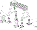
Fig. 1 is a schematic axial view of the present invention.
Fig. 2 is a front view of the present invention.
Fig. 3 is a schematic structural diagram in a split state of the present invention.
Fig. 4 is a schematic structural view of the travel driving mechanism of the present invention.
Fig. 5 is a schematic view of the present invention at a part enlarged in fig. 2.
Fig. 6 is a schematic view of the present invention at a part B in fig. 1.
Fig. 7 is a schematic structural view of the hydraulic jack-up mechanism of the present invention.
In the drawings, the corresponding relationship between the component names and the reference numbers is as follows:
1. a gantry crane main body; 2. a bearing connector; 201. a bearing; 202. limiting the jacks; 3. a travel drive mechanism; 301. a rectangular auxiliary slide cylinder; 302. a rectangular auxiliary slide bar; 303. a threaded post; 304. a rolling wheel; 305. a drive motor; 4. a limiting mechanism; 401. a limiting inserted rod; 402. pulling a rod; 403. an annular stop block; 404. a fixing plate; 5. a hydraulic jack-up mechanism; 501. a hydraulic cylinder; 502. a limiting sliding cylinder; 503. a support plate; 6. a horizontal adjustment member; 601. a threaded barrel.
Detailed Description
The embodiments of the present invention will be described in further detail with reference to the drawings and examples. The following examples are intended to illustrate the invention but are not intended to limit the scope of the invention.
In the description of the present invention, "a plurality" means two or more unless otherwise specified; the terms "upper", "lower", "left", "right", "inner", "outer", "front", "rear", "head", "tail", and the like, indicate orientations or positional relationships based on the orientations or positional relationships shown in the drawings, are only for convenience in describing and simplifying the description, and do not indicate or imply that the device or element referred to must have a particular orientation, be constructed in a particular orientation, and be operated, and thus, should not be construed as limiting the invention. Furthermore, the terms "first," "second," "third," and the like are used for descriptive purposes only and are not to be construed as indicating or implying relative importance.
In the description of the present invention, it is to be noted that, unless otherwise explicitly specified or limited, the terms "connected" and "connected" are to be interpreted broadly, e.g., as being fixed or detachable or integrally connected; can be mechanically or electrically connected; may be directly connected or indirectly connected through an intermediate. The specific meanings of the above terms in the present invention can be understood in specific cases to those skilled in the art.
Example (b):
as shown in figures 1 to 7:
the invention provides a hoisting device for transverse orbital transfer walking, which comprises: the gantry crane comprises a gantry crane main body 1, the lower ends of four support legs on the gantry crane main body 1 are respectively and rotatably connected with a bearing connecting piece 2, each bearing connecting piece 2 comprises a bearing 201 and limiting jacks 202, the upper end face of each bearing connecting piece 2 is provided with the bearing 201, the bearing connecting pieces 2 are rotatably connected with the lower ends of the upper support legs of the gantry crane main body 1 through the bearings 201, the edges of the upper end faces of the bearing connecting pieces 2 are provided with the four limiting jacks 202 in an annular array shape, and the included angle degree between every two adjacent limiting jacks 202 is ninety degrees; the bottom of each bearing connecting piece 2 is rotatably connected with a walking driving mechanism 3 through a rotating shaft, each walking driving mechanism 3 comprises a rectangular auxiliary sliding barrel 301, a rectangular auxiliary sliding rod 302, a threaded column 303, a rolling wheel 304 and a driving motor 305, the lower end inside the walking driving mechanism 3 is rotatably connected with the rolling wheel 304 through the rotating shaft, one side surface of the walking driving mechanism 3 is provided with the driving motor 305, the other end surface of the walking driving mechanism 3 is fixedly connected with the rectangular auxiliary sliding barrel 301, the rectangular auxiliary sliding rod 302 is slidably connected inside the rectangular auxiliary sliding barrel 301, the other end surface of the rectangular auxiliary sliding barrel 301 is provided with a strip-shaped sliding opening, the rear end of one side surface of the rectangular auxiliary sliding rod 302 is provided with the threaded column 303 which is slidably connected with the strip-shaped sliding opening on the rectangular auxiliary sliding barrel 301, and the outside; the traveling driving mechanism 3 is a rectangular shell structure, when the right end surface of a fastening hand wheel on the threaded column 303 is tightly contacted with the left end surface of the rectangular auxiliary sliding barrel 301, the rectangular auxiliary sliding rod 302 is in a fixed state in the rectangular auxiliary sliding barrel 301, so that the rectangular auxiliary sliding rod 302 can be effectively fixed when in use; the bottom parts of four legs on the gantry crane main body 1 are respectively provided with a limiting mechanism 4, each limiting mechanism 4 comprises a limiting inserted rod 401, a pulling rod 402, an annular limiting block 403 and a fixing plate 404, the bottom end surface of each limiting mechanism 4 is provided with the fixing plate 404 fixed on the top end surface of the lower part of the upper leg on the gantry crane main body 1, a limit inserted bar 401 which penetrates through the fixing plate 404 is connected in the limit mechanism 4 in a sliding way, an L-shaped sliding opening is arranged on the outer peripheral surface of the limit mechanism 4, a pulling bar 402 which is connected with the L-shaped sliding opening on the limit mechanism 4 in a sliding way is arranged in the middle of the front side of the outer peripheral surface of the limit inserted bar 401, an annular limiting block 403 is arranged at the upper part of the outer peripheral surface of the limiting inserted rod 401, an Contraband-shaped support plate which is rotatably connected with the upper end of the limiting inserted rod 401 is arranged on the upper end surface of the fixing plate 404, and a spring is sleeved between the upper end of the outer part of the limiting inserted link 401 and the opposite surface of the annular limiting block 403 and the Contraband-shaped support plate, the limit insertion rod 401 is more reliable when being inserted into the limit insertion hole 202 through the elasticity of the spring; the bottom end surfaces of the connecting rods of the support legs of the gantry crane main body 1 are respectively provided with a hydraulic jacking mechanism 5; the limiting mechanism 4 is of a circular cylindrical structure; the hydraulic jacking mechanism 5 is of a rectangular plate-shaped structure, the hydraulic jacking mechanism 5 comprises a hydraulic cylinder 501, limiting sliding barrels 502 and a supporting plate 503, the hydraulic cylinder 501 is installed at the center of the bottom end face of the hydraulic jacking mechanism 5, the supporting plate 503 is fixedly connected to the lower end of a telescopic rod of the hydraulic cylinder 501, the limiting sliding barrels 502 are fixedly connected to four included angles of the bottom end face of the hydraulic jacking mechanism 5, four reinforcing ribs are arranged between the outer peripheral face of each limiting sliding barrel 502 and the bottom end face of the hydraulic jacking mechanism 5 in an annular array manner, so that the limiting sliding barrels 502 have better supporting strength, limiting guide rods penetrating through the upper end face of the hydraulic jacking mechanism 5 are slidably connected inside each limiting sliding barrel 502, and a circular limiting block is arranged at the upper end of each limiting guide rod; four horizontal adjusting pieces 6 are arranged at the bottom of each hydraulic jacking mechanism 5, and when the bottom end face of a circular supporting disc at the lower end of each horizontal adjusting piece 6 is contacted with the ground, the rolling wheels 304 at the bottom of the walking driving mechanism 3 are separated from the rail.
Wherein, horizontal adjustment spare 6 includes a screw thread section of thick bamboo 601, horizontal adjustment spare 6 is cylindrical structure, and the outside screw thread that is equipped with of horizontal adjustment spare 6, horizontal adjustment spare 6 outside has the screw thread section of thick bamboo 601 of fixing in backup pad 503 up end contained angle department through threaded connection, and the 6 upper ends of horizontal adjustment spare are equipped with the rotation hand wheel, the rotation of 6 lower extremes of horizontal adjustment spare is connected with circular supporting disk, setting through horizontal adjustment spare 6, make to rotate horizontal adjustment spare 6 can be under the screw thread effect adjust the support height of the circular supporting disk of 6 lower extremes of horizontal adjustment spare, thereby can make backup pad 503 be in more steady state.
When the limiting mechanism 4 is in a limiting state, the lower end of the limiting insertion rod 401 is inserted into the limiting insertion hole 202 formed in the upper end face of the bearing connecting piece 2, so that the bearing connecting piece 2 can be effectively limited.
When in use: when the gantry crane is used after walking on the rail and needs to move to a nearby place, the telescopic rod of the hydraulic cylinder 501 in the hydraulic jacking mechanism 5 extends downwards to enable the support plate 503 to drive the horizontal adjusting piece 6 to move downwards, when the bottom end face of the circular support plate at the lower end of the horizontal adjusting piece 6 is contacted with the ground, the rolling wheel 304 at the bottom of the walking driving mechanism 3 is separated from the rail, so that the gantry crane main body 1 is jacked upwards, the pulling rod 402 on the limiting inserted rod 401 is pulled upwards, the pulling rod 402 is clamped on the upper part of an L-shaped sliding opening on the limiting mechanism 4, then the hand wheel fastened on the threaded column 303 is loosened, and then the rectangular auxiliary sliding rod 302 slides out of the rectangular auxiliary sliding barrel 301, then a hand wheel is fastened on the threaded column 303, the walking driving mechanism 3 is rotated by ninety degrees through the rectangular auxiliary sliding rod 302, the rolling direction of the rolling wheel 304 is changed, the limiting insertion rod 401 is inserted into the limiting insertion hole 202 formed in the bearing connecting piece 2, and then the walking driving mechanism 3 is rotated by ninety degrees, so that the gantry crane equipment can transversely walk on the track, the flexibility of the gantry crane equipment during walking is improved, and the gantry crane equipment transversely walks to a nearby site, so that a large amount of manpower and material resources are not required to be consumed, the moving efficiency is good, and the convenience of the gantry crane equipment during moving is improved;
through the setting of stop gear 4, insert spacing inserted bar 401 on bearing connecting piece 2 through after will rotation regulation for bearing connecting piece 2 can obtain effectual limiting displacement, thereby makes the running gear 3 of bearing connecting piece 2 bottom more stable when the walking, and then has improved the reliability of this gate-type hoisting equipment when the walking.
The embodiments of the present invention have been presented for purposes of illustration and description, and are not intended to be exhaustive or limited to the invention in the form disclosed. Many modifications and variations will be apparent to those of ordinary skill in the art. The embodiment was chosen and described in order to best explain the principles of the invention and the practical application, and to enable others of ordinary skill in the art to understand the invention for various embodiments with various modifications as are suited to the particular use contemplated.
Claims (8)
1. The utility model provides a hoisting equipment of horizontal orbital transfer walking which characterized in that: the gantry crane comprises a gantry crane main body (1), the lower ends of four support legs on the gantry crane main body (1) are respectively and rotatably connected with a bearing connecting piece (2), the bottom of each bearing connecting piece (2) is respectively and rotatably connected with a walking driving mechanism (3) through a rotating shaft, each walking driving mechanism (3) comprises a rectangular auxiliary sliding barrel (301), a rectangular auxiliary sliding rod (302), a threaded column (303), a rolling wheel (304) and a driving motor (305), the lower end inside the walking driving mechanism (3) is rotatably connected with the rolling wheel (304) through the rotating shaft, one side face of the walking driving mechanism (3) is provided with the driving motor (305), the other end face of the walking driving mechanism (3) is fixedly connected with the rectangular auxiliary sliding barrel (301), the rectangular auxiliary sliding barrel (301) is internally and slidably connected with the rectangular auxiliary sliding rod (302), and the other end face of the rectangular auxiliary sliding barrel (301) is, the rear end of one side face of the rectangular auxiliary sliding rod (302) is provided with a threaded column (303) which is in sliding connection with a strip-shaped sliding opening on the rectangular auxiliary sliding barrel (301), and the outside of the threaded column (303) is connected with a fastening hand wheel through threads; the walking driving mechanism (3) is of a rectangular shell structure; the bottom parts of four support legs on the gantry crane main body (1) are respectively provided with a limiting mechanism (4), and the bottom end surfaces of the support leg connecting rods of the gantry crane main body (1) are respectively provided with a hydraulic jacking mechanism (5); the limiting mechanism (4) is of a circular cylindrical structure; the hydraulic jacking mechanism (5) is of a rectangular plate-shaped structure; and four horizontal adjusting pieces (6) are arranged at the bottom of each hydraulic jacking mechanism (5).
2. The hoisting device for transverse orbital transfer walking according to claim 1, wherein: bearing connecting piece (2) include bearing (201) and spacing jack (202), bearing (201) are installed to bearing connecting piece (2) up end, and bearing connecting piece (2) rotate with portal crane main part (1) upper leg lower extreme through bearing (201) and be connected, bearing connecting piece (2) up end edge is the annular array form and has seted up four spacing jacks (202), and the contained angle degree of degrees is ninety degrees between per two adjacent spacing jacks (202).
3. The hoisting device for transverse orbital transfer walking according to claim 1, wherein: when the right end face of a fastening hand wheel on the threaded column (303) is tightly contacted with the left end face of the rectangular auxiliary sliding barrel (301), the rectangular auxiliary sliding rod (302) is in a fixed state in the rectangular auxiliary sliding barrel (301).
4. The hoisting device for transverse orbital transfer walking according to claim 1, wherein: the limiting mechanism (4) comprises a limiting inserted rod (401), a pulling rod (402), an annular limiting block (403) and a fixing plate (404), a fixing plate (404) fixed on the top end surface of the lower part of the upper leg of the gantry crane main body (1) is arranged on the bottom end surface of the limiting mechanism (4), and the inner part of the limiting mechanism (4) is connected with a limiting inserted rod (401) which penetrates through the fixing plate (404) in a sliding way, an L-shaped sliding opening is formed in the outer peripheral surface of the limiting mechanism (4), a pulling rod (402) which is connected with the L-shaped sliding opening on the limiting mechanism (4) in a sliding manner is arranged in the middle of the front side of the outer peripheral surface of the limiting insertion rod (401), an annular limiting block (403) is arranged at the upper part of the outer peripheral surface of the limiting inserted rod (401), an Contraband-shaped support plate which is rotatably connected with the upper end of the limiting inserted rod (401) is arranged on the upper end surface of the fixing plate (404), and the upper end of the outer part of the limiting inserted rod (401) is positioned between the opposite surfaces of the annular limiting block (403) and the Contraband-shaped support plate, and a spring is sleeved between the opposite surfaces.
5. The hoisting device for transverse orbital transfer walking according to claim 1, wherein: hydraulic jack-up mechanism (5) are including pneumatic cylinder (501), spacing slide cartridge (502) and backup pad (503), pneumatic cylinder (501) are installed to hydraulic jack-up mechanism (5) bottom face center part, and pneumatic cylinder (501) telescopic link lower extreme fixedly connected with backup pad (503), four contained angle departments of hydraulic jack-up mechanism (5) bottom face are spacing slide cartridge (502) of equal fixedly connected with, and all are the annular array form between every spacing slide cartridge (502) outer peripheral face and hydraulic jack-up mechanism (5) bottom face and are equipped with four strengthening ribs, every the inside equal sliding connection of spacing slide cartridge (502) has the spacing guide arm that runs through hydraulic jack-up mechanism (5) up end, and every spacing guide arm upper end all is equipped with circular stopper.
6. The hoisting device for transverse orbital transfer walking according to claim 1, wherein: horizontal adjustment spare (6) are including a screw thread section of thick bamboo (601), horizontal adjustment spare (6) are cylindrical structure, and horizontal adjustment spare (6) outside is equipped with the screw thread, horizontal adjustment spare (6) outside has screw thread section of thick bamboo (601) of fixing in backup pad (503) up end contained angle department through threaded connection, and horizontal adjustment spare (6) upper end is equipped with the rotation hand wheel, horizontal adjustment spare (6) lower extreme rotates and is connected with circular supporting disk.
7. The hoisting device for transverse orbital transfer walking according to claim 1, wherein: when the limiting mechanism (4) is in a limiting state, the lower end of the limiting insertion rod (401) is inserted into a limiting insertion hole (202) formed in the upper end face of the bearing connecting piece (2).
8. The hoisting device for transverse orbital transfer walking according to claim 1, wherein: when the bottom end face of the circular supporting disc at the lower end of the horizontal adjusting piece (6) is contacted with the ground, the rolling wheels (304) at the bottom of the walking driving mechanism (3) are separated from the track.
Priority Applications (1)
| Application Number | Priority Date | Filing Date | Title |
|---|---|---|---|
| CN202110036697.8A CN112723182B (en) | 2021-01-12 | 2021-01-12 | Hoisting equipment capable of walking in transverse rail transfer mode |
Applications Claiming Priority (1)
| Application Number | Priority Date | Filing Date | Title |
|---|---|---|---|
| CN202110036697.8A CN112723182B (en) | 2021-01-12 | 2021-01-12 | Hoisting equipment capable of walking in transverse rail transfer mode |
Publications (2)
| Publication Number | Publication Date |
|---|---|
| CN112723182A true CN112723182A (en) | 2021-04-30 |
| CN112723182B CN112723182B (en) | 2022-09-09 |
Family
ID=75590615
Family Applications (1)
| Application Number | Title | Priority Date | Filing Date |
|---|---|---|---|
| CN202110036697.8A Active CN112723182B (en) | 2021-01-12 | 2021-01-12 | Hoisting equipment capable of walking in transverse rail transfer mode |
Country Status (1)
| Country | Link |
|---|---|
| CN (1) | CN112723182B (en) |
Citations (10)
| Publication number | Priority date | Publication date | Assignee | Title |
|---|---|---|---|---|
| US4655104A (en) * | 1986-01-06 | 1987-04-07 | Ryeson Corporation | Adjustable torque wrench |
| CN2910883Y (en) * | 2006-04-05 | 2007-06-13 | 秦皇岛市北戴河通联路桥机械有限公司 | Direction changeable wheel rail type beam-lifting machine |
| CN102229402A (en) * | 2011-05-23 | 2011-11-02 | 三一集团有限公司 | Rubber-tired container gantry crane and steering device thereof |
| CN202704902U (en) * | 2012-06-27 | 2013-01-30 | 徐工集团工程机械股份有限公司 | Turning locking device for vehicle |
| CN204397755U (en) * | 2015-01-20 | 2015-06-17 | 林群富 | The adjustable antioverloading screwdriver of a kind of T-shaped load of telescopic handle |
| CN204778395U (en) * | 2015-07-10 | 2015-11-18 | 德马科起重机械有限公司 | Hoist walking switching -over device |
| CN205260609U (en) * | 2015-12-31 | 2016-05-25 | 湖南中铁五新重工有限公司 | Automatic bolt locking device of rotation mechanism and rotation mechanism |
| CN109231022A (en) * | 2018-11-26 | 2019-01-18 | 新乡市豫新起重机械有限公司 | A kind of four hydraulic cylinder height adjusting gantry crane of double supporting legs of rail-free |
| CN210214575U (en) * | 2019-06-05 | 2020-03-31 | 中交二公局第三工程有限公司 | Portal crane walking turns to device |
| CN210915222U (en) * | 2019-11-22 | 2020-07-03 | 山西工商学院 | Safety elevator for building construction |
-
2021
- 2021-01-12 CN CN202110036697.8A patent/CN112723182B/en active Active
Patent Citations (10)
| Publication number | Priority date | Publication date | Assignee | Title |
|---|---|---|---|---|
| US4655104A (en) * | 1986-01-06 | 1987-04-07 | Ryeson Corporation | Adjustable torque wrench |
| CN2910883Y (en) * | 2006-04-05 | 2007-06-13 | 秦皇岛市北戴河通联路桥机械有限公司 | Direction changeable wheel rail type beam-lifting machine |
| CN102229402A (en) * | 2011-05-23 | 2011-11-02 | 三一集团有限公司 | Rubber-tired container gantry crane and steering device thereof |
| CN202704902U (en) * | 2012-06-27 | 2013-01-30 | 徐工集团工程机械股份有限公司 | Turning locking device for vehicle |
| CN204397755U (en) * | 2015-01-20 | 2015-06-17 | 林群富 | The adjustable antioverloading screwdriver of a kind of T-shaped load of telescopic handle |
| CN204778395U (en) * | 2015-07-10 | 2015-11-18 | 德马科起重机械有限公司 | Hoist walking switching -over device |
| CN205260609U (en) * | 2015-12-31 | 2016-05-25 | 湖南中铁五新重工有限公司 | Automatic bolt locking device of rotation mechanism and rotation mechanism |
| CN109231022A (en) * | 2018-11-26 | 2019-01-18 | 新乡市豫新起重机械有限公司 | A kind of four hydraulic cylinder height adjusting gantry crane of double supporting legs of rail-free |
| CN210214575U (en) * | 2019-06-05 | 2020-03-31 | 中交二公局第三工程有限公司 | Portal crane walking turns to device |
| CN210915222U (en) * | 2019-11-22 | 2020-07-03 | 山西工商学院 | Safety elevator for building construction |
Also Published As
| Publication number | Publication date |
|---|---|
| CN112723182B (en) | 2022-09-09 |
Similar Documents
| Publication | Publication Date | Title |
|---|---|---|
| CN101712439B (en) | Crane transition auxiliary device, transport trailer and method for dismantling crane | |
| CN201339157Y (en) | Portable road paving device | |
| CN110629643B (en) | Floating robot | |
| CN101916974A (en) | Cable laying engineering truck | |
| CN201580913U (en) | Crane transition auxiliary device, transportation trailer | |
| CN112482784B (en) | Installation device applicable to assembly type building wall | |
| CN112723182B (en) | Hoisting equipment capable of walking in transverse rail transfer mode | |
| CN116253273B (en) | Fork truck with hosepipe receive and releases function | |
| CN112209264A (en) | Battery hoisting accessory is used in new energy automobile processing | |
| CN210313214U (en) | Telescopic structure of crane | |
| CN108867388A (en) | Multifunction working platform vehicle | |
| CN108483342B (en) | Carrier that supplementary installation of I-wire dish was dismantled | |
| CN209939952U (en) | Grain slag ship loader | |
| CN210915080U (en) | Rope arranging device for mining winch | |
| CN209143023U (en) | Mechanical automatic travelling device | |
| CN113148430A (en) | Underframe storage rack and underframe feeding device | |
| CN208649902U (en) | Multifunction working platform vehicle | |
| CN206051033U (en) | A kind of transfer platform and unloading system | |
| CN217200971U (en) | Lifting ship loader | |
| CN110668303A (en) | Tire type tunnel pipe rack conveying and erecting machine | |
| CN211056510U (en) | Tire type tunnel pipe rack conveying and erecting machine | |
| CN215924136U (en) | Swinging type lifting appliance assembly for truck power changing station | |
| CN116477470B (en) | Stable type inclined-pulling-preventing portal crane | |
| CN218538980U (en) | Gantry crane | |
| CN218754736U (en) | Crane winding drum assembling device |
Legal Events
| Date | Code | Title | Description |
|---|---|---|---|
| PB01 | Publication | ||
| PB01 | Publication | ||
| SE01 | Entry into force of request for substantive examination | ||
| SE01 | Entry into force of request for substantive examination | ||
| GR01 | Patent grant | ||
| GR01 | Patent grant |