CN112701959B - Solar energy comprehensive utilization photo-thermal hybrid power generation system - Google Patents
Solar energy comprehensive utilization photo-thermal hybrid power generation system Download PDFInfo
- Publication number
- CN112701959B CN112701959B CN202011529323.1A CN202011529323A CN112701959B CN 112701959 B CN112701959 B CN 112701959B CN 202011529323 A CN202011529323 A CN 202011529323A CN 112701959 B CN112701959 B CN 112701959B
- Authority
- CN
- China
- Prior art keywords
- matched
- groove
- block
- water
- heat dissipation
- Prior art date
- Legal status (The legal status is an assumption and is not a legal conclusion. Google has not performed a legal analysis and makes no representation as to the accuracy of the status listed.)
- Active
Links
- 238000010248 power generation Methods 0.000 title claims abstract description 43
- XLYOFNOQVPJJNP-UHFFFAOYSA-N water Substances O XLYOFNOQVPJJNP-UHFFFAOYSA-N 0.000 claims abstract description 145
- 238000010521 absorption reaction Methods 0.000 claims abstract description 8
- 230000017105 transposition Effects 0.000 claims abstract description 7
- 230000017525 heat dissipation Effects 0.000 claims description 42
- 238000002347 injection Methods 0.000 claims description 13
- 239000007924 injection Substances 0.000 claims description 13
- 238000000034 method Methods 0.000 claims description 7
- 239000011521 glass Substances 0.000 claims description 3
- 238000006243 chemical reaction Methods 0.000 abstract description 9
- 238000001816 cooling Methods 0.000 abstract description 4
- 239000002918 waste heat Substances 0.000 description 7
- 239000000243 solution Substances 0.000 description 3
- 238000010586 diagram Methods 0.000 description 2
- 241000112598 Pseudoblennius percoides Species 0.000 description 1
- 239000002826 coolant Substances 0.000 description 1
- 230000007547 defect Effects 0.000 description 1
- 230000002349 favourable effect Effects 0.000 description 1
- 238000002955 isolation Methods 0.000 description 1
- 238000012423 maintenance Methods 0.000 description 1
- 230000005855 radiation Effects 0.000 description 1
- 238000011084 recovery Methods 0.000 description 1
- 239000002699 waste material Substances 0.000 description 1
Images


Classifications
-
- H—ELECTRICITY
- H02—GENERATION; CONVERSION OR DISTRIBUTION OF ELECTRIC POWER
- H02N—ELECTRIC MACHINES NOT OTHERWISE PROVIDED FOR
- H02N11/00—Generators or motors not provided for elsewhere; Alleged perpetua mobilia obtained by electric or magnetic means
- H02N11/002—Generators
-
- F—MECHANICAL ENGINEERING; LIGHTING; HEATING; WEAPONS; BLASTING
- F24—HEATING; RANGES; VENTILATING
- F24S—SOLAR HEAT COLLECTORS; SOLAR HEAT SYSTEMS
- F24S30/00—Arrangements for moving or orienting solar heat collector modules
- F24S30/40—Arrangements for moving or orienting solar heat collector modules for rotary movement
- F24S30/42—Arrangements for moving or orienting solar heat collector modules for rotary movement with only one rotation axis
- F24S30/425—Horizontal axis
-
- H—ELECTRICITY
- H02—GENERATION; CONVERSION OR DISTRIBUTION OF ELECTRIC POWER
- H02S—GENERATION OF ELECTRIC POWER BY CONVERSION OF INFRARED RADIATION, VISIBLE LIGHT OR ULTRAVIOLET LIGHT, e.g. USING PHOTOVOLTAIC [PV] MODULES
- H02S20/00—Supporting structures for PV modules
- H02S20/30—Supporting structures being movable or adjustable, e.g. for angle adjustment
- H02S20/32—Supporting structures being movable or adjustable, e.g. for angle adjustment specially adapted for solar tracking
-
- H—ELECTRICITY
- H02—GENERATION; CONVERSION OR DISTRIBUTION OF ELECTRIC POWER
- H02S—GENERATION OF ELECTRIC POWER BY CONVERSION OF INFRARED RADIATION, VISIBLE LIGHT OR ULTRAVIOLET LIGHT, e.g. USING PHOTOVOLTAIC [PV] MODULES
- H02S30/00—Structural details of PV modules other than those related to light conversion
- H02S30/10—Frame structures
-
- H—ELECTRICITY
- H02—GENERATION; CONVERSION OR DISTRIBUTION OF ELECTRIC POWER
- H02S—GENERATION OF ELECTRIC POWER BY CONVERSION OF INFRARED RADIATION, VISIBLE LIGHT OR ULTRAVIOLET LIGHT, e.g. USING PHOTOVOLTAIC [PV] MODULES
- H02S40/00—Components or accessories in combination with PV modules, not provided for in groups H02S10/00 - H02S30/00
- H02S40/40—Thermal components
- H02S40/42—Cooling means
- H02S40/425—Cooling means using a gaseous or a liquid coolant, e.g. air flow ventilation, water circulation
-
- Y—GENERAL TAGGING OF NEW TECHNOLOGICAL DEVELOPMENTS; GENERAL TAGGING OF CROSS-SECTIONAL TECHNOLOGIES SPANNING OVER SEVERAL SECTIONS OF THE IPC; TECHNICAL SUBJECTS COVERED BY FORMER USPC CROSS-REFERENCE ART COLLECTIONS [XRACs] AND DIGESTS
- Y02—TECHNOLOGIES OR APPLICATIONS FOR MITIGATION OR ADAPTATION AGAINST CLIMATE CHANGE
- Y02E—REDUCTION OF GREENHOUSE GAS [GHG] EMISSIONS, RELATED TO ENERGY GENERATION, TRANSMISSION OR DISTRIBUTION
- Y02E10/00—Energy generation through renewable energy sources
- Y02E10/40—Solar thermal energy, e.g. solar towers
- Y02E10/47—Mountings or tracking
-
- Y—GENERAL TAGGING OF NEW TECHNOLOGICAL DEVELOPMENTS; GENERAL TAGGING OF CROSS-SECTIONAL TECHNOLOGIES SPANNING OVER SEVERAL SECTIONS OF THE IPC; TECHNICAL SUBJECTS COVERED BY FORMER USPC CROSS-REFERENCE ART COLLECTIONS [XRACs] AND DIGESTS
- Y02—TECHNOLOGIES OR APPLICATIONS FOR MITIGATION OR ADAPTATION AGAINST CLIMATE CHANGE
- Y02E—REDUCTION OF GREENHOUSE GAS [GHG] EMISSIONS, RELATED TO ENERGY GENERATION, TRANSMISSION OR DISTRIBUTION
- Y02E10/00—Energy generation through renewable energy sources
- Y02E10/50—Photovoltaic [PV] energy
Abstract
The invention discloses a solar energy comprehensive utilization photo-thermal hybrid power generation system, which comprises a photovoltaic cell arranged on a photovoltaic frame, a thermoelectric power generation component arranged on the photovoltaic frame and matched with a heat absorption plate, and transposition components positioned on two sides of the thermoelectric power generation component; according to the photovoltaic cell, the first water tank and the second water tank are arranged on two sides of the thermoelectric generation component, thermoelectric generation is carried out while the photovoltaic cell is cooled through water-cooling heat exchange of the thermoelectric generation component, redundant heat is stored through conversion of water in the first water tank and the second water tank, meanwhile the photovoltaic cell is adjusted towards the sun direction through the water capacity alternation of the first water tank and the second water tank and the cooperation of the supporting component, the maximum power generation efficiency of the photovoltaic cell is kept, the heat stored in the first water tank and the second water tank is used for generating power continuously under the condition without light, and the power generation hours are increased.
Description
Technical Field
The invention belongs to the technical field of comprehensive utilization of solar energy, and particularly relates to a solar energy comprehensive utilization photo-thermal hybrid power generation system.
Background
Among the solar energy utilization methods, solar photovoltaic power generation is one of the most common and studied methods. However, the solar photovoltaic power generation efficiency is low, generally only 10-20%, so that in the photoelectric conversion process of solar energy, on one hand, great waste of solar energy heat energy can be caused, and meanwhile, the temperature of the solar photovoltaic cell can also be increased due to the heat energy which is not converted into the electric energy. According to research, the conversion efficiency of the solar photovoltaic cell is reduced along with the rise of temperature, and the conversion efficiency of the solar photovoltaic cell is reduced by 3-6% due to waste heat generated during photoelectric conversion. Therefore, it is necessary to recover and utilize the waste heat. Conventional solutions mostly use forced convection or natural convection to absorb the waste heat, such as forced convection cooling systems using water or air. However, it should be noted that the temperature of the cooling medium rises after absorbing the heat of the solar photovoltaic cell panel during the flowing process, so that the temperature distribution of the solar photovoltaic cell panel is not uniform, and sometimes even a "hot spot" problem occurs, which is not favorable for improving the photoelectric conversion efficiency of the solar photovoltaic cell. Meanwhile, because the overall conversion efficiency of the existing photovoltaic cell is relatively low, the electric energy output of the traditional photovoltaic power generation system is difficult to meet the power consumption requirement of a user. Thermoelectric generation is as an effective mode of rationally utilizing low-grade energy such as waste heat, solar energy, geothermy to convert into electric energy, has simple structure, sturdy and durable, characteristics such as no moving parts and noise. In view of this, the radiation heat of the sun and the waste heat of the photovoltaic cell can be fully utilized to establish temperature difference at the two ends of the thermoelectric module, so that thermoelectric power generation is realized, and the overall electric energy output of the system is improved. However, since the efficiency of the thermoelectric power generation generally does not exceed 14%, it is necessary to recycle the secondary waste heat generated in the thermoelectric power generation process.
Based on the current situation and thought, a system combining a solar photovoltaic power generation component, a temperature difference power generation component and a heat utilization component for waste heat recovery is provided, namely, a solar comprehensive utilization system integrating photo-thermal hybrid power generation and heat utilization.
Disclosure of Invention
The invention provides a solar comprehensive utilization photo-thermal hybrid power generation system which is convenient to use, generates power for a short time and keeps high power generation efficiency, and aims to overcome the defects of the prior art.
In order to achieve the purpose, the invention adopts the following technical scheme: a solar energy comprehensive utilization photo-thermal hybrid power generation system comprises a photovoltaic frame, a photovoltaic cell arranged on the photovoltaic frame, a glass cover plate arranged on the photovoltaic cell, a heat absorption plate connected with the photovoltaic cell, a thermoelectric power generation component arranged on the heat absorption plate and transposition components positioned on two sides of the thermoelectric power generation component; the transposition component comprises a first water tank, a second water tank, a first water pump, a first water inlet tank, a second water pump, a second water inlet tank, a central fixed rotary rod, a central rotary groove, a central rotary shaft and a support component, wherein the first water tank is arranged on one side of the photovoltaic frame, the second water tank is arranged on the other side of the photovoltaic frame, the first water pump is arranged on the first water tank and connected with the thermoelectric generation component, the first water inlet tank is matched with the first water pump, the second water pump is arranged on the second water tank and matched with the thermoelectric generation component, the second water inlet tank is matched with the second water pump, the central fixed rotary rod is arranged at the lower part of the photovoltaic frame, the central rotary groove is arranged in the central fixed rotary rod, the central rotary shaft is matched with the central rotary groove, and the support component is arranged on the central rotary shaft; according to the photovoltaic cell, the first water tank and the second water tank are arranged on two sides of the thermoelectric generation component, thermoelectric generation is carried out while the photovoltaic cell is cooled through water-cooling heat exchange of the thermoelectric generation component, redundant heat is stored through conversion of water in the first water tank and the second water tank, meanwhile the photovoltaic cell is adjusted towards the sun direction through the water capacity alternation of the first water tank and the second water tank and the cooperation of the supporting component, the maximum power generation efficiency of the photovoltaic cell is kept, the heat stored in the first water tank and the second water tank is used for generating power continuously under the condition without light, and the power generation hours are increased.
The supporting component comprises supporting frames arranged at two sides of the central rotating shaft, matched fixed blocks arranged at two side edges of the photovoltaic frame, a first supporting plate arranged at one side of the supporting frame, a first limit rotating hole arranged on the first supporting plate, a second supporting plate arranged at the other side of the supporting frame, a second limit rotating hole arranged on the second supporting plate, a rotating ring plate arranged connected with the temperature difference power generation component, and a rack arranged on the rotating ring plate, the device comprises a gear matched with a rack, a fixed supporting plate arranged on a supporting frame, fixed supporting blocks arranged on the fixed supporting plate and positioned on two sides of the gear, moving clamping grooves arranged on two sides of a rotating ring plate, moving fixing grooves arranged on the moving clamping grooves, double-convex-block fixing pieces arranged on the fixed supporting blocks and matched with the moving fixing grooves, a rotating shaft arranged on the fixed supporting blocks and matched with the gear, and a fixing element arranged on the supporting frame and matched with a thermoelectric generation component; the utility model discloses a photovoltaic frame, including support assembly, photovoltaic frame, the rotatory rotation ring board of first spacing rotatory hole on the first backup pad and the rotatory hole of second spacing on the second backup pad, support assembly supports photovoltaic frame through support frame, prevent that the oblique rotation of photovoltaic frame from taking place for the off normal through the first spacing rotatory hole in the first backup pad and the spacing rotatory hole of second in the second backup pad from fixing to the rotatory ring board, and lead to contracting the rotatory stability of photovoltaic frame slope further, and carry out preliminary fixed and spacing to the rotatory ring board through the biconvex piece mounting, make the slope operation of photovoltaic frame further strengthen, cause the oblique rotation of photovoltaic frame to a great extent suddenly when preventing the water exchange of first water tank and second water tank, overall structure's stability has also obtained further enhancement simultaneously.
The fixing element comprises a first matching plate arranged on the support frame, a second matching plate arranged on the support frame, a first limiting groove arranged on two sides of one side of the bottom of the support frame, a first limiting column arranged in the first limiting groove, a first lug arranged on the first limiting column, a first groove arranged on the thermoelectric power generation component and matched with the first lug, a first fixing limiting groove arranged in the first limiting groove and matched with the first limiting column, a first limiting block arranged on the first limiting column and matched with the first fixing limiting groove, a first limiting spring arranged in the first fixing limiting groove and matched with the first limiting block, a second limiting groove arranged on two sides of one side of the bottom of the support frame, a second limiting column arranged in the second limiting groove, a second lug arranged on the second limiting column, a second groove arranged on the thermoelectric power generation component and matched with the second limiting column, a second fixing limiting groove arranged in the second limiting groove and matched with the second limiting column, The second limiting block is arranged on the second limiting column and matched with the second fixed limiting groove, and the second limiting spring is arranged in the second fixed limiting groove and matched with the second limiting block; the fixing element is used for fixedly supporting the two water tanks on the photovoltaic frame through the first matching plate and the second matching plate, and meanwhile, the first lug and the second lug on the two sides of the supporting frame are fixedly matched through the first groove on the first water tank and the second groove on the second water tank, so that the water part of the first water tank is injected into the second water tank after being alternately heated and heated by the thermoelectric generation part, the weight of the second water tank is larger than that of the first water tank, the first lug of the first supporting column on the supporting frame is not enough to fix the first water tank, after the first water tank is separated from the fixing part and limited part, the first water tank gradually moves upwards along with the increase of the weight of the second water tank as the operation action of the seesaw, the photovoltaic frame can be adjusted in the sun-facing direction along with the change of the weights of the two water tanks, and the maximum power generation efficiency of the photovoltaic cell is kept.
The temperature difference power generation component comprises a temperature difference power generation body connected with the heat absorption plate, a temperature difference power generation water tank which is provided with a plurality of temperature difference power generation bodies and is positioned in the temperature difference power generation bodies and matched with the first water inlet tank and the second water inlet tank, a cable protection block arranged on the photovoltaic frame, a cable which is arranged in the cable protection block and is connected with the photovoltaic cell, a first heat dissipation block arranged on the cable protection block, and a first heat dissipation cavity which is arranged on the first heat dissipation block and is matched with the cable protection block, the cable protection block is arranged on the cable protection block and is matched with the first heat dissipation cavity; the cable that the thermoelectric generation part is connected with photovoltaic cell is protected through setting up cable protection piece to cable protection piece dispels the heat through setting up first heat dissipation chamber and second heat dissipation chamber, be connected with first heat dissipation chamber through a plurality of first water injection grooves, make first heat dissipation chamber be full of cold water, and make the water in the first heat dissipation chamber take the heat of cable protection piece to the second through a plurality of second water injection grooves and dispel the heat the intracavity, will have thermal water injection thermoelectric generation basin end through the tye, make the cable effectively protect high temperature, and prevent outside morals and manners, increase life, reduce cost of maintenance.
According to the photovoltaic cell, the first water tank and the second water tank are arranged on two sides of the thermoelectric generation component, thermoelectric generation is carried out while the photovoltaic cell is cooled through water-cooling heat exchange of the thermoelectric generation component, redundant heat is stored through conversion of water in the first water tank and the second water tank, meanwhile the photovoltaic cell is adjusted towards the sun direction through the water capacity alternation of the first water tank and the second water tank and the cooperation of the supporting component, the maximum power generation efficiency of the photovoltaic cell is kept, the heat stored in the first water tank and the second water tank is used for generating power continuously under the condition without light, and the power generation hours are increased.
Drawings
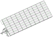
FIG. 1 is a schematic diagram of a plurality of parallel configurations of the present invention;
FIG. 2 is a schematic diagram of the present invention in isolation;
FIG. 3 is a left side view of the present invention;
FIG. 4 is a schematic cross-sectional view taken along line A-A of FIG. 3;
FIG. 5 is an enlarged schematic view at A in FIG. 4;
FIG. 6 is a schematic structural view of an indexing member according to the present invention;
FIG. 7 is a schematic view of a rotary ring plate according to the present invention;
FIG. 8 is a schematic structural view of a support assembly of the present invention;
FIG. 9 is a left side view of the support assembly of the present invention;
FIG. 10 is a cross-sectional view of FIG. 9 taken along line B-B;
fig. 11 is an enlarged schematic view at B in fig. 10.
Detailed Description
In order to make the technical solutions of the present invention better understood, the technical solutions in the embodiments of the present invention will be clearly and completely described below with reference to the drawings in the embodiments of the present invention.
As shown in fig. 1-11, a solar energy comprehensive utilization photo-thermal hybrid power generation system comprises a photovoltaic frame 1, a photovoltaic cell 2 arranged on the photovoltaic frame 1, a glass cover plate 3 arranged on the photovoltaic cell 2, a heat absorbing plate 4 connected with the photovoltaic cell 2, a thermoelectric power generation component 5 arranged on the heat absorbing plate 4, and transposition components 6 positioned at two sides of the thermoelectric power generation component 5; the transposition component 6 comprises a first water tank 7, a second water tank 8, a first water pump 9, a first water inlet tank 10, a second water pump 11, a second water inlet tank 12, a central fixed rotary rod 13, a central rotary tank 14, a central rotary shaft 15 and a support component 16; the photovoltaic module is characterized in that the first water tank 7 is arranged on one side of the photovoltaic frame 1, the second water tank 8 is arranged on the other side of the photovoltaic frame 1, the first water pump 9 is arranged on the first water tank 7 and connected with the thermoelectric generation component 5, the first water inlet tank 10 is connected with the first water pump 9, the second water pump 11 is arranged on the second water tank 8 and connected with the thermoelectric generation component 5, the second water inlet tank 12 is connected with the second water, the central fixed rotating rod 13 is arranged on the lower portion of the photovoltaic frame 1, the central rotating tank 14 is arranged in the central fixed rotating rod 13, the central rotating shaft 15 is in rotating fit with the central rotating tank 14, and the supporting component 16 is arranged on the central rotating shaft 15.
The supporting component 16 comprises a supporting frame 17, a matching fixed block 18, a first supporting plate 19, a first limiting rotation hole 20, a second supporting plate 21, a second limiting rotation hole 22, a rotating ring plate 23, a rack 24, a gear 25, a fixed supporting plate 26, a fixed supporting block 27, a moving clamping groove 28, a moving fixing groove 29, a double-convex-block fixing piece 30, a rotating shaft 31 and a fixing element 32; the supporting frame 17 is arranged on two sides of the central rotating shaft 15, the matching fixed blocks 18 are arranged on two sides of the photovoltaic frame 1, the first supporting plate 19 is arranged on one side of the supporting frame 17, the first limit rotating hole 20 is arranged on the first supporting plate 19, the second supporting plate 21 is arranged on the other side of the supporting frame 17, the second limit rotating hole 22 is arranged on the second supporting plate 21, the rotating ring plate 23 is arranged and connected with the thermoelectric generation component 5, the rack 24 is arranged on the rotating ring plate 23, the gear 25 is rotatably engaged with the rack 24, the fixed supporting plate 26 is arranged on the supporting frame 17, the fixed supporting block 27 is arranged on the fixed supporting plate 26 and is arranged on two sides of the gear 25, the moving clamping groove 28 is arranged on two sides of the rotating ring plate 23, the moving fixed groove 29 is arranged on the moving clamping groove 28, the double-convex block fixing piece 30 is arranged on the fixed supporting block 27 and is movably and fixedly matched with the moving fixed groove 29, the rotating shaft 31 is arranged on the fixed supporting block 27 and is rotatably matched with the gear 25, the fixing member 32 is provided on the support frame 17 in fixed engagement with the thermoelectric generation component 5.
The fixing element 32 comprises a first matching plate 33, a second matching plate 34, a first limiting groove 35, a first limiting column 36, a first bump 37, a first groove 38, a first fixing limiting groove 39, a first limiting block 40, a first limiting spring 41, a second limiting groove 42, a second limiting column 43, a second bump 44, a second groove 45, a second fixing limiting groove 46, a second limiting block 47 and a second limiting spring 48; the first fitting plate 33 is provided on the support frame 17, the second fitting plate 34 is provided on the support frame 17, the first limit groove 35 is provided on both sides of the bottom side of the support frame 17, the first limit post 36 is provided in the first limit groove 35, the first projection 37 is provided on the first limit post 36, the first groove 38 is provided on the thermoelectric generation element 5 to be movably and fixedly fitted with the first projection 37, the first fixed limit groove 39 is provided in the first limit groove 35 to be slidably fitted with the first limit post 36, the first limit block 40 is provided on the first limit post 36 to be slidably fitted with the first fixed limit groove 39, the first limit spring 41 is provided in the first fixed limit groove 39 to be elastically fitted with the first limit block 40, the second limit groove 42 is provided on both sides of the bottom side of the support frame 17, the second limit post 43 is provided in the second limit groove 42, the second projection 44 is provided on the second limit post 43, the second groove 45 is provided on the thermoelectric generation element 5 to be fixedly fitted with the second projection 44, the second fixed limiting groove 46 is arranged in the second limiting groove 42 and is in sliding fit with the second limiting post 43, the second limiting block 47 is arranged on the second limiting post 43 and is in sliding fit with the second fixed limiting groove 46, and the second limiting spring 48 is arranged in the second fixed limiting groove 46 and is in elastic fit with the second limiting block 47.
The thermoelectric generation component 5 comprises a thermoelectric generation body 49, a thermoelectric generation water tank 50, a cable protection block 51, a cable 52, a first heat dissipation block 53, a first heat dissipation cavity 54, a second heat dissipation block 55, a second heat dissipation cavity 56, a first water injection tank 57, a second water injection tank 58 and a water flowing tank 59; the thermoelectric generation body 49 is connected with the heat absorbing plate 4, a plurality of thermoelectric generation water grooves 50 are arranged in the thermoelectric generation body 49 and connected with the first water inlet groove 10 and the second water inlet groove 12, the cable protection block 51 is arranged on the photovoltaic frame 1, the cable 52 is arranged in the cable protection block 51 and connected with the photovoltaic cell 2, the first heat dissipation block 53 is arranged on the cable protection block 51, the first heat dissipation cavity 54 is arranged on the first heat dissipation block 53 and connected with the cable protection block 51, the second heat dissipation block 55 is connected with the first heat dissipation cavity, the second heat dissipation cavity 56 is arranged on the cable protection block 51, the second heat dissipation block 55 is connected with the first heat dissipation cavity 54, a plurality of first water injection grooves 57 are arranged on the thermoelectric generation water grooves 50 and connected with the first heat dissipation cavity 54, a plurality of second water injection grooves 58 are arranged on the first heat dissipation block 53 and connected with the first heat dissipation cavity 54 and the second heat dissipation cavity 56, and a plurality of water injection grooves 59 are arranged on the thermoelectric generation body 49 and connected with the second heat dissipation block 55.
The specific working process is as follows:
the sun rises, the photovoltaic cell 2 on the photovoltaic frame 1 operates to generate power and starts to rise temperature, cold water in the first water tank 7 is injected into the thermoelectric generation body 49 through the first water pump 9, the thermoelectric generation water tank 50 dissipates heat of the photovoltaic cell 2, meanwhile, the thermoelectric generation body 49 performs thermoelectric generation by utilizing the thermoelectric generation water tank 50, the cable protection block 51 is connected with the heat absorption plate 4, cold water is injected into the first heat dissipation cavity 54 through the first water injection tank 57, the cold water circulates for a circle and flows into the second heat dissipation cavity 56 through the second water injection tank 58, finally, the cold water enters the tail end of the thermoelectric generation water tank 50 through the water flowing tank 59 and flows into the second water tank 8, hot water in the second water tank 8 is gradually increased through slow operation of the first water pump 9, so that the cold water in the first water tank 7 is gradually reduced under the rotation matching of the central fixing rotary rod 13 of the photovoltaic frame 1 and the central rotary shaft 15 through the central rotary groove 14, the first groove 38 on the first water tank 7 is released from the first protrusion 37 on the first limit column 36, the photovoltaic frame 1 at one end of the second water tank 8 is gradually inclined downwards, the second groove 45 on the second water tank 8 is fixedly matched with the second protrusion 44 on the second limit column 43, so that the second water tank 8 of the photovoltaic cell 2 is fixed on the support frame 17 after the second water tank is inclined, the rotating ring plate 23 arranged on the thermoelectric generation component 5 gradually moves through the matching of the gear 25 and the rack 24 while the photovoltaic cell 2 rotates obliquely, and the double-protrusion fixing piece 30 fixes the moving fixing groove 29 in the moving clamping groove 28 of the rotating ring plate 23. The integral fixing takes place with a fixed fit of the fixing element 32.
After the sun falls, the second water pump 11 connected to the second water tank 8 is operated to introduce the hot water in the second water tank 8 into the thermoelectric generation part 5, and thermoelectric generation is performed, and finally the hot water is poured into the first water tank in the same manner as the above operation, but in the opposite direction.
While there have been shown and described what are at present considered the fundamental principles and essential features of the invention and its advantages, it will be apparent to those skilled in the art that the invention is not limited to the details of the foregoing exemplary embodiments, but is capable of other specific forms without departing from the spirit or essential characteristics thereof. The present embodiments are therefore to be considered in all respects as illustrative and not restrictive, the scope of the invention being indicated by the appended claims rather than by the foregoing description, and all changes which come within the meaning and range of equivalency of the claims are therefore intended to be embraced therein. Any reference sign in a claim should not be construed as limiting the claim concerned.
Furthermore, it should be understood that although the present description refers to embodiments, not every embodiment may contain only a single embodiment, and such description is for clarity only, and those skilled in the art should integrate the description, and the embodiments may be combined as appropriate to form other embodiments understood by those skilled in the art.
Claims (1)
1. A solar energy comprehensive utilization photo-thermal hybrid power generation system comprises a photovoltaic frame (1), a photovoltaic cell (2) arranged on the photovoltaic frame (1), a glass cover plate (3) arranged on the photovoltaic cell (2), a heat absorption plate (4) connected with the photovoltaic cell (2), a thermoelectric power generation component (5) arranged on the heat absorption plate (4) and transposition components (6) positioned on two sides of the thermoelectric power generation component (5); the method is characterized in that: the transposition component (6) comprises a first water tank (7) arranged on one side of the photovoltaic frame (1), a second water tank (8) arranged on the other side of the photovoltaic frame (1), a first water pump (9) arranged on the first water tank (7) and connected with the temperature difference power generation component (5), a first water inlet tank (10) matched with the first water pump (9), a second water pump (11) arranged on the second water tank (8) and matched with the temperature difference power generation component (5), a second water inlet tank (12) matched with the second water pump (11), a central fixed rotary rod (13) arranged at the lower part of the photovoltaic frame (1), a central rotary groove (14) arranged in the central fixed rotary rod (13), a central rotary shaft (15) matched with the central rotary groove (14), and a support component (16) arranged on the central rotary shaft (15);
the supporting assembly (16) comprises supporting frames (17) arranged on two sides of a central rotating shaft (15), matching fixed blocks (18) arranged on two side edges of the photovoltaic frame (1), first supporting plates (19) arranged on one sides of the supporting frames (17), first limiting rotating holes (20) arranged on the first supporting plates (19), second supporting plates (21) arranged on the other sides of the supporting frames (17), second limiting rotating holes (22) arranged on the second supporting plates (21), rotating ring plates (23) arranged on the temperature difference generating parts (5), racks (24) arranged on the rotating ring plates (23), gears (25) matched with the racks (24), fixed supporting plates (26) arranged on the supporting frames (17), fixed supporting blocks (27) arranged on the fixed supporting plates (26) and positioned on two sides of the gears (25), and moving clamping grooves (28) arranged on two sides of the rotating ring plates (23), A movable fixing groove (29) arranged on the movable clamping groove (28), a double-convex block fixing piece (30) arranged on the fixed supporting block (27) and matched with the movable fixing groove (29), a rotating shaft (31) arranged on the fixed supporting block (27) and matched with the gear (25), and a fixing element (32) arranged on the supporting frame (17) and matched with the thermoelectric generation component (5);
the fixing element (32) comprises a first matching plate (33) arranged on the supporting frame (17), a second matching plate (34) arranged on the supporting frame (17), a first limiting groove (35) arranged on two sides of the bottom of the supporting frame (17), a first limiting column (36) arranged in the first limiting groove (35), a first convex block (37) arranged on the first limiting column (36), a first groove (38) arranged on the thermoelectric generation component (5) and matched with the first convex block (37), a first fixed limiting groove (39) arranged in the first limiting groove (35) and matched with the first limiting column (36), a first limiting block (40) arranged on the first limiting column (36) and matched with the first fixed limiting groove (39), a first limiting spring (41) arranged in the first fixed limiting groove (39) and matched with the first limiting block (40), and second limiting grooves (42) arranged on two sides of the bottom of the supporting frame (17), A second limit column (43) arranged in the second limit groove (42), a second lug (44) arranged on the second limit column (43), a second groove (45) arranged on the thermoelectric generation component (5) and matched with the second lug (44), a second fixed limit groove (46) arranged in the second limit groove (42) and matched with the second limit column (43), a second limit block (47) arranged on the second limit column (43) and matched with the second fixed limit groove (46), and a second limit spring (48) arranged in the second fixed limit groove (46) and matched with the second limit block (47);
the thermoelectric generation component (5) comprises a thermoelectric generation body (49) connected with the heat absorption plate (4), a plurality of thermoelectric generation water grooves (50) which are positioned in the thermoelectric generation body (49) and matched with the first water inlet groove (10) and the second water inlet groove (12), a cable protection block (51) arranged on the photovoltaic frame (1), a cable (52) arranged in the cable protection block (51) and connected with the photovoltaic cell (2), a first heat dissipation block (53) arranged on the cable protection block (51), a first heat dissipation cavity (54) arranged between the first heat dissipation block (53) and the cable protection block (51), a second heat dissipation block (55) matched with the first heat dissipation cavity (54), a second heat dissipation block (55) arranged on the cable protection block (51), a second heat dissipation cavity (56) matched with the first heat dissipation cavity (54), and a plurality of first water injection grooves (57) and a plurality of water injection grooves (57) arranged on the thermoelectric generation water grooves (50) and connected with the first heat dissipation cavity (54), The heat dissipation device is provided with a plurality of second water injection grooves (58) which are positioned on the first heat dissipation block (53) and connected with the first heat dissipation cavity (54) and the second heat dissipation cavity (56), and a plurality of water flowing grooves (59) which are positioned on the thermoelectric generator (49) and connected with the second heat dissipation block (55).
Priority Applications (1)
| Application Number | Priority Date | Filing Date | Title |
|---|---|---|---|
| CN202011529323.1A CN112701959B (en) | 2020-12-22 | 2020-12-22 | Solar energy comprehensive utilization photo-thermal hybrid power generation system |
Applications Claiming Priority (1)
| Application Number | Priority Date | Filing Date | Title |
|---|---|---|---|
| CN202011529323.1A CN112701959B (en) | 2020-12-22 | 2020-12-22 | Solar energy comprehensive utilization photo-thermal hybrid power generation system |
Publications (2)
| Publication Number | Publication Date |
|---|---|
| CN112701959A CN112701959A (en) | 2021-04-23 |
| CN112701959B true CN112701959B (en) | 2022-01-28 |
Family
ID=75510493
Family Applications (1)
| Application Number | Title | Priority Date | Filing Date |
|---|---|---|---|
| CN202011529323.1A Active CN112701959B (en) | 2020-12-22 | 2020-12-22 | Solar energy comprehensive utilization photo-thermal hybrid power generation system |
Country Status (1)
| Country | Link |
|---|---|
| CN (1) | CN112701959B (en) |
Family Cites Families (4)
| Publication number | Priority date | Publication date | Assignee | Title |
|---|---|---|---|---|
| KR20120065733A (en) * | 2010-12-13 | 2012-06-21 | 서상길 | Sun location tracking type solar generation apparatus |
| CN103166505A (en) * | 2011-12-11 | 2013-06-19 | 西安大昱光电科技有限公司 | Solar energy power generating device |
| CN105429574B (en) * | 2015-12-23 | 2017-10-24 | 广东亿腾新能源有限公司 | One kind self-regulation photovoltaic module support and its adjusting method |
| CN108258993A (en) * | 2018-03-20 | 2018-07-06 | 天津博帆科技发展有限公司 | It is a kind of can automatic sun-tracking photovoltaic power generation apparatus |
-
2020
- 2020-12-22 CN CN202011529323.1A patent/CN112701959B/en active Active
Also Published As
| Publication number | Publication date |
|---|---|
| CN112701959A (en) | 2021-04-23 |
Similar Documents
| Publication | Publication Date | Title |
|---|---|---|
| RU2382953C1 (en) | Combined solar power plant | |
| KR102026003B1 (en) | Combined Concentrator Photovoltaic Equipment | |
| CN102162433A (en) | Solar heat-storage power generating method with gas afterburning function and device thereof | |
| CN202065137U (en) | Solar thermal storage power generation device with gas complementary combustion | |
| CN112701959B (en) | Solar energy comprehensive utilization photo-thermal hybrid power generation system | |
| CN105450173A (en) | Heat pipe type concentrating photovoltaic cooling heat-collecting apparatus | |
| CN201616447U (en) | Solar electricity-heating integrated component | |
| CN204928746U (en) | Spotlight solar electric system with heat abstractor | |
| CN214499328U (en) | Power generation system | |
| CN108615844A (en) | A kind of radiator of the increasing hot and cold air flowing of new energy battery pack | |
| CN209857411U (en) | Cooling device for geothermal energy | |
| CN201766530U (en) | Focusing water cooling solar energy generation device | |
| CN206743159U (en) | A kind of photovoltaic solar cells board mounting stand | |
| CN102104345A (en) | Light-concentrating crystalline silicon solar battery component | |
| CN218771887U (en) | Support for photovoltaic system construction | |
| CN212625901U (en) | New energy battery heat dissipation shock mounting | |
| CN202307983U (en) | Solar power generation device | |
| CN202930416U (en) | Solar high-power light-focusing heat-collecting integral cell unit module | |
| CN112554979B (en) | Photovoltaic and photo-thermal coupling power generation system | |
| CN213331418U (en) | Photovoltaic power generation and heat energy power generation integrated power generation device | |
| CN215528955U (en) | Solar energy component convenient to assemble | |
| CN220421753U (en) | Multiunit but self-cleaning photovoltaic module device of fast-assembling | |
| CN212627772U (en) | Solar panel angle adjusting device | |
| CN112201805B (en) | Frame type low-temperature fuel cell device | |
| CN218296262U (en) | Trough type solar heat collector with power generation function |
Legal Events
| Date | Code | Title | Description |
|---|---|---|---|
| PB01 | Publication | ||
| PB01 | Publication | ||
| SE01 | Entry into force of request for substantive examination | ||
| SE01 | Entry into force of request for substantive examination | ||
| GR01 | Patent grant | ||
| GR01 | Patent grant |