CN112697432A - Device for detecting quality of bearing - Google Patents
Device for detecting quality of bearing Download PDFInfo
- Publication number
- CN112697432A CN112697432A CN202110050398.XA CN202110050398A CN112697432A CN 112697432 A CN112697432 A CN 112697432A CN 202110050398 A CN202110050398 A CN 202110050398A CN 112697432 A CN112697432 A CN 112697432A
- Authority
- CN
- China
- Prior art keywords
- plate
- motor
- cavity
- center
- fixedly arranged
- Prior art date
- Legal status (The legal status is an assumption and is not a legal conclusion. Google has not performed a legal analysis and makes no representation as to the accuracy of the status listed.)
- Granted
Links
Images


Classifications
-
- G—PHYSICS
- G01—MEASURING; TESTING
- G01M—TESTING STATIC OR DYNAMIC BALANCE OF MACHINES OR STRUCTURES; TESTING OF STRUCTURES OR APPARATUS, NOT OTHERWISE PROVIDED FOR
- G01M13/00—Testing of machine parts
- G01M13/04—Bearings
Abstract
The invention discloses a device for detecting the quality of a bearing, which comprises a rack, wherein a storage cavity with an upward opening is arranged in the rack, the bearing is arranged in the storage cavity in a sliding manner, a push plate is arranged at the left end of the bearing in a sliding manner, a lead screw is fixedly arranged at the left end of the push plate, a meshing nut is arranged on the lead screw in a threaded manner, the lower end of the storage cavity is communicated with a movable cavity, and two supporting toothed plates are arranged at the upper end of the movable cavity in a sliding manner.
Description
Technical Field
The invention relates to the field of bearing correlation, in particular to a device for detecting the quality of a bearing.
Background
When people use the bearing at present, the structure inside the bearing can not be directly tested, so that the bearing is damaged due to the fact that people use the bearing for a short time, the use of a machine is influenced, more installation time is wasted, and the working efficiency is low.
Disclosure of Invention
In order to solve the problems, the embodiment designs a device for detecting the quality of a bearing, the device for detecting the quality of the bearing comprises a frame, a storage cavity with an upward opening is arranged in the frame, the storage cavity is internally provided with the bearing in a sliding manner, the left end of the bearing is provided with a push plate in a sliding manner, the left end of the push plate is fixedly provided with a lead screw, a meshing nut is arranged on the lead screw in a threaded manner, the lower end of the storage cavity is communicated with a movable cavity, the upper end of the movable cavity is provided with two supporting toothed plates in a sliding manner, the two supporting toothed plates abut against the lower end surface of the bearing, the two supporting toothed plates are symmetrically distributed in a front-back manner by taking the center of the movable cavity as an abutting center, the front end and the rear end of the movable cavity are communicated with two sliding cavities, the two sliding cavities are symmetrically distributed in a front, a reset spring is fixedly arranged at the upper end of the movable toothed plate, the upper end of the reset spring is fixedly connected to the inner wall of the upper side of the sliding cavity, a rolling gear is meshed with one end of the movable toothed plate far away from the center of the movable cavity, a toothed mandrel is fixedly arranged at one end of the rolling gear close to the center of the movable cavity, a driving sprocket is fixedly arranged at one end of the toothed mandrel close to the center of the movable cavity, a driven sprocket is rotatably arranged at the upper side of the driving sprocket, a chain is connected between the driven sprocket and the driving sprocket, a connecting rod is arranged at one end of the driven sprocket close to the center of the movable cavity, a rotating tooth is fixedly arranged at one end of the connecting rod close to the center of the movable cavity, the upper end of the rotating tooth is meshed with the supporting toothed plate, a detection cavity is communicated with the right end of the, the left end and the right end of the rotating plate are respectively provided with two placing cavities with upward openings, the upper side of the placing cavity is provided with a detection plate in a sliding manner, the upper end of the detection plate is fixedly provided with a limiting block, the left side and the right side of the detection plate can be abutted against the lower end of the movable toothed plate and can move upwards along with the detection plate, the upper end of the detection cavity is provided with a rotating plate in a sliding manner, the lower end of the rotating plate is fixedly provided with a fixed block, the lower end of the fixed block is fixedly provided with a pressure block, the pressure block is positioned on the upper side of the detection plate on the right side, a detection groove with a downward opening is arranged in the pressure block, the left end and the right end of the detection groove are fixedly provided with two pressure detectors, the two pressure detectors are distributed in a bilateral symmetry, two sliding racks are arranged at the front end and the rear end of the motor block in a sliding mode, the two sliding racks are distributed in a front-rear mirror mode by taking the center of the motor block as a mirror center, a limiting box is fixedly arranged at one end, far away from the center of the motor block, of each sliding rack, a clamping cavity with an opening close to the center of the motor block is arranged in the limiting box, a touch panel is arranged in the clamping cavity in a sliding mode, a sliding rod is fixedly arranged at one end, far away from the center of the motor block, of each touch panel, one end is fixedly connected to the inner wall of the clamping cavity, two fan-shaped wheels are respectively meshed at the upper end and the lower end of each sliding rod, the two fan-shaped wheels are distributed in an up-down symmetrical mode by taking the sliding rods as symmetrical centers, and a swinging rod is fixedly arranged at one end, far away from the centers of the, the swing rod is rotatably connected in the clamping cavity, one end of the swing rod, which is far away from the sector wheel, is hinged with a sliding plate, a through groove which is communicated with the front and the back is arranged in the swing rod, the sliding plate is slidably connected in the through groove, the clamping plate is fixedly arranged on the sliding plate, when the device starts to work, a bearing to be detected is placed in the storage cavity, the bearing in the storage cavity is pushed to the upper end of the supporting toothed plate through the push plate, the supporting toothed plate is driven to contract in the sliding cavity through gear and rack transmission, the detection plate is driven to move upwards through a hydraulic device, the limiting block extends into the bearing for limiting, the detected bearing is placed on the detection plate, the detected bearing is moved to the lower side of the pressure block through rotation of the rotating plate, and the pressure block is driven to move downwards through screw rod transmission, and then contradict on the bearing, and then realize the pressure detection to the bearing, and then drive through the motor the rotor plate rotates, and then drives the slip rack is located the left and right sides of bearing, and then drive through rack and pinion transmission both ends stretch into to the centre gripping intracavity, and then drive the grip block presss from both sides tightly the left and right sides of bearing, and then the realization is right the rotation of bearing detects.
Preferably, a power motor is fixedly arranged in the rack, a transmission shaft is arranged at the left end of the power motor in a power mode, rotating teeth are fixedly arranged at the left end of the transmission shaft, and the upper ends of the rotating teeth are meshed with the meshing screw caps.
Preferably, the power shaft is arranged at the lower end of the power motor in a power mode, a driving belt wheel is fixedly arranged at the lower end of the power shaft, a driven belt wheel is arranged on the right side of the driving belt wheel in a rotating mode, a belt is connected between the driven belt wheel and the driving belt wheel, a rotating rod is fixedly arranged at the upper end of the driven belt wheel, and the upper end of the rotating rod is fixedly connected to the lower end face of the rotating plate.
Preferably, a motor shaft is arranged at the right end of the power motor in a power mode, a driving bevel gear is fixedly arranged at the right end of the motor shaft, a driven bevel gear is arranged at the upper end of the driving bevel gear in a meshed mode, a connecting shaft is fixedly arranged at the upper end of the driven bevel gear, a driving wheel is fixedly arranged at the upper end of the connecting shaft, a driven wheel is rotatably arranged on the right side of the driving wheel, a transmission belt is arranged between the driven wheel and the driving wheel in a connected mode, a threaded sleeve is fixedly arranged on the driven wheel, a screw rod is arranged on the lower.
Preferably, a gear motor is fixedly arranged in the motor block, a gear shaft is dynamically arranged at the lower end of the gear motor, a meshing gear is fixedly arranged at the lower end of the gear shaft, and the left end and the right end of the meshing gear are meshed and connected with the sliding rack.
Preferably, the lower end of the gear motor is provided with a rotating shaft, the lower end of the rotating shaft is fixedly provided with a friction block, the screw is internally fixedly provided with a rotating motor, and the lower end of the rotating motor is connected to the upper end face of the rotating plate through power.
Preferably, the lower end of the detection plate is fixedly provided with a hydraulic telescopic rod, and the lower end of the hydraulic telescopic rod is fixedly connected to the inner wall of the lower side of the placing cavity.
The invention has the beneficial effects that: the invention can complete the pressure detection of the ball bearing and the rotation condition detection after bearing the pressure, thereby avoiding the influence of the bearing problem on the working efficiency when people use the ball bearing, and reducing the waste of more time and more manpower and material resources when people detect the bearing.
Drawings
In order to more clearly illustrate the embodiments of the invention or the technical solutions in the prior art, the drawings used in the description of the embodiments or the prior art will be briefly described below, and it is obvious that the drawings in the following description are only some embodiments of the invention, and it is obvious for those skilled in the art that other drawings can be obtained based on these drawings without creative efforts.
The invention is further illustrated with reference to the following figures and examples.
Fig. 1 is a schematic overall structure diagram of a device for detecting bearing quality according to the invention.
Fig. 2 is an enlarged schematic view of a in fig. 1.
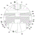
Fig. 3 is a schematic diagram of the structure B-B in fig. 2.
Detailed Description
The invention will now be described in detail with reference to fig. 1-3, wherein for ease of description the orientations described hereinafter are now defined as follows: the up, down, left, right, and front-back directions described below correspond to the up, down, left, right, and front-back directions in the projection relationship of fig. 1 itself.
The device for detecting the quality of the bearing comprises a frame 11, wherein a storage cavity 37 with an upward opening is arranged in the frame 11, a bearing 36 is arranged in the storage cavity 37 in a sliding manner, a push plate 74 is arranged at the left end of the bearing 36 in a sliding manner, a lead screw 35 is fixedly arranged at the left end of the push plate 74, a meshing nut 33 is arranged on the lead screw 35 in a threaded manner, a movable cavity 26 is arranged at the lower end of the storage cavity 37 in a communicating manner, two supporting toothed plates 43 are arranged at the upper end of the movable cavity 26 in a sliding manner, the two supporting toothed plates 43 abut against the lower end surface of the bearing 36, the two supporting toothed plates 43 are symmetrically distributed in a front-back manner by taking the center of the movable cavity 26 as an abutting center, the two sliding cavities 40 are arranged at the front end and the back end of the movable cavity 26 in a communicating manner, the two sliding cavities 40 are symmetrically distributed in a front, the upper end of the movable toothed plate 29 is fixedly provided with a return spring 30, the upper end of the return spring 30 is fixedly connected to the inner wall of the upper side of the sliding cavity 40, one end of the movable toothed plate 29, which is far away from the center of the movable cavity 26, is engaged with a rolling gear 28, one end of the rolling gear 28, which is close to the center of the movable cavity 26, is fixedly provided with a tooth spindle 23, one end of the tooth spindle 23, which is close to the center of the movable cavity 26, is fixedly provided with a driving sprocket 22, the upper side of the driving sprocket 22 is rotatably provided with a driven sprocket 39, a chain 27 is connected between the driven sprocket 39 and the driving sprocket 22, one end of the driven sprocket 39, which is close to the center of the movable cavity 26, is provided with a connecting rod 41, one end of the connecting rod 41, which is close to the center of the movable cavity 26, is fixedly provided with a rotary, the lower ends of the detection cavity 13 and the movable cavity 26 are rotatably provided with a rotating plate 19, the left end and the right end of the rotating plate 19 are respectively provided with two placing cavities 20 with upward openings, the upper side of the placing cavity 20 is provided with a detection plate 14 in a sliding manner, the upper end of the detection plate 14 is fixedly provided with a limiting block 16, the left side and the right side of the detection plate 14 can be abutted against the lower end of the movable toothed plate 29, and along with the upward movement of the detection plate 14, the upper end of the detection cavity 13 is provided with a rotating plate 54 in a sliding manner, the lower end of the rotating plate 54 is fixedly provided with a fixed block 68, the lower end of the fixed block 68 is fixedly provided with a pressure block 69, the pressure block 69 is positioned at the upper side of the detection plate 14 at the right side, a detection groove 62 with a downward opening is arranged in the pressure block 69, the left, the lower end of the rotating plate 54 is fixedly provided with a fixing plate 55, the fixing plate 55 is located at the rear side of the fixing block 68, the lower end of the fixing plate 55 is fixedly provided with a motor block 70, the front end and the rear end of the motor block 70 are slidably provided with two sliding racks 12, the two sliding racks 12 are distributed in a front-rear mirror image mode by taking the center of the motor block 70 as a mirror image center, one end, away from the center of the motor block 70, of each sliding rack 12 is fixedly provided with a limiting box 67, a clamping cavity 66 with an opening close to the center of the motor block 70 is arranged in the limiting box 67, a touch panel 63 is slidably arranged in the clamping cavity 66, one end, away from the center of the motor block 70, of each touch panel 63 is fixedly provided with a sliding rod 65, one end, away from the center of the motor block 70, of each sliding rod 65 is fixedly provided with a compression spring 60, one end, away from the, the upper end and the lower end of the sliding rod 65 are respectively provided with two sector wheels 59 in a meshed manner, the two sector wheels 59 are distributed in an up-down symmetrical manner with the sliding rod 65 as a symmetrical center, one end of the sector wheel 59 far away from the center of the sliding rod 65 is fixedly provided with a swing rod 58, the swing rod 58 is rotatably connected in the clamping cavity 66, one end of the swing rod 58 far away from the sector wheel 59 is hinged with a sliding plate 56, a through groove 57 which is through from front to back is arranged in the swing rod 58, the sliding plate 56 is slidably connected in the through groove 57, the sliding plate 56 is fixedly provided with a clamping plate 64, when the device starts to work, a bearing to be detected is placed in the storage cavity 37, and then the bearing 36 in the storage cavity 37 is pushed to the upper end of the supporting toothed plate 43 through the push plate 74, so as to drive the supporting toothed plate 43 to be retracted in the sliding cavity 40 through gear, meanwhile, the detection plate 14 is driven to move upwards through a hydraulic device, so that the limiting block 16 extends into a bearing for limiting, the detected bearing is placed on the detection plate 14, the rotation plate 19 rotates to move the detected bearing to the lower side of the pressure block 69, the pressure block 69 is driven to move downwards through screw transmission, the pressure block is abutted against the bearing 36, the pressure detection on the bearing is further realized, the rotation plate 54 is driven to rotate through a motor, the sliding racks 12 are driven to be positioned on the left side and the right side of the bearing 36, the left end and the right end of the bearing 36 are driven to extend into the clamping cavity 66 through gear and rack transmission, the clamping plate 64 is driven to clamp the left side and the right side of the bearing 36, and the rotation detection on the bearing 36 is further realized.
Advantageously, a power motor 31 is fixedly arranged in the frame 11, a transmission shaft 32 is dynamically arranged at the left end of the power motor 31, a rotating tooth 34 is fixedly arranged at the left end of the transmission shaft 32, and the upper end of the rotating tooth 34 is mutually meshed with the meshing nut 33.
Beneficially, a power shaft 25 is arranged at the lower end of the power motor 31, a driving pulley 24 is fixedly arranged at the lower end of the power shaft 25, a driven pulley 18 is rotatably arranged at the right side of the driving pulley 24, a belt 21 is connected between the driven pulley 18 and the driving pulley 24, a rotating rod 17 is fixedly arranged at the upper end of the driven pulley 18, and the upper end of the rotating rod 17 is fixedly connected to the lower end face of the rotating plate 19.
Beneficially, a motor shaft 38 is arranged at the right end of the power motor 31, a driving bevel gear 45 is fixedly arranged at the right end of the motor shaft 38, a driven bevel gear 46 is engaged with the upper end of the driving bevel gear 45, a connecting shaft 47 is fixedly arranged at the upper end of the driven bevel gear 46, a driving wheel 48 is fixedly arranged at the upper end of the connecting shaft 47, a driven wheel 50 is rotatably arranged at the right side of the driving wheel 48, a driving belt 49 is connected between the driven wheel 50 and the driving wheel 48, a threaded sleeve 51 is fixedly arranged on the driven wheel 50, a screw 52 is arranged on the lower side of the threaded sleeve 51 in a threaded manner, and the lower end of.
Advantageously, a gear motor 71 is fixedly arranged in the motor block 70, a gear shaft 73 is dynamically arranged at the lower end of the gear motor 71, a meshing gear 72 is fixedly arranged at the lower end of the gear shaft 73, and the left end and the right end of the meshing gear 72 are meshed and connected with the sliding rack 12.
Advantageously, the gear motor 71 is provided with a rotating shaft 75 at the lower end thereof, the rotating shaft 75 is fixedly provided with a friction block 76 at the lower end thereof, the screw 52 is internally fixedly provided with a rotating motor 53, and the lower end of the rotating motor 53 is connected to the upper end surface of the rotating plate 54.
Advantageously, the lower end of the detection plate 14 is fixedly provided with a hydraulic telescopic rod 15, and the lower end of the hydraulic telescopic rod 15 is fixedly connected to the inner wall of the lower side of the placing cavity 20.
The following describes in detail the use steps of the device for detecting bearing quality in the present text with reference to fig. 1 to 3:
initially, the supporting toothed plate 43 supports the bearing 36, the push plate 74 is located at the left side of the storage cavity 37, the screw 52 is retracted in the threaded sleeve 51, the pressure block 69 is located at the upper side of the detection plate 14 at the right side, and the clamping plate 64 is in an expanded state;
in operation, a bearing to be detected is placed in the storage cavity 37, so as to start the power motor 31, further drive the transmission shaft 32 to rotate, further drive the rotating teeth 34 to rotate, further drive the engaging nut 33 to rotate, further drive the lead screw 35 to move rightwards, further drive the push plate 74 to move rightwards, further push the bearing 36 to the upper end of the supporting toothed plate 43, further start the hydraulic telescopic rod 15, further drive the detection plate 14 to move upwards, further drive the moving toothed plate 29 to move upwards, further drive the rolling gear 28 to rotate, further drive the toothed mandrel 23 to rotate, further drive the driving sprocket 22 to rotate, further drive the chain 27 to rotate, further drive the driven sprocket 39 to rotate, further drive the connecting rod 41 to rotate, thereby driving the rotary gear 42 to rotate, further driving the supporting toothed plate 43 to slide towards the end away from the center of the movable cavity 26, further causing the bearing 36 to fall onto the upper end of the detection plate 14, further driving the hydraulic telescopic rod 15 to contract, further driving the detection plate 14 to move downwards, further starting the power motor 31, further driving the power shaft 25 to rotate, further driving the driving pulley 24 to rotate, further driving the belt 21 to rotate, further driving the driven pulley 18 to rotate, further driving the rotating rod 17 to rotate, further driving the rotating plate 19 to rotate, further moving the left detection plate 14 to the right side of the rotating plate 19, further starting the power motor 31, further driving the motor shaft 38 to rotate, further driving the driving bevel gear 45 to rotate, further driving the driven bevel gear 46 to rotate, thereby driving the connecting shaft 47 to rotate, further driving the driving wheel 48 to rotate, further driving the transmission belt 49 to rotate, further driving the driven wheel 50 to rotate, further driving the threaded sleeve 51 to rotate, further driving the screw 52 to move downwards, further driving the pressure block 69 to move downwards, further completing the pressure detection on the bearing 36, simultaneously completing the pressure detection on the pressure value through the pressure detector 61, further driving the screw 52 to be received in the threaded sleeve 51 through the reverse rotation of the threaded sleeve 51, further starting the rotating motor 53, further driving the rotating plate 54 to rotate, further driving the fixing plate 55 to move to the upper end of the right side detection plate 14, further positioning the limiting boxes 67 at the left and right sides of the bearing 36, further starting the gear motor 71, further driving the gear shaft 73 to rotate, and then the meshing gear 72 is driven to rotate, so as to drive the sliding rack 12 to move towards one end close to the center of the meshing gear 72, so as to drive the bearing 36 to abut against the clamping cavity 66, further drive the abutting plate 63 to slide towards one end away from the motor block 70, further drive the sliding rod 65 to compress, further drive the sector wheel 59 to rotate, further drive the swinging rod 58 to swing, further drive the sliding plate 56 to move downwards, further drive the clamping plate 64 to complete clamping of the bearing 36, meanwhile, the friction block 76 abuts against the central position of the bearing 36, further start the gear motor 71, further drive the rotating shaft 75 to rotate, further drive the friction block 76 to rotate, and further realize rotation detection of the bearing.
The invention has the beneficial effects that: the invention can complete the pressure detection of the ball bearing and the rotation condition detection after bearing the pressure, thereby avoiding the influence of the bearing problem on the working efficiency when people use the ball bearing, and reducing the waste of more time and more manpower and material resources when people detect the bearing.
The above embodiments are merely illustrative of the technical ideas and features of the present invention, and the purpose thereof is to enable those skilled in the art to understand the contents of the present invention and implement the present invention, and not to limit the protection scope of the present invention. All equivalent changes and modifications made according to the spirit of the present invention should be covered within the protection scope of the present invention.
Claims (7)
1. A device for bearing quality testing, includes the frame, its characterized in that: a storage cavity with an upward opening is arranged in the rack, a bearing is arranged in the storage cavity in a sliding manner, a push plate is arranged at the left end of the bearing in a sliding manner, a lead screw is fixedly arranged at the left end of the push plate, a meshing nut is arranged on the lead screw in a threaded manner, the lower end of the storage cavity is communicated with a movable cavity, two supporting toothed plates are arranged at the upper end of the movable cavity in a sliding manner, the two supporting toothed plates are abutted against the lower end surface of the bearing, the two supporting toothed plates are symmetrically distributed in a front-back manner by taking the center of the movable cavity as an abutting center, the front end and the rear end of the movable cavity are communicated with two sliding cavities, the two sliding cavities are symmetrically distributed in a front-back manner by taking the center of the movable cavity as a symmetrical center, a movable toothed plate is arranged in the movable cavity in a sliding manner, a reset spring is fixedly arranged at the upper end, a tooth mandrel is fixedly arranged at one end of the rolling gear, which is close to the center of the movable cavity, a driving sprocket is fixedly arranged at one end of the tooth mandrel, which is close to the center of the movable cavity, a driven sprocket is rotatably arranged at the upper side of the driving sprocket, a chain is connected between the driven sprocket and the driving sprocket, a connecting rod is arranged at one end of the driven sprocket, which is close to the center of the movable cavity, a rotating tooth is fixedly arranged at one end of the connecting rod, which is close to the center of the movable cavity, the upper end of the rotating tooth is mutually meshed with the supporting toothed plate, a detection cavity is communicated with the right end of the movable cavity, the lower ends of the detection cavity and the movable cavity are rotatably provided with a rotating plate, two placing cavities with upward openings are respectively arranged at the left end and the right end of the rotating plate, a detection plate is slidably arranged at the, and along with the upward movement of the detection plate, a rotating plate is slidably arranged at the upper end of the detection cavity, a fixed block is fixedly arranged at the lower end of the rotating plate, a pressure block is fixedly arranged at the lower end of the fixed block, the pressure block is positioned at the upper side of the right detection plate, a detection groove with a downward opening is arranged in the pressure block, two pressure detectors are fixedly arranged at the left end and the right end of the detection groove, the two pressure detectors are distributed in bilateral symmetry by taking the detection groove as a symmetry center, a fixed plate is fixedly arranged at the lower end of the rotating plate, the fixed plate is positioned at the rear side of the fixed block, a motor block is fixedly arranged at the lower end of the fixed plate, two sliding racks are slidably arranged at the front end and the rear end of the motor block, the two sliding racks are distributed in front and rear mirror images by, a clamping cavity with an opening close to the center of the motor block is arranged in the limiting box, a touch panel is arranged in the clamping cavity in a sliding mode, a sliding rod is fixedly arranged at one end, far away from the center of the motor block, of the touch panel, a compression spring is fixedly collected at one end, far away from the center of the motor block, of the sliding rod, one end, far away from the center of the motor block, of the compression spring is fixedly connected to the inner wall of the clamping cavity, two fan-shaped wheels are respectively meshed at the upper end and the lower end of the sliding rod, the two fan-shaped wheels are vertically and symmetrically distributed by taking the sliding rod as a symmetric center, a swinging rod is fixedly arranged at one end, far away from the center of the sliding rod, of the swinging rod is rotatably connected in the clamping cavity, a sliding plate is hinged to one end, far away from the fan-shaped wheels, and the sliding plate is fixedly provided with a clamping plate.
2. An apparatus for quality testing of bearings as claimed in claim 1, wherein: the rack internal fixation is equipped with motor power, motor power left end power is equipped with the transmission shaft, the transmission shaft left end is fixed and is equipped with the rotation tooth, rotate the tooth upper end with the meshing nut intermeshing.
3. An apparatus for quality testing of bearings as claimed in claim 2, wherein: the power motor lower extreme power is equipped with the power shaft, the fixed driving pulley that is equipped with of power shaft lower extreme, the rotation of driving pulley right side is equipped with driven pulleys, driven pulleys with it is equipped with the belt to connect between the driving pulley, the fixed dwang that is equipped with in driven pulleys upper end, dwang upper end fixed connection be in on the terminal surface under the rotor plate.
4. An apparatus for quality testing of bearings as claimed in claim 2, wherein: the power motor is characterized in that a motor shaft is arranged at the right end of the power motor in a power mode, a driving bevel gear is fixedly arranged at the right end of the motor shaft, a driven bevel gear is meshed with the upper end of the driving bevel gear, a connecting shaft is fixedly arranged at the upper end of the driven bevel gear, a driving wheel is fixedly arranged at the upper end of the connecting shaft, a driven wheel is arranged on the right side of the driving wheel in a rotating mode, a transmission belt is connected between the driven wheel and the driving wheel, a threaded sleeve is fixedly arranged on the driven wheel, a screw rod is.
5. An apparatus for quality testing of bearings as claimed in claim 1, wherein: the motor block internal fixation is equipped with gear motor, gear motor lower extreme power is equipped with the gear shaft, the gear shaft lower extreme is fixed to be equipped with the meshing gear, both ends meshing connection about the meshing gear is in on the slip rack.
6. An apparatus for quality testing of bearings as claimed in claim 5, wherein: the gear motor lower extreme power is equipped with the axis of rotation, the fixed clutch blocks that are equipped with of axis of rotation lower extreme, the screw rod internal fixation is equipped with the rotation motor, it connects to rotate motor lower extreme power on the rotor plate up end.
7. The device for detecting the quality of the bearing as claimed in claim 1, wherein a hydraulic telescopic rod is fixedly arranged at the lower end of the detection plate, and the lower end of the hydraulic telescopic rod is fixedly connected to the inner wall of the lower side of the placing cavity.
Priority Applications (1)
| Application Number | Priority Date | Filing Date | Title |
|---|---|---|---|
| CN202110050398.XA CN112697432B (en) | 2021-01-14 | 2021-01-14 | Device for detecting quality of bearing |
Applications Claiming Priority (1)
| Application Number | Priority Date | Filing Date | Title |
|---|---|---|---|
| CN202110050398.XA CN112697432B (en) | 2021-01-14 | 2021-01-14 | Device for detecting quality of bearing |
Publications (2)
| Publication Number | Publication Date |
|---|---|
| CN112697432A true CN112697432A (en) | 2021-04-23 |
| CN112697432B CN112697432B (en) | 2022-11-08 |
Family
ID=75515122
Family Applications (1)
| Application Number | Title | Priority Date | Filing Date |
|---|---|---|---|
| CN202110050398.XA Active CN112697432B (en) | 2021-01-14 | 2021-01-14 | Device for detecting quality of bearing |
Country Status (1)
| Country | Link |
|---|---|
| CN (1) | CN112697432B (en) |
Cited By (1)
| Publication number | Priority date | Publication date | Assignee | Title |
|---|---|---|---|---|
| CN116642693A (en) * | 2023-04-10 | 2023-08-25 | 宁波川原精工机械有限公司 | Bearing ring detection device |
Citations (8)
| Publication number | Priority date | Publication date | Assignee | Title |
|---|---|---|---|---|
| CN104499982A (en) * | 2014-12-22 | 2015-04-08 | 中国石油天然气股份有限公司 | Electric oil producing wellhead integrated device |
| US9188164B2 (en) * | 2010-05-27 | 2015-11-17 | Hiwin Technologies Corp. | Bearing failure monitoring device for ball screw |
| CN111157243A (en) * | 2020-02-18 | 2020-05-15 | 浦江县旭星机械科技有限公司 | Bearing rotation flexibility ratio test equipment |
| CN111216056A (en) * | 2020-04-10 | 2020-06-02 | 台州椒江门发机械科技有限公司 | Bearing seat clamp for detecting quality of large bearing |
| CN111999058A (en) * | 2020-08-26 | 2020-11-27 | 丽水学院 | Bearing roller detection dismounting device and use method |
| CN112091565A (en) * | 2020-09-24 | 2020-12-18 | 兰溪正科锁具有限公司 | Installation detection device of bearing |
| CN112098086A (en) * | 2020-09-28 | 2020-12-18 | 嵊州潘辰机械科技有限公司 | Detection apparatus for bearing friction influences rotational speed |
| CN112098084A (en) * | 2020-09-24 | 2020-12-18 | 兰溪正科锁具有限公司 | Bearing surface detects screening installation |
-
2021
- 2021-01-14 CN CN202110050398.XA patent/CN112697432B/en active Active
Patent Citations (8)
| Publication number | Priority date | Publication date | Assignee | Title |
|---|---|---|---|---|
| US9188164B2 (en) * | 2010-05-27 | 2015-11-17 | Hiwin Technologies Corp. | Bearing failure monitoring device for ball screw |
| CN104499982A (en) * | 2014-12-22 | 2015-04-08 | 中国石油天然气股份有限公司 | Electric oil producing wellhead integrated device |
| CN111157243A (en) * | 2020-02-18 | 2020-05-15 | 浦江县旭星机械科技有限公司 | Bearing rotation flexibility ratio test equipment |
| CN111216056A (en) * | 2020-04-10 | 2020-06-02 | 台州椒江门发机械科技有限公司 | Bearing seat clamp for detecting quality of large bearing |
| CN111999058A (en) * | 2020-08-26 | 2020-11-27 | 丽水学院 | Bearing roller detection dismounting device and use method |
| CN112091565A (en) * | 2020-09-24 | 2020-12-18 | 兰溪正科锁具有限公司 | Installation detection device of bearing |
| CN112098084A (en) * | 2020-09-24 | 2020-12-18 | 兰溪正科锁具有限公司 | Bearing surface detects screening installation |
| CN112098086A (en) * | 2020-09-28 | 2020-12-18 | 嵊州潘辰机械科技有限公司 | Detection apparatus for bearing friction influences rotational speed |
Non-Patent Citations (2)
| Title |
|---|
| 张菊亚: "滚动轴承故障声发射检测技术研究", 《万方文库》 * |
| 薛勇: "1~#汽轮发电机组7瓦轴振偏大处理总结", 《设备管理与维修》 * |
Cited By (2)
| Publication number | Priority date | Publication date | Assignee | Title |
|---|---|---|---|---|
| CN116642693A (en) * | 2023-04-10 | 2023-08-25 | 宁波川原精工机械有限公司 | Bearing ring detection device |
| CN116642693B (en) * | 2023-04-10 | 2023-11-17 | 宁波川原精工机械有限公司 | Bearing ring detection device |
Also Published As
| Publication number | Publication date |
|---|---|
| CN112697432B (en) | 2022-11-08 |
Similar Documents
| Publication | Publication Date | Title |
|---|---|---|
| CN212044596U (en) | Physical sample turning device | |
| CN114046995A (en) | Bearing surface defect detection device easy to position and install and use method | |
| CN112697432A (en) | Device for detecting quality of bearing | |
| CN211487441U (en) | Test tube vibration device for food detection | |
| CN213933330U (en) | Steel intensity detection device for building | |
| CN111398224B (en) | Automobile indicator lamp lampshade detection device | |
| CN212205984U (en) | Intelligent positioning device convenient for detecting thickness of measured workpiece | |
| CN112432859A (en) | Equipment for detecting surface pressure of draw-bar box and pulley | |
| CN217237193U (en) | Gear transmission noise detection device | |
| CN114718126B (en) | Pile foundation bearing capacity detection device and detection method for building | |
| CN210982061U (en) | Building block performance detection device | |
| CN114799407A (en) | Welding equipment for elevator car stand column for weld joint detection and assembly welding method thereof | |
| CN210397476U (en) | Transmission shaft for industrial robot | |
| CN218271751U (en) | Concrete strength resistance to compression testing arrangement | |
| CN212371025U (en) | Continuous stamping rotary type mechanical arm | |
| CN218121591U (en) | Concrete resistance to compression check out test set | |
| CN216484298U (en) | Anti-pulling force detection clamp for mechanical engagement joint of tubular pile | |
| CN214472395U (en) | Microcomputer control electro-hydraulic type pressure testing machine | |
| CN215004770U (en) | Double-end torsion performance testing machine for metal material wire | |
| CN219574034U (en) | Mold surface crack detection device | |
| CN219142543U (en) | Metal material hardness detection device | |
| CN210465636U (en) | New energy automobile battery production is with examining test table | |
| CN217254508U (en) | Automatic combination page tool clamp | |
| CN219465427U (en) | Device for machining special-shaped groove of ball screw pair screw | |
| CN217605695U (en) | Quick self-cleaning effect detector for photocatalytic product |
Legal Events
| Date | Code | Title | Description |
|---|---|---|---|
| PB01 | Publication | ||
| PB01 | Publication | ||
| SE01 | Entry into force of request for substantive examination | ||
| SE01 | Entry into force of request for substantive examination | ||
| TA01 | Transfer of patent application right | ||
| TA01 | Transfer of patent application right |
Effective date of registration: 20221024 Address after: 224700 Plant 2, Group 10, Lixia Village, Tanghe Street, Jianhu County, Yancheng City, Jiangsu Province Applicant after: Jiangsu Xinhengding Equipment Manufacturing Co.,Ltd. Address before: 201600 Lane 759, Gulou Road, Songjiang District, Shanghai Applicant before: Shanghai Xianji Automobile Products Co.,Ltd. |
|
| GR01 | Patent grant | ||
| GR01 | Patent grant |