Disclosure of Invention
The invention aims to solve the problem of automatic triggering of the existing pen or other objects, and provides a three-hundred-sixty-degree triggering structure and a pen adopting the structure, and the structure can be placed on a desktop and trigger a retractable core.
In order to realize the purpose of the invention, the invention adopts the following technical scheme:
a three hundred sixty degree trigger structure and pen adopting the structure, the three hundred sixty degree trigger structure comprises an external trigger group, a displacement transmission part, a trigger terminal group, a reset mechanism and a trigger object;
the external trigger component is a trigger ring component and/or a spherical trigger component;
the trigger ring component comprises a limiting part and a trigger ring;
the spherical trigger component comprises a trigger piece;
the trigger terminal group is an external matching terminal and/or an internal matching terminal;
the external matching terminal is divided into an external trigger part and an external base;
the internal matching terminal is divided into an internal trigger part and an internal base;
the displacement transmission part is specifically positioned between the external trigger group and the trigger terminal group and is sleeved on the limiting part, the external base or the internal base;
when an internal matching terminal is adopted, an internal linkage rod is arranged below the displacement transmission part; the inner base is also provided with a linkage through hole; the internal linkage rod penetrates through the linkage through hole to be in contact with the internal trigger piece;
when the external matching terminal and the internal matching terminal are adopted at the same time, one of the external base and the internal base can be adopted;
the trigger piece and the external base or the trigger piece and the internal base are connected in a joint bearing mode;
the space between the limiting part and the external base or the space between the limiting part and the internal base is indirectly fixed on the external base or the internal base through threads, clamping, magnetic attraction, adhesion, bearings and/or other components;
an annular slide-in slope is arranged on the lower side of the limiting part and/or the upper side of the displacement transmission part;
the upper side and/or the lower side of the trigger ring and/or the lower side of the trigger piece are/is provided with annular cut-in slopes;
the trigger ring is specifically positioned between the limiting part and the external base or between the limiting part and the internal base;
at least one sliding-in slope or cutting-in slope is arranged between the external trigger set and the displacement transmission member; the external trigger set is convenient to drive the displacement transmission member to displace after being stressed, and the relation between the actual deviation angle of the external trigger set and the actual distance between the displacement transmission members is influenced by the specific angles of the sliding-in slope and the cutting-in slope;
the reset mechanism is composed of one or more substances with elasticity, elasticity or magnetic force; such as: a spring, a spring plate, an elastic substance, a magnet and/or a repulsion force generated between the magnets;
the reset mechanism can be positioned between the internal trigger piece and the internal base, between the external trigger piece and the trigger, between the internal trigger piece and the trigger, between the external trigger piece and the external base and/or between the limiting part and the displacement transmission piece;
the effect is as follows: the elastic force, elasticity, magnetic force and/or repulsive force of the reset mechanism are utilized, so that after the external force disappears, the external trigger set is reset, namely the displacement transmission part returns to the position before stress; waiting for the coming of the next external force;
the external trigger piece is matched with the external base through hinged connection; when one end of the external trigger piece is extruded by the displacement transmission piece, the other end of the external trigger piece can generate displacement change.
The three-hundred-sixty degree trigger structure converts lateral external force of three-hundred-sixty degree into vertical power through the external trigger group and the displacement transmission part, and then converts the lateral external force into final power required by any angle through the trigger terminal group, and the final power and a trigger can generate a linkage effect to be excited, closed, stopped, started or moved; the specific linkage effect is that the trigger terminal group is separated from the original constraint relation between the trigger terminal group and the trigger object, the trigger object is forced to change the current position of the trigger object by the trigger terminal group, or the trigger terminal group generates pressure on the trigger object.
A three hundred sixty degree trigger structure and pen adopting the structure, the three hundred sixty degree trigger structure comprises a trigger piece, an internal matching terminal, a reset mechanism and a trigger object;
the internal matching terminal is divided into an internal trigger part and an internal base;
the trigger piece is connected with the inner base in a joint bearing mode;
the reset mechanism is composed of one or more substances with elasticity, elasticity or magnetic force;
the reset mechanism can be positioned between the inner trigger piece and the inner base and between the inner trigger piece and the trigger;
an adjusting inner ring groove is formed in the upper side of the inner trigger; the lower end of the trigger piece is also provided with an adjusting rod; one end of the adjusting rod is positioned in the adjusting inner ring groove;
the adjusting rod takes a joint bearing between the trigger and the inner base as a circle center, and an included angle of an arc line formed by rotation and an axis is larger than an included angle of a groove surface between the section of the inner groove of the inner ring groove and the axis;
the actual deviation angle of the trigger piece and the actual moving distance of the internal matching terminal are determined by the difference between the included angle of the groove surface and the included angle of the arc line;
the effect is as follows: the elasticity, magnetic force and/or repulsion force of the reset mechanism are utilized, so that after the external force disappears, the trigger piece is reset to wait for the coming of the next external force;
when the trigger piece is subjected to external force in any direction of three hundred sixty degrees, the internal trigger piece is forced to move downwards by adjusting the internal ring groove; the integral downward movement of the internal trigger part can lead the internal trigger part and the trigger object to generate linkage effect; such that the trigger is activated, deactivated, terminated, initiated, or moved; the specific linkage effect is that the trigger terminal group is separated from the original constraint relation between the trigger terminal group and the trigger object, the trigger object is forced to change the current position of the trigger object by the trigger terminal group, or the trigger terminal group generates pressure on the trigger object.
Preferably, the method comprises the following steps: a middle pressing piece and a pressing limiting piece are arranged in the trigger ring component; the middle control pressing piece movably slides in the limiting part, the external base and/or the internal base; the pressing limiting piece is fixed with the middle pressing piece through threads, buckles, glue or magnetic force after the middle pressing piece penetrates through the limiting part, the external base and/or the internal base, so that the middle pressing piece is prevented from slipping off the limiting part, the external base and/or the internal base; one end of the middle control pressing piece is provided with a pressing part, and the other end of the middle control pressing piece is abutted against the upper side of the internal trigger piece;
when the pressing part is extruded by external force, the central control pressing piece can transmit the internal trigger piece, so that a linkage effect is generated between the internal trigger piece and the trigger; thereby causing the trigger to be activated, deactivated, terminated, activated, or moved.
Preferably, the method comprises the following steps: the lower side of the pressing part is also provided with a self-locking buckle; the limiting part is also provided with a self-locking groove matched with the self-locking buckle; the self-locking buckle and the self-locking groove are matched in a threaded, buckling and/or magnetic attraction mode. The internal trigger piece can be always in a downward moving state through the self-locking buckle and the self-locking groove, namely the internal trigger piece is continuously contacted with the trigger; the inner trigger member continues to be interlocked with the trigger.
Preferably, the method comprises the following steps: the external trigger part is divided into an external transmission part and an external stress part, and the part which is in contact with the displacement transmission part is the external transmission part; when the included angle between the external transmission part and the axis is more than 90 degrees, the external transmission part can be directly transmitted through the displacement transmission part; when the included angle between the external transmission part and the axis is smaller than or equal to 90 degrees, the displacement transmission part is difficult to transmit the external transmission part, and the transmission can be realized unless the hinged point position between the external trigger part and the external base is far away from the displacement transmission part, so that the problems are solved; the lower side of the displacement transmission part is also provided with a transmission extension column for overcoming the contact fall generated by the undersize included angle between the displacement transmission part and the external transmission part.
Preferably, the method comprises the following steps: the three-hundred-sixty-degree trigger structure is formed by additionally arranging a middle shaft rotating column, an internal regulator and a fixing piece; the internal regulator is connected with the trigger, the external base or the internal base through threads; the middle shaft rotating column is specifically positioned between the external base and the internal regulator or between the internal regulator and the internal base; the displacement transmission part is sleeved on the middle shaft rotating column, the external base or the internal base instead; the upper end of the middle shaft rotating column is provided with an operation clamping protrusion; the lower end of the middle shaft rotating column is provided with a rotating clamping protrusion; the operation clamping convex and the rotation clamping convex are both non-cylindrical; the limiting part is sleeved on the operation clamping protrusion and is fixed through a fixing piece; the fixing piece is fixed on the middle shaft rotating column in a threaded, clamping, bonding or magnetic manner; the rotary clamping boss is sleeved in the internal regulator;
because the operation clamping protrusion and the rotation clamping protrusion are both in a non-cylindrical shape, when the limiting part rotates forwards or backwards, the middle shaft rotating column rotates, and the rotation of the middle shaft rotating column drives the internal regulator to rotate correspondingly; the position of the internal regulator is indirectly controlled, but the positions of the limiting part and the middle shaft rotating column are kept unchanged, so that the position of the internal regulator can be controlled by rotating the limiting part on the premise of not influencing the original function; and the internal regulator can generate stable and continuous linkage action with the trigger.
Preferably, the method comprises the following steps: a pry bar groove is formed in the trigger; a pry bar is further arranged in the pry bar groove, and the pry bar and the trigger are fixedly connected in a hinged mode; the prying bar is also provided with a remote triggering part and a transmission triggering part; the external trigger part is divided into an external transmission part and an external stress part, and the part which is in contact with the displacement transmission part is the external transmission part; the transmission triggering part is arranged on one side of the external stress part, and the remote triggering part is arranged on one side far away from the external stress part; the remote trigger part is pressed to generate a lever principle, so that the transmission trigger part is pried, and the external stress part is pried; and a linkage effect is generated between the external trigger piece and the trigger.
Preferably, the method comprises the following steps: the trigger is a pen, a buckle, a switch, a generator, a valve and/or a lock catch.
As practical application of the invention, the three-hundred-sixty-degree trigger structure is suitable for pens, and the specifically applied pen structure comprises a movable rod, an outer rod, a pen core and a return spring;
the movable rod is sleeved in the outer rod;
the movable rod is provided with a lock catch;
the outer rod is provided with a through hole or an inner ring hook;
the pen core is positioned in the movable rod or an inner cavity formed by combining the movable rod and the outer rod;
the three-hundred-sixty-degree trigger structure is integrally arranged at the tail part of the outer rod through the outer base or the inner base;
the reset spring is arranged between the movable rod and the pen core or between the movable rod and the external base or between the movable rod and the internal base;
when the reset spring is arranged between the movable rod and the external base or between the movable rod and the internal base, the tail part of the refill needs to be fixed on the external base or the internal base, or a reset spring is additionally arranged between the refill and the movable rod;
if an external matching terminal is adopted, a trigger hook which passes through the through hole and is clamped with the lock catch is further arranged on the external trigger piece, and the trigger hook is not easy to separate from the through hole;
if an internal matching terminal is adopted, the lock catch and the inner ring hook are clamped; the outer rod is also provided with an anti-falling ring protrusion; the lock catch is not easy to pass through the anti-falling ring;
if an external matching terminal and an internal matching terminal are adopted at the same time, a triggering clamping hook which penetrates through the through hole and is clamped with the lock catch is further arranged on the external triggering piece; a separation slope is further arranged on the internal trigger piece; when the internal trigger piece moves downwards, the clamping relation between the lock catch and the trigger hook can be forced to be separated through the separation slope; the trigger hook is not easy to be separated from the through hole;
when the lock catch is positioned at the bottom of the anti-falling annular protrusion or the through hole, the pen core is in a non-use state; at the moment, the movable rod is subjected to the elastic force of the reset spring, so that the matching degree between the movable rod and the outer rod is maximized, the space of an inner cavity formed by the movable rod and the outer rod is maximized, and the pen core is in a state of being hidden in the inner cavity;
the length of the through hole is at least larger than the distance difference between the pen core when being stored in the inner cavity and the pen core exposed state;
when the movable rod is controlled to move towards the end of the outer rod manually to enable the lock catch to be clamped with the inner ring hook or the trigger hook, the length of the actual inner cavity is reduced due to the fact that the overlapping space between the movable rod and the outer rod is increased, so that the refill is in a state of exposing the inner cavity, the clamping effect between the lock catch and the inner ring hook or the trigger hook can be avoided from being influenced by the reset spring, and the refill is continuously kept in a state of exposing the refill, and the refill is in a use state;
and through the three hundred sixty degrees trigger structure or direct manual control outside atress portion, make the block state between its hasp and interior loop hook or the trigger pothook disappear to reset spring makes its hasp move to the bottom of anticreep ring protruding or through-hole, then resume not using the state this moment.
As further preferred in the present invention: the external base or the internal base adopts a separated structure; the installation is convenient, the external trigger piece and the external base can rotate relative to the external base, and the internal trigger piece and the internal base can rotate relative to the internal base; the lock catch and the movable rod adopt a separated structure; the consumable is convenient to install and replace; a protective sleeve can be sleeved outside the three-hundred-sixty degree trigger structure; the front end of the movable rod can be also provided with an operating sleeve; the movable rod is also provided with an extension column, and the lock catch is mainly arranged on or positioned on the extension column; the movable rod adopts a separated structure and is divided into a movable inner rod and a movable sleeve rod, and the movable inner rod and the movable sleeve rod are directly combined in a thread, buckle or magnetic attraction mode;
as further preferred in the present invention: when the outer diameters of the trigger ring and the trigger piece are larger than the outer diameter of the outer rod and/or the outer diameter of a combined body of the outer rod and the external trigger piece, the effects of automatic triggering and floor triggering can be achieved, when the pen is placed on a desktop, the external trigger set can be automatically triggered, and therefore automatic core collection is achieved.
As further preferred in the present invention: the bottom of the internal regulator is also provided with a regulating separation slope; the regulation separation slope can enable the lock catch to be separated from the clamping between the lock catch and the inner ring hook or the trigger hook, and if the internal regulator is not manually rotated to be unlocked, the lock catch is continuously influenced by the regulation separation slope and cannot form a clamping effect with the inner ring hook or the trigger hook;
compared with the prior art, after the technical scheme is adopted, the method has the following beneficial effects:
the device has the effect of three hundred and sixty degrees of triggering, can convert stress into vertical power, and can convert the vertical power into power in any direction.
And secondly, the effects of top triggering and top self-locking are achieved.
Thirdly, the original limiting part is facilitated, and the effects of strong self-locking and rotary triggering can be achieved.
Fourthly, before strong self-locking, the lock can be automatically triggered to be unlocked once, so that the locking state of the strong self-locking is ensured to be an unused state;
and fifthly, the remote control trigger effect is achieved.
And sixthly, the trigger effect can be realized through various trigger structures.
And seventhly, the effect of controlling the trigger can be realized through various trigger terminals.
And eighthly, as the structure of the trigger terminal can be expanded and deformed, the trigger terminal can be mechanically applied to different triggers, so that the trigger terminal realizes the three-hundred-sixty degree trigger effect.
The trigger adopts a pen, and the outer diameters of the trigger ring and the trigger piece are larger than the outer diameter of the outer rod and/or the outer diameter of the combination of the outer rod and the outer trigger piece, so that the automatic trigger effect is achieved, when the pen is placed on any plane or in a bag, the core can be automatically triggered to be collected, and when the pen is not used, the core can be ensured to be in a core collecting state no matter the pen is placed on a desktop or in the backpack.
The external trigger piece can be made into a pen clip effect, so that the external trigger piece has the capability of controlling the trigger terminal and also has the pen clip effect, when people use the external trigger piece as the pen clip, the external trigger piece can automatically trigger the core collection, and when the pen is hung on clothes or a pocket, the pen core is ensured to be completely in the core collection state, namely the pen core is completely in the inner cavity.
Detailed Description
The invention is further described below with reference to the accompanying drawings.
Example 1:
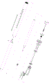
a three hundred and sixty degree trigger structure and a pen using the same as shown in fig. 1 to 2, the three hundred and sixty degree trigger structure includes a trigger 121, a displacement transmission member 2, an external mating terminal 31, a reset mechanism 6 and a pen.
The external mating terminal 31 is divided into an external trigger 311 and an external base 312.
The displacement transmission member 2 is specifically located between the trigger member 121 and the external mating terminal 31, and is sleeved on the external base 312.
An annular slide-in slope 41 is provided on the upper side of the displacement transmission member 2.
An annular cutting slope 42 is provided below the trigger 121.
At least one run-in ramp 41 or run-in ramp 42 is present between the triggering element 121 and the displacement transmission element 2. It is convenient that the triggering member 121 is forced to transmit to the displacement transmission member 2 to displace it, and the relationship between the actual deviation angle of the triggering member 121 and the actual distance between the displacement transmission members 2 is influenced by the specific angles of the slide-in slope 41 and the cut-in slope 42.
The reset mechanism 6 consists of two magnetic attractable objects;
the reset mechanism 6 is located between the external trigger 311 and the external base 312
The effect is as follows: by means of the magnetic attraction of the reset mechanism 6, after the external force disappears, the trigger member 121 is reset, i.e. the displacement transmission member 2 returns to the position before the force is applied. Waiting for the next arrival of external force.
The external trigger 311 and the external base 312 are coupled by a hinge. When one end of the external trigger 311 is pressed by the displacement transmission member 2, the other end of the external trigger 311 is displaced.
The three hundred and sixty degree trigger structure converts the lateral external force of three hundred and sixty degrees into vertical power through the trigger part 121 and the displacement transmission part 2, and then converts the lateral external force into final power required by any angle through the external matching terminal 31, and the final power can generate linkage effect with the pen, so that the pen is excited, closed, stopped, started or moved. The specific linkage effect is that the external matching terminal 31 is separated from the original constraint relation with the pen, the external matching terminal 31 forces the pen to change the current position of the pen or the external matching terminal 31 generates pressure on the pen.
In order to realize remote triggering, as an extension supplement, the pen is provided with a pry rod groove 9. A pry bar 91 is further arranged in the pry bar groove 9, and the pry bar 91 is fixedly hinged with the pen. The lever 91 is further provided with a remote triggering part 911 and a transmission triggering part 912. The external trigger 311 is divided into an external transmission part 3111 and an external force receiving part 3112 by using the hinge connection between the external trigger 311 and the external base 312 as a cutting point, and the external transmission part 3111 is the part in contact with the displacement transmission member 2. The transmission triggering part 912 is disposed on a side of the external force receiving part 3112, and the remote triggering part 911 is disposed on a side away from the external force receiving part 3112. When the remote trigger 911 is pressed to generate a lever principle, the transmission trigger 912 is pried up, and the external force receiving portion 3112 is pried up. The external trigger 311 and the pen are coupled to each other.
As practical application of the invention, the three-hundred-sixty-degree trigger structure is suitable for pens, and the pen structure for specific application comprises a movable rod T1, an outer rod T2, a pen core T3 and a return spring T4.
The movable rod T1 is sleeved in the outer rod T2.
The movable rod T1 is provided with a lock catch T11.
The outer rod T2 is provided with a through hole T21.
The pen core T3 is located in the movable rod T1 or the inner cavity formed by the combination of the movable rod T1 and the outer rod T2.
The three hundred and sixty degree trigger structure is integrally mounted to the rear of the outer pole T2 through an outer base 312.
The return spring T4 is disposed between the movable lever T1 and the outer base 312.
When the return spring T4 is disposed between the movable rod T1 and the outer base 312, the tail of the refill T3 needs to be fixed to the outer base 312 or the inner base 322, or a return spring T4 is additionally disposed between the refill T3 and the movable rod T1.
If the external mating terminal 31 is adopted, the external trigger 311 is further provided with a trigger hook 3113 passing through the through hole T21 to engage with the latch T11, and the trigger hook 3113 is not easily separated from the through hole T21.
When the lock catch T11 is positioned at the bottom of the through hole T21, the pen core is in a non-use state. At this time, the movable rod T1 is acted by the elastic force of the return spring T4, so that the degree of cooperation between the movable rod T1 and the outer rod T2 is maximized, and at this time, the space of the inner cavity formed by the movable rod T1 and the outer rod T2 is maximized, and the cartridge T3 is hidden in the inner cavity.
The length of the through hole T21 is at least larger than the distance difference between the state that the refill is stored in the inner cavity and the state that the refill is exposed.
When the movable rod T1 is manually controlled to move toward the end of the outer rod T2 to make the lock catch T11 engage with the trigger hook 3113, the length of the actual inner cavity is reduced due to the increased overlapping space between the movable rod T1 and the outer rod T2, so that the refill is exposed out of the inner cavity, and the engagement effect between the lock catch T11 and the trigger hook 3113 can avoid the influence of the return spring T4, so that the refill keeps continuously exposed, which is the use state.
The external force-receiving part 3112 is controlled by a three hundred sixty degree trigger structure or direct manual operation, so that the locking state between the lock catch T11 and the trigger hook 3113 is eliminated, and the reset spring T4 can make the lock catch T11 move to the bottom of the through hole T21, and then the lock catch T3526 is restored to the non-use state.
As an extension, the structure can be modified and optimized as follows, and the external base 312 adopts a separated structure. The installation is facilitated and the outer trigger 311 and outer base 312 are rotatable relative to the outer base 312 and the inner trigger 321 and inner base 322 are rotatable relative to the inner base 322. The lock catch T11 and the movable rod T1 are of a separate structure. Convenient for installation and replacement of consumables. The exterior of the three hundred and sixty degree trigger structure may also be covered with a protective sleeve 93. The front end of the movable rod T1 can be provided with an operating sleeve T12. In order to achieve the effect of automatic core retraction when the pen is placed on a platform or a bag, the outer diameters of the trigger ring 112 and the trigger 121 are larger than the outer diameter of the outer rod T2 and/or the outer diameter of the combination of the outer rod T2 and the outer trigger 311, so that the automatic triggering and floor triggering effects can be achieved, and when the pen is placed on a table, the trigger 121 is automatically triggered, so that the automatic core retraction is achieved.
Example 2:
a three hundred and sixty degree trigger structure and a pen using the same as shown in fig. 3 to 4, the three hundred and sixty degree trigger structure includes an external trigger set 1, a displacement transmission member 2, a trigger terminal set 3, a reset mechanism 6 and a pen.
The external trigger set 1 is a trigger ring assembly 11.
The trigger ring assembly 11 includes a retainer 111 and a trigger ring 112.
The trigger terminal group 3 is divided into external mating terminals 31.
The external mating terminal 31 is divided into an external trigger 311 and an external base 312.
The displacement transmission member 2 is specifically located between the external trigger group 1 and the trigger terminal group 3, and is sleeved on the limiting portion 111.
The stopper 111 and the outer base 312 are fixed to the outer base 312 or the inner base 322 by screws.
An annular slide-in slope 41 is provided on the lower side of the stopper 111 and/or the upper side of the displacement transmission member 2.
The upper and/or lower side of the trigger ring 112 and/or the lower side of the trigger element 121 are provided with annular cut-in ramps 42.
The trigger ring 112 is disposed between the position-limiting portion 111 and the outer base 312 or between the position-limiting portion 111 and the inner base 322.
At least one slide-in ramp 41 or cut-in ramp 42 is present between the external trigger group 1 and the displacement transmission element 2. It is convenient for the displacement transmission member 2 to be driven to displace after the external trigger set 1 is stressed, and the relationship between the actual deviation angle of the external trigger set 1 and the actual distance between the displacement transmission members 2 is influenced by the specific angles of the slide-in slope 41 and the cut-in slope 42.
The reset mechanism 6 is composed of two magnetic objects, and at least one of the magnetic objects is a permanent magnet;
the reset mechanism 6 may be located between the inner and outer trigger 311 and the outer base 312.
The effect is as follows: by means of the magnetic attraction of the reset mechanism 6, after the external force disappears, the external trigger set 1 is reset, that is, the displacement transmission member 2 returns to the position before the force is applied. Waiting for the next arrival of external force.
The external trigger 311 and the external base 312 are coupled by a hinge. When one end of the external trigger 311 is pressed by the displacement transmission member 2, the other end of the external trigger 311 is displaced.
The three-hundred-sixty degree triggering structure converts lateral external force of three-hundred-sixty degrees into vertical power through the external triggering group 1 and the displacement transmission piece 2, and then converts the lateral external force into final power required by any angle through the triggering terminal group 3, and the final power can generate a linkage effect with the pen, so that the pen is excited, closed, stopped, started or moved. The specific linkage effect is that the trigger terminal group 3 is separated from the original constraint relation with the pen, the trigger terminal group 3 forces the pen to change the current position of the pen or the trigger terminal group 3 generates pressure on the pen.
In order to realize remote triggering, as an extension supplement, the pen is provided with a pry rod groove 9. A pry bar 91 is further arranged in the pry bar groove 9, and the pry bar 91 is fixedly hinged with the pen. The lever 91 is further provided with a remote triggering part 911 and a transmission triggering part 912. The external trigger 311 is divided into an external transmission part 3111 and an external force receiving part 3112 by using the hinge connection between the external trigger 311 and the external base 312 as a cutting point, and the external transmission part 3111 is the part in contact with the displacement transmission member 2. The transmission triggering part 912 is disposed on a side of the external force receiving part 3112, and the remote triggering part 911 is disposed on a side away from the external force receiving part 3112. When the remote trigger 911 is pressed to generate a lever principle, the transmission trigger 912 is pried up, and the external force receiving portion 3112 is pried up. The external trigger 311 and the pen are coupled to each other.
As practical application of the invention, the three-hundred-sixty-degree trigger structure is suitable for pens, and the pen structure for specific application comprises a movable rod T1, an outer rod T2, a pen core T3 and a return spring T4.
The movable rod T1 is sleeved in the outer rod T2.
The movable rod T1 is provided with a lock catch T11.
The outer rod T2 is provided with a through hole T21.
The pen core T3 is located in the inner cavity formed by the combination of the movable rod T1 and the outer rod T2.
The three hundred and sixty degree trigger structure is integrally mounted to the tail of the outer pole T2 through the outer base 3122.
The return spring T4 is disposed between the movable lever T1 and the outer base 312.
When the return spring T4 is disposed between the movable rod T1 and the outer base 312, the tail of the pen core T3 needs to be fixed to the outer base 312.
With the external mating terminal 31, the external trigger 311 is further provided with a trigger hook 3113 passing through the through hole T21 to engage with the latch T11, and the trigger hook 3113 is not easily separated from the through hole T21.
When the lock catch T11 is positioned at the bottom of the through hole T21, the pen core is in a non-use state. At this time, the movable rod T1 is acted by the elastic force of the return spring T4, so that the degree of cooperation between the movable rod T1 and the outer rod T2 is maximized, and at this time, the space of the inner cavity formed by the movable rod T1 and the outer rod T2 is maximized, and the cartridge T3 is hidden in the inner cavity.
The length of the through hole T21 is at least larger than the distance difference between the state that the refill is stored in the inner cavity and the state that the refill is exposed.
When the movable rod T1 is manually controlled to move toward the end of the outer rod T2 to make the lock catch T11 engage with the trigger hook 3113, the length of the actual inner cavity is reduced due to the increased overlapping space between the movable rod T1 and the outer rod T2, so that the refill is exposed out of the inner cavity, and the engagement effect between the lock catch T11 and the trigger hook 3113 can avoid the influence of the return spring T4, so that the refill keeps continuously exposed, which is the use state.
The external force-receiving part 3112 is controlled by a three hundred sixty degree trigger structure or direct manual operation, so that the locking state between the lock catch T11 and the trigger hook 3113 is eliminated, and the reset spring T4 can make the lock catch T11 move to the bottom of the through hole T21, and then the lock catch T3526 is restored to the non-use state.
As an extension, the structure can be modified and optimized as follows, and the external base 312 adopts a separated structure. The installation is facilitated and the outer trigger 311 and outer base 312 are rotatable relative to the outer base 312 and the inner trigger 321 and inner base 322 are rotatable relative to the inner base 322. The lock catch T11 and the movable rod T1 are of a separate structure. Convenient for installation and replacement of consumables. The front end of the movable rod T1 can be provided with an operating sleeve T12. In order to achieve the effect of automatic core retraction when the pen is placed on a platform or a bag, the outer diameters of the trigger ring 112 and the trigger 121 are larger than the outer diameter of the outer rod T2 and/or the outer diameter of the combination of the outer rod T2 and the external trigger 311, so that the automatic triggering and floor triggering effects can be achieved, and when the pen is placed on a desktop, the external trigger set 1 is automatically triggered, thereby causing automatic core retraction.
Example 3:
as shown in fig. 5 to 6, the three-hundred-sixty degree trigger structure comprises an external trigger group 1, a displacement transmission member 2, a trigger terminal group 3, a reset mechanism 6 and a pen.
The external trigger set 1 is a trigger ring assembly 11.
The trigger ring assembly 11 includes a retainer 111 and a trigger ring 112.
The trigger terminal group 3 is divided into an external mating terminal 31 and an internal mating terminal 32.
The external mating terminal 31 is divided into an external trigger 311 and an external base 312.
The internal mating terminal 32 is divided into an internal trigger 321 and an internal base 322.
The displacement transmission member 2 is specifically located between the external trigger group 1 and the trigger terminal group 3, and is sleeved on the limiting portion 111, the external base 312 or the internal base 322.
The position-limiting portion 111 and the external base 312 are fixed to the external base 312 by screws.
An annular slide-in slope 41 is provided on the lower side of the stopper 111 and/or the upper side of the displacement transmission member 2.
The upper and/or lower side of the trigger ring 112 and/or the lower side of the trigger element 121 are provided with annular cut-in ramps 42.
The trigger ring 112 is disposed between the position-limiting portion 111 and the outer base 312 or between the position-limiting portion 111 and the inner base 322.
At least one slide-in ramp 41 or cut-in ramp 42 is present between the external trigger group 1 and the displacement transmission element 2. It is convenient for the displacement transmission member 2 to be driven to displace after the external trigger set 1 is stressed, and the relationship between the actual deviation angle of the external trigger set 1 and the actual distance between the displacement transmission members 2 is influenced by the specific angles of the slide-in slope 41 and the cut-in slope 42.
The reset mechanism 6 is composed of two permanent magnets.
The reset mechanism 6 is respectively located on the external trigger 311 and the pen, and the two permanent magnets are opposite in the same level to generate repulsion.
The effect is as follows: by using the repulsive force of the reset mechanism 6, after the external force disappears, the external trigger set 1 is reset, that is, the displacement transmission member 2 returns to the position before being stressed. Waiting for the next arrival of external force.
The external trigger 311 and the external base 312 are coupled by a hinge. When one end of the external trigger 311 is pressed by the displacement transmission member 2, the other end of the external trigger 311 is displaced.
The three-hundred-sixty degree triggering structure converts lateral external force of three-hundred-sixty degrees into vertical power through the external triggering group 1 and the displacement transmission piece 2, and then converts the lateral external force into final power required by any angle through the triggering terminal group 3, and the final power can generate a linkage effect with the pen, so that the pen is excited, closed, stopped, started or moved. The specific linkage effect is that the trigger terminal group 3 is separated from the original constraint relation with the pen, the trigger terminal group 3 forces the pen to change the current position of the pen or the trigger terminal group 3 generates pressure on the pen.
In order to satisfy the structure of the external trigger 311 in each case, as an extension, the external trigger 311 is a cutting point formed by the hinge connection between the external trigger 311 and the external base 312, and the external trigger 311 is divided into an external transmission part 3111 and an external force receiving part 3112, and the part in contact with the displacement transmission part 2 is the external transmission part 3111. When the angle D1 between the external transmission part 3111 and the axis C1 is greater than 90 °, the external transmission part 3111 can be directly driven by the displacement transmission member 2. However, when the angle D1 between the external transmission part 3111 and the axis C1 is less than or equal to 90 °, the displacement transmission member 2 is difficult to transmit the external transmission part 3111 unless the hinged point between the external trigger 311 and the external base 312 is far from the displacement transmission member 2, so as to overcome the above-mentioned problem. The lower side of the displacement transmission member 2 is further provided with a transmission extension column 21 for overcoming the contact drop caused by the excessively small included angle between the displacement transmission member 2 and the external transmission part 3111.
In order to realize remote triggering, as an extension supplement, the pen is provided with a pry rod groove 9. A pry bar 91 is further arranged in the pry bar groove 9, and the pry bar 91 is fixedly hinged with the pen. The lever 91 is further provided with a remote triggering part 911 and a transmission triggering part 912. The external trigger 311 is divided into an external transmission part 3111 and an external force receiving part 3112 by using the hinge connection between the external trigger 311 and the external base 312 as a cutting point, and the external transmission part 3111 is the part in contact with the displacement transmission member 2. The transmission triggering part 912 is disposed on a side of the external force receiving part 3112, and the remote triggering part 911 is disposed on a side away from the external force receiving part 3112. When the remote trigger 911 is pressed to generate a lever principle, the transmission trigger 912 is pried up, and the external force receiving portion 3112 is pried up. The external trigger 311 and the pen are coupled to each other.
As practical application of the invention, the three-hundred-sixty-degree trigger structure is suitable for pens, and the pen structure for specific application comprises a movable rod T1, an outer rod T2, a pen core T3 and a return spring T4.
The movable rod T1 is sleeved in the outer rod T2.
The movable rod T1 is provided with a lock catch T11.
The outer rod T2 is provided with a through hole T21.
The pen core T3 is located in the inner cavity formed by the combination of the movable rod T1 and the outer rod T2.
The three hundred and sixty degree trigger structure is integrally mounted to the rear of the outer pole T2 through an outer base 312.
The return spring T4 is disposed between the movable lever T1 and the outer base 312.
When the return spring T4 is disposed between the movable rod T1 and the outer seat 312, the tail of the cartridge T3 needs to be fixed to the outer seat 312.
With the external mating terminal 31, the external trigger 311 is further provided with a trigger hook 3113 passing through the through hole T21 to engage with the latch T11, and the trigger hook 3113 is not easily separated from the through hole T21.
When the lock catch T11 is positioned at the bottom of the through hole T21, the pen core is in a non-use state. At this time, the movable rod T1 is acted by the elastic force of the return spring T4, so that the degree of cooperation between the movable rod T1 and the outer rod T2 is maximized, and at this time, the space of the inner cavity formed by the movable rod T1 and the outer rod T2 is maximized, and the cartridge T3 is hidden in the inner cavity.
The length of the through hole T21 is at least larger than the distance difference between the state that the refill is stored in the inner cavity and the state that the refill is exposed.
When the movable rod T1 is manually controlled to move toward the end of the outer rod T2 to make the lock catch T11 engage with the trigger hook 3113, the length of the actual inner cavity is reduced due to the increased overlapping space between the movable rod T1 and the outer rod T2, so that the refill is exposed out of the inner cavity, and the engagement effect between the lock catch T11 and the trigger hook 3113 can avoid the influence of the return spring T4, so that the refill keeps continuously exposed, which is the use state.
The external force-receiving part 3112 is controlled by a three hundred sixty degree trigger structure or direct manual operation, so that the locking state between the lock catch T11 and the trigger hook 3113 is eliminated, and the reset spring T4 can make the lock catch T11 move to the bottom of the through hole T21, and then the lock catch T3526 is restored to the non-use state.
As an extension, the structure can be modified and optimized as follows, and the external base 312 adopts a separated structure. The installation is facilitated and the outer trigger 311 and outer base 312 are rotatable relative to the outer base 312 and the inner trigger 321 and inner base 322 are rotatable relative to the inner base 322. The lock catch T11 and the movable rod T1 are of a separate structure. Convenient for installation and replacement of consumables. The front end of the movable rod T1 can be provided with an operating sleeve T12. In order to achieve the effect of automatic core retraction when the pen is placed on a platform or a bag, the outer diameters of the trigger ring 112 and the trigger 121 are larger than the outer diameter of the outer rod T2 and/or the outer diameter of the combination of the outer rod T2 and the external trigger 311, so that the automatic triggering and floor triggering effects can be achieved, and when the pen is placed on a desktop, the external trigger set 1 is automatically triggered, thereby causing automatic core retraction.
Example 4:
a three hundred and sixty degree trigger configuration and a pen employing the same, as shown in fig. 7 to 11, includes an external trigger set 1, a displacement transmission member 2, a trigger terminal set 3, a reset mechanism 6 and a pen.
The external trigger set 1 is a trigger ring assembly 11.
The trigger ring assembly 11 includes a retainer 111 and a trigger ring 112.
The set of trigger terminals 3 is divided into external mating terminals 31 and/or internal mating terminals 32.
The external mating terminal 31 is divided into an external trigger 311 and an external base 312.
The internal mating terminal 32 is divided into an internal trigger 321 and an internal base 322.
The displacement transmission member 2 is specifically located between the external trigger group 1 and the trigger terminal group 3, and is sleeved on the limiting portion 111.
An internal linkage rod 22 is also provided below the displacement drive member 2 when an internal engagement terminal 32 is employed. The inner base 322 is further provided with a linkage through hole 3221. The internal linkage rod 22 passes through the linkage through hole 3221 and contacts the internal trigger 321.
When both the outer mating terminal 31 and the inner mating terminal 32 are used, one of the outer base 312 and the inner base 322 may be used.
The space between the position-limiting part 111 and the outer base 312 or the space between the position-limiting part 111 and the inner base 322 is fixed on the outer base 312 or the inner base 322 by screw threads.
An annular slide-in slope 41 is provided on the lower side of the stopper 111 and/or the upper side of the displacement transmission member 2.
The upper and/or lower side of the trigger ring 112 and/or the lower side of the trigger element 121 are provided with annular cut-in ramps 42.
The trigger ring 112 is disposed between the position-limiting portion 111 and the outer base 312 or between the position-limiting portion 111 and the inner base 322.
At least one slide-in ramp 41 or cut-in ramp 42 is present between the external trigger group 1 and the displacement transmission element 2. It is convenient for the displacement transmission member 2 to be driven to displace after the external trigger set 1 is stressed, and the relationship between the actual deviation angle of the external trigger set 1 and the actual distance between the displacement transmission members 2 is influenced by the specific angles of the slide-in slope 41 and the cut-in slope 42.
The reset mechanism 6 is composed of two permanent magnets.
The reset mechanism 6 is respectively located on the external trigger 311 and the pen, and the two permanent magnets are opposite in the same level to generate repulsion.
The effect is as follows: by using the repulsive force of the reset mechanism 6, after the external force disappears, the external trigger set 1 is reset, that is, the displacement transmission member 2 returns to the position before being stressed. Waiting for the next arrival of external force.
The external trigger 311 and the external base 312 are coupled by a hinge. When one end of the external trigger 311 is pressed by the displacement transmission member 2, the other end of the external trigger 311 is displaced.
The three-hundred-sixty degree triggering structure converts lateral external force of three-hundred-sixty degrees into vertical power through the external triggering group 1 and the displacement transmission piece 2, and then converts the lateral external force into final power required by any angle through the triggering terminal group 3, and the final power can generate a linkage effect with the pen, so that the pen is excited, closed, stopped, started or moved. The specific linkage effect is that the trigger terminal group 3 is separated from the original constraint relation with the pen, the trigger terminal group 3 forces the pen to change the current position of the pen or the trigger terminal group 3 generates pressure on the pen.
To achieve the top-triggering effect, a central pressing member 71 and a pressing limiting member 72 are further disposed in the triggering ring assembly 11. The middle pressing member 71 is movably slid in the position-limiting portion 111, the outer base 312 and/or the inner base 322. The pressing limiting member 72 is fixed to the middle pressing member 71 by a screw, a snap, an adhesive, or a magnetic force after the middle pressing member 71 passes through the limiting portion 111, the external base 312, and/or the internal base 322, so as to prevent the middle pressing member 71 from slipping off the limiting portion 111, the external base 312, and/or the internal base 322. The middle pressing member 71 has a pressing portion 711 at one end thereof and an upper side abutting against the inner trigger 321 at the other end thereof.
When the pressing part 711 is pressed by an external force, the central control pressing part 71 is transmitted to the inner trigger 321, so that a linkage effect is generated between the inner trigger 321 and the pen. Causing the pen to be fired, turned off, terminated, activated or moved.
In order to realize the effect of top self-locking, the lower side of the pressing part 711 is further provided with a self-locking buckle 712. The position-limiting portion 111 is further provided with a self-locking slot 1111 matching with the self-locking buckle 712. The self-locking button 712 and the self-locking slot 1111 are engaged by a screw, a snap and/or a magnetic attraction. The self-locking latch 712 and the self-locking slot 1111 can keep the inner trigger 321 in a downward moving state, i.e., a state in which the inner trigger 321 is continuously in contact with the pen. The internal trigger 321 continues to be interlocked with the pen.
In order to satisfy the structure of the external trigger 311 in each case, as an extension, the external trigger 311 is a cutting point formed by the hinge connection between the external trigger 311 and the external base 312, and the external trigger 311 is divided into an external transmission part 3111 and an external force receiving part 3112, and the part in contact with the displacement transmission part 2 is the external transmission part 3111. When the angle D1 between the external transmission part 3111 and the axis C1 is greater than 90 °, the external transmission part 3111 can be directly driven by the displacement transmission member 2. However, when the angle D1 between the external transmission part 3111 and the axis C1 is less than or equal to 90 °, the displacement transmission member 2 is difficult to transmit the external transmission part 3111 unless the hinged point between the external trigger 311 and the external base 312 is far from the displacement transmission member 2, so as to overcome the above-mentioned problem. The lower side of the displacement transmission member 2 is further provided with a transmission extension column 21 for overcoming the contact drop caused by the excessively small included angle between the displacement transmission member 2 and the external transmission part 3111.
In order to realize remote triggering, as an extension supplement, the pen is provided with a pry rod groove 9. A pry bar 91 is further arranged in the pry bar groove 9, and the pry bar 91 is fixedly hinged with the pen. The lever 91 is further provided with a remote triggering part 911 and a transmission triggering part 912. The external trigger 311 is divided into an external transmission part 3111 and an external force receiving part 3112 by using the hinge connection between the external trigger 311 and the external base 312 as a cutting point, and the external transmission part 3111 is the part in contact with the displacement transmission member 2. The transmission triggering part 912 is disposed on a side of the external force receiving part 3112, and the remote triggering part 911 is disposed on a side away from the external force receiving part 3112. When the remote trigger 911 is pressed to generate a lever principle, the transmission trigger 912 is pried up, and the external force receiving portion 3112 is pried up. The external trigger 311 and the pen are coupled to each other.
As practical application of the invention, the three-hundred-sixty-degree trigger structure is suitable for pens, and the pen structure for specific application comprises a movable rod T1, an outer rod T2, a pen core T3 and a return spring T4.
The movable rod T1 is sleeved in the outer rod T2.
The movable rod T1 is provided with a lock catch T11.
The outer rod T2 is provided with a through hole T21.
The pen core T3 is located in the inner cavity formed by the combination of the movable rod T1 and the outer rod T2.
The three hundred and sixty degree trigger structure is integrally mounted to the tail of the outer pole T2 through the outer base 312 or the inner base 322.
The return spring T4 is disposed between the movable rod T1 and the pen core T3.
Meanwhile, the external mating terminal 31 and the internal mating terminal 32 are adopted, and the external trigger 311 is further provided with a trigger hook 3113 passing through the through hole T21 and engaging with the latch T11. The inner trigger 321 is further provided with a disengaging ramp 3212. When the inner trigger 321 moves downward, the engaging relation between the latch T11 and the trigger hook 3113 can be forced to disengage by the engaging slope 3212. The trigger hook 3113 is not easily separated from the through hole T21.
When the lock catch T11 is positioned at the bottom of the through hole T21, the pen core is in a non-use state. At this time, the movable rod T1 is acted by the elastic force of the return spring T4, so that the degree of cooperation between the movable rod T1 and the outer rod T2 is maximized, and at this time, the space of the inner cavity formed by the movable rod T1 and the outer rod T2 is maximized, and the cartridge T3 is hidden in the inner cavity.
The length of the through hole T21 is at least larger than the distance difference between the state that the refill is stored in the inner cavity and the state that the refill is exposed.
When the movable rod T1 is manually controlled to move toward the end of the outer rod T2 to make the lock catch T11 engage with the trigger hook 3113, the length of the actual inner cavity is reduced due to the increased overlapping space between the movable rod T1 and the outer rod T2, so that the refill is exposed out of the inner cavity, and the engagement effect between the lock catch T11 and the inner ring hook T22 or the trigger hook 3113 can avoid the influence of the return spring T4, so that the refill keeps the state of being exposed out, which is the use state.
The external force-receiving part 3112 is controlled by a three hundred sixty degree trigger structure or direct manual operation, so that the locking state between the lock catch T11 and the trigger hook 3113 is eliminated, and the reset spring T4 can make the lock catch T11 move to the bottom of the through hole T21, and then the lock catch T3526 is restored to the non-use state.
As an extension, the structure can be modified and optimized as follows, and the external base 312 or the internal base 322 adopts a separated structure. The installation is facilitated and the outer trigger 311 and outer base 312 are rotatable relative to the outer base 312 and the inner trigger 321 and inner base 322 are rotatable relative to the inner base 322. The lock catch T11 and the movable rod T1 are of a separate structure. Convenient for installation and replacement of consumables.
In order to achieve the effect of automatic core retraction when the pen is placed on a platform or a bag, the outer diameters of the trigger ring 112 and the trigger 121 are larger than the outer diameter of the outer rod T2 and/or the outer diameter of the combination of the outer rod T2 and the external trigger 311, so that the automatic triggering and floor triggering effects can be achieved, and when the pen is placed on a desktop, the external trigger set 1 is automatically triggered, thereby causing automatic core retraction.
Example 5:
a three hundred sixty degree trigger configuration and pen employing the same as shown in fig. 12 to 14 includes a trigger 121, an internal engagement terminal 32, a reset mechanism 6 and a pen.
The internal mating terminal 32 is divided into an internal trigger 321 and an internal base 322.
The trigger 121 and the inner base 322 are connected by means of a joint bearing.
The reset mechanism 6 is composed of one or more substances with elasticity, elasticity or magnetic force.
The reset mechanism 6 can be located between the inner trigger 321 and the inner base 322, and between the inner trigger 321 and the pen.
An adjusting inner ring groove 3211 is formed at an upper side of the inner trigger 321. The lower end of the trigger 121 is further provided with an adjusting rod 1211. One end of the adjusting rod 1211 is positioned in the adjusting inner groove 3211.
The adjusting rod 1211 rotates around the joint bearing between the trigger 121 and the inner base 322 to form an arc angle a1 with the axis C1, which is greater than a groove surface angle B1 between the inner groove section of the inner ring groove 3211 and the axis C1.
The actual deflection angle of the trigger 121 and the actual travel distance of the interior engagement terminal 32 are determined by the difference between the included slot surface angle B1 and the included arc angle a 1.
The effect is as follows: by using the elastic force, elasticity, magnetic force and/or repulsive force of the reset mechanism 6, after the external force disappears, the trigger 121 is set right again to wait for the next arrival of the external force.
When the trigger 121 is subjected to an external force in any one of three hundred and sixty degrees, the inner trigger 321 is forced to move downward by adjusting the inner ring groove 3211. The integral downward movement of the inner trigger 321 will cause a linkage effect between the inner trigger 321 and the pen. Causing the pen to be fired, turned off, terminated, activated or moved. The specific linkage effect is that the trigger terminal group 3 is separated from the original constraint relation with the pen, the trigger terminal group 3 forces the pen to change the current position of the pen or the trigger terminal group 3 generates pressure on the pen.
As practical application of the invention, the three-hundred-sixty-degree trigger structure is suitable for pens, and the pen structure for specific application comprises a movable rod T1, an outer rod T2, a pen core T3 and a return spring T4.
The movable rod T1 is sleeved in the outer rod T2.
The movable rod T1 is provided with a lock catch T11.
The outer rod T2 is provided with an inner ring hook T22.
The pen core T3 is located in the inner cavity formed by the combination of the movable rod T1 and the outer rod T2.
The three hundred and sixty degree trigger structure is integrally mounted to the tail of the outer pole T2 through the inner base 322.
The return spring T4 is disposed between the movable rod T1 and the pen core T3.
When the lock catch T11 is positioned at the bottom of the anti-slip ring convex T23, the pen core is in a non-use state. At this time, the movable rod T1 is acted by the elastic force of the return spring T4, so that the degree of cooperation between the movable rod T1 and the outer rod T2 is maximized, and at this time, the space of the inner cavity formed by the movable rod T1 and the outer rod T2 is maximized, and the cartridge T3 is hidden in the inner cavity.
The length of the through hole T21 is at least larger than the distance difference between the state that the refill is stored in the inner cavity and the state that the refill is exposed.
When the movable rod T1 is manually controlled to move toward the end of the outer rod T2 to engage the lock catch T11 with the inner ring hook T22, the length of the actual inner cavity is reduced due to the increased overlapping space between the movable rod T1 and the outer rod T2, so that the refill is exposed, and the engagement effect between the lock catch T11 and the inner ring hook T22 can avoid the influence of the return spring T4, so that the refill keeps the state of being exposed, which is the use state.
And the three-hundred sixty degree triggering structure enables the clamping state of the lock catch T11 and the inner ring hook T22 to disappear, so that the reset spring T4 enables the lock catch T11 to move to the bottom of the anti-slip ring convex T23, and the lock catch T11 is recovered to the non-use state.
As an extension supplement, the structure can be adjusted and optimized as follows, the movable rod T1 is also provided with an extending column T13, and the lock catch T11 is mainly arranged or positioned on the extending column T13.
In order to achieve the effect of automatic core retraction when the pen is placed on a platform or a bag, the outer diameters of the trigger ring 112 and the trigger 121 are larger than the outer diameter of the outer rod T2 and/or the outer diameter of the combination of the outer rod T2 and the external trigger 311, so that the automatic triggering and floor triggering effects can be achieved, and when the pen is placed on a desktop, the external trigger set 1 is automatically triggered, thereby causing automatic core retraction.
Example 6:
a three hundred and sixty degree trigger configuration and a pen employing the same, as shown in fig. 15 to 18, includes an external trigger set 1, a displacement transmission member 2, a trigger terminal set 3, a reset mechanism 6 and a pen.
The external trigger set 1 is a trigger ring assembly 11.
The trigger ring assembly 11 includes a retainer 111 and a trigger ring 112.
The trigger terminal group 3 is divided into external mating terminals 31.
The external mating terminal 31 is divided into an external trigger 311 and an external base 312.
The displacement transmission member 2 is located between the external trigger group 1 and the trigger terminal group 3
The position-limiting portion 111 and the external base 312 are fixed to the external base 312 or the internal base 322 by screwing.
An annular slide-in slope 41 is provided on the lower side of the stopper 111 and/or the upper side of the displacement transmission member 2.
The upper and/or lower side of the trigger ring 112 and/or the lower side of the trigger element 121 are provided with annular cut-in ramps 42.
The trigger ring 112 is disposed between the position-limiting portion 111 and the outer base 312 or between the position-limiting portion 111 and the inner base 322.
At least one slide-in ramp 41 or cut-in ramp 42 is present between the external trigger group 1 and the displacement transmission element 2. It is convenient for the displacement transmission member 2 to be driven to displace after the external trigger set 1 is stressed, and the relationship between the actual deviation angle of the external trigger set 1 and the actual distance between the displacement transmission members 2 is influenced by the specific angles of the slide-in slope 41 and the cut-in slope 42.
The return mechanism 6 is composed of a spring.
The reset mechanism 6 may be located between the outer trigger 311 and the outer base 312.
The effect is as follows: by means of the elastic force of the reset mechanism 6, after the external force disappears, the external trigger set 1 is reset, that is, the displacement transmission member 2 returns to the position before being stressed. Waiting for the next arrival of external force.
The external trigger 311 and the external base 312 are coupled by a hinge. When one end of the external trigger 311 is pressed by the displacement transmission member 2, the other end of the external trigger 311 is displaced.
The three-hundred-sixty degree triggering structure converts lateral external force of three-hundred-sixty degrees into vertical power through the external triggering group 1 and the displacement transmission piece 2, and then converts the lateral external force into final power required by any angle through the triggering terminal group 3, and the final power can generate a linkage effect with the pen, so that the pen is excited, closed, stopped, started or moved. The specific linkage effect is that the trigger terminal group 3 is separated from the original constraint relation with the pen, the trigger terminal group 3 forces the pen to change the current position of the pen or the trigger terminal group 3 generates pressure on the pen.
In order to make the function of the limiting part richer and have the effects of rotary triggering and strong self-locking, as an extension supplement, the three-hundred-sixty-degree triggering structure is formed by additionally arranging a middle shaft rotating column 81, an internal regulator 82 and a fixing piece 83. The internal actuator 82 is threadably engaged with the pen, the outer base 312 or the inner base 322. The central axis rotation post 81 is specifically positioned between the outer base 312 and the inner actuator 82 or between the inner actuator 82 and the inner base 322. The displacement transmission member 2 is instead sleeved on the middle shaft rotating column 81, the external base 312 or the internal base 322. The upper end of the middle shaft rotating column 81 is provided with an operation clamping protrusion 811. The lower end of the middle shaft rotating column 81 is provided with a rotating clamping convex 812. The operation protrusion 811 and the rotation protrusion 812 are both non-cylindrical. The stopper 111 is fitted over the operation projection 811 and fixed by the fixing member 83. The fixing member 83 is fixed to the bottom bracket rotary post 81 by means of a screw, a snap, an adhesive, or a magnetic force. The rotating boss 812 is received in the inner actuator 82.
Since the operation protrusion 811 and the rotation protrusion 812 are both non-cylindrical, when the limiting portion 111 rotates in forward or reverse direction, the central shaft rotation post 81 rotates, and the rotation of the central shaft rotation post 81 drives the inner adjuster 82 to rotate accordingly. Thus, the position of the internal regulator 82 is indirectly controlled, but the position of the stopper 111 and the position of the central rotary post 81 themselves are kept constant, and the position of the internal regulator 82 can be controlled by rotating the stopper 111 without affecting the original function. While the internal actuator 82 may provide a stable and continuous linkage with the pen.
In order to realize remote triggering, as an extension supplement, the pen is provided with a pry rod groove 9. A pry bar 91 is further arranged in the pry bar groove 9, and the pry bar 91 is fixedly hinged with the pen. The lever 91 is further provided with a remote triggering part 911 and a transmission triggering part 912. The external trigger 311 is divided into an external transmission part 3111 and an external force receiving part 3112 by using the hinge connection between the external trigger 311 and the external base 312 as a cutting point, and the external transmission part 3111 is the part in contact with the displacement transmission member 2. The transmission triggering part 912 is disposed on a side of the external force receiving part 3112, and the remote triggering part 911 is disposed on a side away from the external force receiving part 3112. When the remote trigger 911 is pressed to generate a lever principle, the transmission trigger 912 is pried up, and the external force receiving portion 3112 is pried up. The external trigger 311 and the pen are coupled to each other.
As practical application of the invention, the three-hundred-sixty-degree trigger structure is suitable for pens, and the pen structure for specific application comprises a movable rod T1, an outer rod T2, a pen core T3 and a return spring T4.
The movable rod T1 is sleeved in the outer rod T2.
The movable rod T1 is provided with a lock catch T11.
The outer rod T2 is provided with a through hole T21.
The pen core T3 is located in the inner cavity formed by the combination of the movable rod T1 and the outer rod T2.
The three hundred and sixty degree trigger structure is integrally mounted to the rear of the outer pole T2 through an outer base 312.
The return spring T4 is disposed between the movable rod T1 and the pen core T3.
With the external mating terminal 31, the external trigger 311 is further provided with a trigger hook 3113 passing through the through hole T21 to engage with the latch T11, and the trigger hook 3113 is not easily separated from the through hole T21.
When the lock catch T11 is positioned at the bottom of the through hole T21, the pen core is in a non-use state. At this time, the movable rod T1 is acted by the elastic force of the return spring T4, so that the degree of cooperation between the movable rod T1 and the outer rod T2 is maximized, and at this time, the space of the inner cavity formed by the movable rod T1 and the outer rod T2 is maximized, and the cartridge T3 is hidden in the inner cavity.
The length of the through hole T21 is at least larger than the distance difference between the state that the refill is stored in the inner cavity and the state that the refill is exposed.
When the movable rod T1 is manually controlled to move toward the end of the outer rod T2 to make the lock catch T11 engage with the trigger hook 3113, the length of the actual inner cavity is reduced due to the increased overlapping space between the movable rod T1 and the outer rod T2, so that the refill is exposed out of the inner cavity, and the engagement effect between the lock catch T11 and the trigger hook 3113 can avoid the influence of the return spring T4, so that the refill keeps continuously exposed, which is the use state.
The external force-receiving part 3112 is controlled by a three-hundred sixty degree trigger structure or direct manual operation, so that the engagement state between the lock catch T11 and the trigger hook 3113 is lost, and the reset spring T4 can make the lock catch T11 move to the bottom of the through hole T21, and then the lock catch T3526 is restored to the non-use state.
As an extension, the structure can be modified and optimized as follows, and the external base 312 adopts a separated structure. The installation is facilitated and the outer trigger 311 and outer base 312 are rotatable relative to the outer base 312 and the inner trigger 321 and inner base 322 are rotatable relative to the inner base 322. The lock catch T11 and the movable rod T1 are of a separate structure. Convenient for installation and replacement of consumables. The movable rod T1 is further provided with an extension column T13, and the lock catch T11 is mainly mounted or positioned on the extension column T13. The movable rod T1 adopts a separated structure and is divided into a movable inner rod TA1 and a movable loop rod TA2, and the movable inner rod TA1 and the movable loop rod TA2 are directly combined in a thread, buckle or magnetic attraction mode.
In order to achieve the effect of automatic core retraction when the pen is placed on a platform or a bag, the outer diameters of the trigger ring 112 and the trigger 121 are larger than the outer diameter of the outer rod T2 and/or the outer diameter of the combination of the outer rod T2 and the external trigger 311, so that the automatic triggering and floor triggering effects can be achieved, and when the pen is placed on a desktop, the external trigger set 1 is automatically triggered, thereby causing automatic core retraction.
In order to make the strong self-locking of the position-limiting part, before the strong self-locking, the buckling state of the pen is released, and the pen returns to the core-collecting state, and the pen core is stored in the inner cavity, the bottom of the inner regulator 82 is also provided with a regulating separation slope 821. The adjustment release slope 821 can release the engagement between the lock catch T11 and the inner ring hook T22 or the trigger hook 3113, and if the inner adjuster 82 is not manually rotated to unlock, the lock catch T11 will be continuously affected by the adjustment release slope 821 and cannot form the engagement effect with the inner ring hook T22 or the trigger hook 3113.
In the description of the present invention, it should be noted that the terms "mounted," "connected," and "connected" are to be construed broadly and may be, for example, fixedly connected, detachably connected, or integrally connected unless otherwise explicitly stated or limited. They may be mechanically coupled, directly coupled, indirectly coupled through intervening media, or may be interconnected between two elements. The specific meaning of the above terms in the present invention can be understood by those of ordinary skill in the art through specific situations.
The foregoing is a preferred embodiment of the present invention, and it will be apparent to those skilled in the art that various changes and modifications may be made without departing from the spirit of the invention, and these should be considered as the scope of the invention.
It will be evident to those skilled in the art that the invention is not limited to the details of the foregoing illustrative embodiments, and that the present invention may be embodied in other specific forms without departing from the spirit or essential attributes thereof. The present embodiments are therefore to be considered in all respects as illustrative and not restrictive, the scope of the invention being indicated by the appended claims rather than by the foregoing description, and all changes which come within the meaning and range of equivalency of the claims are therefore intended to be embraced therein. Any reference sign in a claim should not be construed as limiting the claim concerned.
Furthermore, it should be understood that although the present description refers to embodiments, not every embodiment may contain only a single embodiment, and such description is for clarity only, and those skilled in the art should integrate the description, and the embodiments may be combined as appropriate to form other embodiments understood by those skilled in the art.