CN112672917A - Seat arrangement switching unit - Google Patents
Seat arrangement switching unit Download PDFInfo
- Publication number
- CN112672917A CN112672917A CN201980059170.8A CN201980059170A CN112672917A CN 112672917 A CN112672917 A CN 112672917A CN 201980059170 A CN201980059170 A CN 201980059170A CN 112672917 A CN112672917 A CN 112672917A
- Authority
- CN
- China
- Prior art keywords
- seat
- arrangement
- mounting frame
- seats
- support base
- Prior art date
- Legal status (The legal status is an assumption and is not a legal conclusion. Google has not performed a legal analysis and makes no representation as to the accuracy of the status listed.)
- Pending
Links
- 238000005096 rolling process Methods 0.000 claims description 14
- 238000010586 diagram Methods 0.000 description 7
- 230000008859 change Effects 0.000 description 5
- 238000000034 method Methods 0.000 description 4
- 239000011347 resin Substances 0.000 description 4
- 229920005989 resin Polymers 0.000 description 4
- 230000009471 action Effects 0.000 description 3
- 108010066114 cabin-2 Proteins 0.000 description 3
- 239000002184 metal Substances 0.000 description 2
- 230000001133 acceleration Effects 0.000 description 1
- 230000008878 coupling Effects 0.000 description 1
- 238000010168 coupling process Methods 0.000 description 1
- 238000005859 coupling reaction Methods 0.000 description 1
- 230000000694 effects Effects 0.000 description 1
- 230000005484 gravity Effects 0.000 description 1
- 230000002452 interceptive effect Effects 0.000 description 1
- 230000000149 penetrating effect Effects 0.000 description 1
- 238000000926 separation method Methods 0.000 description 1
Images


Classifications
-
- B—PERFORMING OPERATIONS; TRANSPORTING
- B60—VEHICLES IN GENERAL
- B60N—SEATS SPECIALLY ADAPTED FOR VEHICLES; VEHICLE PASSENGER ACCOMMODATION NOT OTHERWISE PROVIDED FOR
- B60N2/00—Seats specially adapted for vehicles; Arrangement or mounting of seats in vehicles
- B60N2/005—Arrangement or mounting of seats in vehicles, e.g. dismountable auxiliary seats
- B60N2/01—Arrangement of seats relative to one another
-
- B—PERFORMING OPERATIONS; TRANSPORTING
- B60—VEHICLES IN GENERAL
- B60N—SEATS SPECIALLY ADAPTED FOR VEHICLES; VEHICLE PASSENGER ACCOMMODATION NOT OTHERWISE PROVIDED FOR
- B60N2/00—Seats specially adapted for vehicles; Arrangement or mounting of seats in vehicles
- B60N2/005—Arrangement or mounting of seats in vehicles, e.g. dismountable auxiliary seats
- B60N2/015—Attaching seats directly to vehicle chassis
-
- B—PERFORMING OPERATIONS; TRANSPORTING
- B60—VEHICLES IN GENERAL
- B60N—SEATS SPECIALLY ADAPTED FOR VEHICLES; VEHICLE PASSENGER ACCOMMODATION NOT OTHERWISE PROVIDED FOR
- B60N2/00—Seats specially adapted for vehicles; Arrangement or mounting of seats in vehicles
- B60N2/02—Seats specially adapted for vehicles; Arrangement or mounting of seats in vehicles the seat or part thereof being movable, e.g. adjustable
- B60N2/04—Seats specially adapted for vehicles; Arrangement or mounting of seats in vehicles the seat or part thereof being movable, e.g. adjustable the whole seat being movable
- B60N2/06—Seats specially adapted for vehicles; Arrangement or mounting of seats in vehicles the seat or part thereof being movable, e.g. adjustable the whole seat being movable slidable
- B60N2/07—Slide construction
- B60N2/0702—Slide construction characterised by its cross-section
- B60N2/072—Complex cross-section, e.g. obtained by extrusion
-
- B—PERFORMING OPERATIONS; TRANSPORTING
- B60—VEHICLES IN GENERAL
- B60N—SEATS SPECIALLY ADAPTED FOR VEHICLES; VEHICLE PASSENGER ACCOMMODATION NOT OTHERWISE PROVIDED FOR
- B60N2/00—Seats specially adapted for vehicles; Arrangement or mounting of seats in vehicles
- B60N2/02—Seats specially adapted for vehicles; Arrangement or mounting of seats in vehicles the seat or part thereof being movable, e.g. adjustable
- B60N2/04—Seats specially adapted for vehicles; Arrangement or mounting of seats in vehicles the seat or part thereof being movable, e.g. adjustable the whole seat being movable
- B60N2/06—Seats specially adapted for vehicles; Arrangement or mounting of seats in vehicles the seat or part thereof being movable, e.g. adjustable the whole seat being movable slidable
- B60N2/08—Seats specially adapted for vehicles; Arrangement or mounting of seats in vehicles the seat or part thereof being movable, e.g. adjustable the whole seat being movable slidable characterised by the locking device
-
- B—PERFORMING OPERATIONS; TRANSPORTING
- B60—VEHICLES IN GENERAL
- B60N—SEATS SPECIALLY ADAPTED FOR VEHICLES; VEHICLE PASSENGER ACCOMMODATION NOT OTHERWISE PROVIDED FOR
- B60N2/00—Seats specially adapted for vehicles; Arrangement or mounting of seats in vehicles
- B60N2/02—Seats specially adapted for vehicles; Arrangement or mounting of seats in vehicles the seat or part thereof being movable, e.g. adjustable
- B60N2/04—Seats specially adapted for vehicles; Arrangement or mounting of seats in vehicles the seat or part thereof being movable, e.g. adjustable the whole seat being movable
- B60N2/14—Seats specially adapted for vehicles; Arrangement or mounting of seats in vehicles the seat or part thereof being movable, e.g. adjustable the whole seat being movable rotatable, e.g. to permit easy access
- B60N2/143—Seats specially adapted for vehicles; Arrangement or mounting of seats in vehicles the seat or part thereof being movable, e.g. adjustable the whole seat being movable rotatable, e.g. to permit easy access taking a position opposite to the original one
-
- B—PERFORMING OPERATIONS; TRANSPORTING
- B60—VEHICLES IN GENERAL
- B60N—SEATS SPECIALLY ADAPTED FOR VEHICLES; VEHICLE PASSENGER ACCOMMODATION NOT OTHERWISE PROVIDED FOR
- B60N2/00—Seats specially adapted for vehicles; Arrangement or mounting of seats in vehicles
- B60N2/02—Seats specially adapted for vehicles; Arrangement or mounting of seats in vehicles the seat or part thereof being movable, e.g. adjustable
- B60N2/04—Seats specially adapted for vehicles; Arrangement or mounting of seats in vehicles the seat or part thereof being movable, e.g. adjustable the whole seat being movable
- B60N2/14—Seats specially adapted for vehicles; Arrangement or mounting of seats in vehicles the seat or part thereof being movable, e.g. adjustable the whole seat being movable rotatable, e.g. to permit easy access
- B60N2/146—Seats specially adapted for vehicles; Arrangement or mounting of seats in vehicles the seat or part thereof being movable, e.g. adjustable the whole seat being movable rotatable, e.g. to permit easy access characterised by the locking device
-
- B—PERFORMING OPERATIONS; TRANSPORTING
- B60—VEHICLES IN GENERAL
- B60N—SEATS SPECIALLY ADAPTED FOR VEHICLES; VEHICLE PASSENGER ACCOMMODATION NOT OTHERWISE PROVIDED FOR
- B60N2/00—Seats specially adapted for vehicles; Arrangement or mounting of seats in vehicles
- B60N2/24—Seats specially adapted for vehicles; Arrangement or mounting of seats in vehicles for particular purposes or particular vehicles
- B60N2/242—Bus seats
-
- B—PERFORMING OPERATIONS; TRANSPORTING
- B64—AIRCRAFT; AVIATION; COSMONAUTICS
- B64D—EQUIPMENT FOR FITTING IN OR TO AIRCRAFT; FLIGHT SUITS; PARACHUTES; ARRANGEMENT OR MOUNTING OF POWER PLANTS OR PROPULSION TRANSMISSIONS IN AIRCRAFT
- B64D11/00—Passenger or crew accommodation; Flight-deck installations not otherwise provided for
- B64D11/06—Arrangements of seats, or adaptations or details specially adapted for aircraft seats
- B64D11/0601—Arrangement of seats for non-standard seating layouts, e.g. seats staggered horizontally or vertically, arranged in an angled or fishbone layout, or facing in other directions than the direction of flight
-
- B—PERFORMING OPERATIONS; TRANSPORTING
- B64—AIRCRAFT; AVIATION; COSMONAUTICS
- B64D—EQUIPMENT FOR FITTING IN OR TO AIRCRAFT; FLIGHT SUITS; PARACHUTES; ARRANGEMENT OR MOUNTING OF POWER PLANTS OR PROPULSION TRANSMISSIONS IN AIRCRAFT
- B64D11/00—Passenger or crew accommodation; Flight-deck installations not otherwise provided for
- B64D11/06—Arrangements of seats, or adaptations or details specially adapted for aircraft seats
- B64D11/0639—Arrangements of seats, or adaptations or details specially adapted for aircraft seats with features for adjustment or converting of seats
Landscapes
- Engineering & Computer Science (AREA)
- Aviation & Aerospace Engineering (AREA)
- Transportation (AREA)
- Mechanical Engineering (AREA)
- Seats For Vehicles (AREA)
Abstract
A switching unit for changing the arrangement direction of seats in a vehicle cabin, comprising: a support stand (3) that is fixed to the vehicle compartment and supports the seat (1); a rotary support table (4) that is fixed to the support frame (3) and that serves as the center of rotation of the seat (1); a seat mounting frame (5) for fixing the seat (1); a linear guide (6) that is provided in the width direction of the seat (1) with respect to the seat mounting frame (5) and that guides the movement of the seat mounting frame (5) with respect to the swivel support table (4); a rotation stop member (7) that is provided on the support base (3) and that stops rotation of the seat mounting frame (5) caused by the rotation support base (4); and a seat fixing member (8) that locks the movement of the seat mounting frame (5) relative to the rotary support base (7), can switch the arrangement of the seats (1) between a vertical arrangement and a horizontal arrangement, and can adjust the arrangement interval of the seats (1) relative to the traveling direction of the vehicle when the seats are arranged in the vertical arrangement.
Description
Technical Field
The present invention relates to a switching unit for arbitrarily changing an arrangement state of seats installed in a transportation means such as a railway vehicle or a bus.
Background
In a transportation such as a railway vehicle or a bus, seats for passengers are generally arranged along a side wall of a vehicle compartment, and a center of the vehicle compartment is used as a space for a station seat or a passage. In addition, as the arrangement of the seats in the vehicle compartment, a so-called vertical arrangement in which the back surface of the seat is disposed substantially in parallel to the traveling direction of the vehicle and a so-called horizontal arrangement in which the back surface of the seat is disposed in the traveling direction or the reverse traveling direction of the vehicle are generally used.
In the former vertical arrangement, since the passengers are seated back to the side wall in the vehicle compartment, the space for the seats or the passages can be set large, and the arrangement is suitable for many passengers. On the other hand, since the seated passenger swings left and right at the time of acceleration and deceleration of the vehicle, the satisfaction with the riding comfort tends to decrease. On the other hand, in the latter lateral arrangement, since the backrest surface of the seat faces the traveling direction of the vehicle, the satisfaction with the riding comfort tends to be higher than in the longitudinal arrangement. However, in the lateral arrangement, since the seat largely protrudes from the side wall of the vehicle compartment toward the center, a large space for the station seat or the passage cannot be set, and it is not suitable for many passengers.
As a device for complementing the advantages and disadvantages of the two seat arrangements, patent document 1 discloses an arrangement switching device for vehicle seats, which can change the vertical arrangement and the horizontal arrangement from each other. The switching device is provided with: a fixed stand provided on the ground of the vehicle; a slide mount provided to be slidable in a width direction of the vehicle with respect to the fixed mount; and a seat rotatably mounted with respect to the slide mount via a rotation main shaft. The seat can be moved together with the rotation shaft toward a space for passage at the vehicle center in the width direction of the vehicle by moving the slide mount, and thus the seat can be rotated by 90 degrees in the longitudinal or lateral direction while preventing interference between the seat and a side wall in the vehicle cabin.
Prior art documents
Patent document
Patent document 1: japanese patent laid-open publication No. 2003-175752
Disclosure of Invention
Problems to be solved by the invention
However, in the arrangement switching device for a vehicle seat disclosed in patent document 1, since the rotation shaft supporting the rotation of the seat is movable only in the width direction of the vehicle and is not movable in the traveling direction of the vehicle, the fixed position of the seat cannot be changed in the traveling direction. Therefore, if the distance between the seats in the lateral arrangement is set to be large, a gap is generated between the seats adjacent to each other in the longitudinal arrangement, and there is a problem that a sufficient number of seats cannot be secured with respect to the length of the vehicle. On the other hand, if the arrangement pitch of the rotary shafts is selected so that no gap is generated between adjacent seats when the seats are arranged in the vertical direction, there is a problem that the distance between the front and rear seats when the seats are arranged in the horizontal direction becomes narrow, and the space under the feet of a seated passenger becomes restricted.
Means for solving the problems
The present invention has been made in view of the above-described problems, and an object of the present invention is to provide a switching means for a seat arrangement that can freely switch the arrangement of seats between a vertical arrangement and a horizontal arrangement and can freely adjust the arrangement interval of the seats with respect to the traveling direction of a vehicle when the seats are arranged in the vertical arrangement.
That is, the present invention is a switching unit for changing an arrangement direction of seats in a vehicle cabin of a vehicle, comprising: a support frame fixed to the vehicle compartment and supporting the seat; a rotary support table fixed to the support frame and serving as a rotation center of the seat; a seat mounting frame for fixing the seat; a linear guide provided along a width direction of the seat with respect to the seat mounting frame, the linear guide guiding movement of the seat mounting frame with respect to the rotation support base; a rotation stopping member that is provided on the support base and that stops rotation of the seat mounting frame by the rotation support base; and a seat fixing member that locks movement of the seat mounting frame with respect to the rotation support base.
Effects of the invention
According to the present invention, since the seat mounting frame supporting the seats is rotatable relative to the support frame, the arrangement of the seats can be switched to the vertical arrangement or the horizontal arrangement. Further, since the seat mounting frame is movable in the width direction of the seat by the action of the linear guide, when the arrangement of the seat is changed, it is possible to prevent interference between the seat and the side wall of the vehicle compartment, and to freely adjust the interval between the seats when the seat is arranged in the vertical direction and the interval between the seat and the side wall of the vehicle compartment when the seat is arranged in the lateral direction.
Drawings
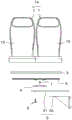
Fig. 1 is a schematic diagram showing an example of the lateral arrangement of seats in a vehicle compartment.
Fig. 2 is a schematic diagram showing an example of the vertical arrangement of seats in the vehicle compartment.
Fig. 3 is an exploded view showing an example of a switching unit to which the present invention is applied.
Fig. 4 is a perspective view showing an example of a linear guide that can be used for the switching unit of the present invention.
Fig. 5 is a perspective view showing a coupling relationship between the seat mounting frame and the rotary support base.
Fig. 6 is a schematic diagram showing a relationship between the linear guide and the seat fixing member.
Fig. 7 is a bottom view showing an example of the rotary support table.
Fig. 8 is a schematic diagram showing the structure of the rotation stop member.
Fig. 9 is a plan view showing the longitudinal arrangement of seats of the switching unit according to the present invention.
Fig. 10 is a plan view showing a first step of changing from the vertical alignment to the horizontal alignment.
Fig. 11 is a plan view showing a second step of changing from the vertical alignment to the horizontal alignment.
Fig. 12 is a plan view showing a third step of changing the vertical alignment to the horizontal alignment.
Detailed Description
Hereinafter, the switching means of the seat arrangement according to the present invention will be described in detail with reference to the drawings.
Fig. 1 and 2 are diagrams showing an arrangement example of seats 1 in a car of a railway vehicle, and show a state where the vehicle is cut at the center in the width direction of the car 2. In both of the arrangements shown in fig. 1 and 2, the seats 1 are provided along the side walls 2a of the vehicle compartment 2, and the center in the width direction of the vehicle compartment 2 is used as a passenger seating space or a passage space. Fig. 1 shows a so-called lateral arrangement, in which the backrest face 10 of the seat 1 is oriented in the direction of travel a or in the opposite direction of travel of the vehicle. On the other hand, fig. 2 shows a so-called longitudinal arrangement in which the backrest surface 10 of the seat 1 is disposed parallel to the traveling direction a of the vehicle.
The seat arrangement switching means of the present invention can change the arrangement of the seats 1 arranged in the lateral arrangement to the longitudinal arrangement, or change the arrangement of the seats 1 arranged in the longitudinal arrangement to the lateral arrangement.
Fig. 3 is a diagram showing an example of a switching unit of the seat arrangement according to the present invention, and the components of the switching unit are shown as an exploded view. The switching unit shown in the figure includes: a support frame 3 fixed to the vehicle body 2 and supporting the seat 1; a rotary support base 4 fixed to the support base 3 and serving as a rotation center of the seat 1; a seat mounting frame 5 for fixing the seat 1; and a linear guide 6 provided along the width direction of the seat 1 and disposed between the seat mounting frame 5 and the rotary support base 4.
In this embodiment, the support frame 3 includes: a substantially L-shaped support member 30 fixed to a side wall of the vehicle compartment; and a base plate 31 supported from below by the support member 30 (see fig. 3). The rotation support table 4 is fixed to the base plate 31. The support frame 3 is formed to protrude from the side wall 2a of the vehicle body 2 toward the center of the vehicle body 2, in order to effectively utilize the space below the seat 1. Therefore, the form of the support frame 3 is not limited to this, and may be, for example, a form fixed to the floor surface of the vehicle compartment 2.
The seat mounting frame 5 is formed long in the width direction of each seat 1 so that a plurality of seats 1 can be arranged in parallel. In this embodiment, the two seats 1 fixed to the seat mounting frame 5 are integrated to form the combination seat 1A, and the arrangement of the combination seats 1A can be changed by the switching means. The number of the seats 1 arranged in parallel on the seat mounting frame 5 is arbitrary, and for example, a combination seat in which three seats are integrated may be configured.
Fig. 4 shows an example of the linear guide 6 fixed to the seat mounting frame 5. The linear guide 6 includes a raceway rail 62 having a rolling surface 61 formed with rolling elements 60 such as balls and rollers along a longitudinal direction thereof, and a moving block 63 linearly movable along the longitudinal direction of the raceway rail 62. The moving block 63 is assembled to the raceway rail 62 via a plurality of rolling elements 60, and an endless circulating path of the rolling elements 60 is provided inside the moving block 63. The moving block 63 can bear all loads acting on a plane orthogonal to the longitudinal direction of the track rail 62 in a state of being assembled to the track rail 62.
As shown in fig. 5, in this embodiment, two linear guides 6 are provided on the seat mounting frame 5, and two rail guides 62 are fixed in parallel to the lower surface side of the seat mounting frame 5. The longitudinal direction of the rail guide 62 coincides with the longitudinal direction of the seat mounting frame 5, that is, the width direction of the combination seat 1A. On the other hand, two moving blocks 63 are assembled to each track rail 62, and these moving blocks 63 are fixed to the rotation support base 4. Therefore, the seat mounting frame 5 is movable in the width direction of the combination seat 1A together with the rail guide 62 with respect to the rotation support base 4.
Further, a seat fixing member 7 is provided on the rotary support base 4, and the seat fixing member 7 locks the movement of the seat mounting frame by the linear guide 6. Fig. 6 is a diagram showing a positional relationship between the seat fixing member 7 and the linear guide 6, and the seat mounting frame and the rotary support table are omitted from illustration. The seat mounting frame 5 is present on the front side of the drawing of fig. 6, and the swivel mount 4 is present on the back side of the drawing.
The seat fixing member 7 is fixed to the rotation support base 4 between two moving blocks 63 assembled to the track rail 62. The seat fixing member 7 includes: a main body 71 having a pressure receiving surface 70 that abuts one side surface of the rail guide 62; a pressing plate 72 that abuts the other side surface of the rail guide 62; and a handle portion 73 screwed to the main body portion 71 to advance and retreat the pressing plate 72 toward the rail guide 62. When the handle portion 73 is rotated to move the pressing plate 72, the rail guide 62 is sandwiched between the pressing plate 72 and the pressure receiving surface 70, and the rail guide 62 is fixed, the movement of the rail guide 62 relative to the rotation support base 4 can be locked. That is, by using the seat fixing member 7, the movement of the seat mounting frame 5 with respect to the rotary support base 4 can be locked, and the seat mounting frame can be fixed at an arbitrary position with respect to the support base.
Fig. 7 shows an example of the rotary support base 4 provided between the support frame 3 and the linear guide 6. The rotary support base 4 includes an inner ring 40 and an outer ring 41 that are rotatable relative to each other, and one of the inner ring 40 and the outer ring 41 is fixed to the base plate 31 of the support base 3, while the other is fixed to the moving block 63 of the linear guide 6. In this embodiment, the inner ring 40 is fixed to the base plate 31, and the outer ring 41 is fixed to the moving block 63. Therefore, the outer ring 41 is provided with a flange portion 41a for fixing the moving block 63, and the flange portion 41a is formed with a plurality of mounting holes 44 for fixing bolts. Further, the main body portion of the seat fixing member 7 is fixed to the flange portion 41a, and a mounting hole 45 for fixing a fixing bolt is formed.
A plurality of rolling elements such as balls and rollers are arranged between the inner ring 40 and the outer ring 41. The outer ring 41 is rotatable relative to the inner ring 40 fixed to the base plate 31 by the rolling elements rolling between the inner ring 40 and the outer ring 41. The rolling element may be made of resin or metal, but from the viewpoint of preventing rattling noise from being generated when vibration acts, a resin rolling element is preferably used. However, when the resin rolling elements are used, it is preferable that the metal rolling elements be mixed in a predetermined ratio with respect to the resin rolling elements from the viewpoint of preventing the separation between the inner ring 40 and the outer ring 41 at the time of overload.
As shown in fig. 8, the rotation preventing member 8 for locking the rotation of the outer ring 41 of the rotation support base 4 with respect to the base plate is provided on the base plate 31. The rotation preventing member 8 includes a stopper pin 80 penetrating the base plate 31, and the stopper pin 80 is constantly biased to the outer race 41 by a coil spring (not shown) incorporated in the rotation preventing member 8. Therefore, the upper end of the stopper pin 80 always protrudes toward the base plate 31. An operating handle 81 is provided at a lower end of the stopper pin 80, and the stopper pin 80 is configured to be buried in the base plate 31 by pulling the operating handle 81 downward. In fig. 8, reference numeral 43 denotes rolling elements arranged between the inner ring 40 and the outer ring 41.
A locking groove 42 is provided on a lower surface side of the outer ring 41 facing the base plate 31, and a tip end of the stopper pin 80 protruding to the base plate 31 is configured to be fitted into the locking groove 42. As shown in fig. 7, the outer ring 41 has a plurality of the locking grooves 42. These locking grooves 42 are provided at predetermined angular intervals around the rotation center of the outer ring 41. In the illustrated example, the locking grooves 42 are provided at four positions at 90-degree intervals, and the outer ring 41 can be fixed at four positions by rotating it 90 degrees with respect to the base plate 31. The position of the locking groove 42 formed with respect to the outer ring 41 is not limited to four positions, and may be provided at eight positions at intervals of 45 degrees, for example, and may be changed as appropriate.
In the seat arrangement switching unit according to the present embodiment configured as described above, the linear bearing 6 and the rotary support base 4 are interposed between the support frame 3 and the seat mounting frame 5, and the seat mounting frame 5 can be moved in the width direction of the combination seat 1A with respect to the support frame 3 by the action of the linear bearing 6, and the seat mounting frame 5 can be rotated with respect to the support frame 3 by the action of the rotary support base 4. That is, by using the combination seat 1A provided in the vehicle cabin 2 of the vehicle by the switching means, the combination seat 1A can be moved in the width direction with respect to the support frame 3, and further, the combination seat 1A can be rotated with respect to the support frame 3, and the arrangement of the seats 1 can be arbitrarily changed in the vehicle cabin 2 by using these functions.
Next, a procedure of changing the arrangement of the seats 1 from the vertical arrangement (see fig. 2) to the horizontal arrangement (see fig. 1) in the vehicle cabin 2 by using the switching means will be described. Fig. 9 is a plan view showing an example in which the seats 1 are arranged in a vertical row along the side wall 2a (shown by a single-dot chain line) in the vehicle compartment 2. The seat 1 is mounted on the switching means so as to form two integrated combination seats 1A. In this vertical arrangement, the backrest surface 10 of each seat 1 faces the center direction of the vehicle compartment 2 (downward in the drawing).
When the arrangement is changed from the vertical arrangement to the horizontal arrangement, first, the gripping of the rail rails 62 by the seat fixing members 7 is released, and the seat mounting frame 5 is allowed to move freely with respect to the rotation support base 4. Then, as shown in fig. 10, the combination seat 1A fixed to the seat mounting frame 5 is moved in the width direction (the direction of arrow B) of the combination seat 1A. Since the linear guide 6 provided between the swivel support base 4 and the seat mounting frame 5 can carry all the load applied in the direction orthogonal to the moving direction of the rail guide 62, the combination seat 1A is held by the support frame 3 without being inclined even if the center of gravity of the combination seat 1A is greatly deviated from the upper side of the swivel support base 4.
After the movement of the combination seat 1A in the width direction is completed, the rotation preventing member 8 is operated to enable the rotation of the inner ring of the rotation support base 4 with respect to the base plate 31, and the seat mounting frame 5 can be rotated with respect to the support base 3. Then, the combination seat 1A fixed to the seat mounting frame 5 is rotated by 90 degrees in the direction of arrow C around the rotation support base 4. As a result of moving the combination seat 1A in the width direction of the combination seat 1A in accordance with the previous procedure, the rotation center of the rotary support table 4 is located in the vicinity of the end portion of the combination seat 1A in the width direction, and even if the combination seat 1A is rotated, the seat 1 itself can be prevented from interfering with the side wall 2a of the vehicle compartment 2. Thereby, the backrest surface 10 of the seat 1 faces the traveling direction or the reverse traveling direction of the vehicle. At this time, a space exists between the rotated seat 1 and the side wall 2a of the vehicle compartment 2.
As shown in fig. 12, when the combination seat 1A is pushed toward the side wall 2a of the vehicle compartment 2 in the direction of the arrow D, the change of the lateral arrangement of the combination seats is completed. In this case, the distance between the side wall 2a of the vehicle compartment 2 and the seat 1 can be arbitrarily set. After the arrangement of the combination seats 1A is changed, the seat mounting frame 5 is fixed to the support frame 3 using the rotation preventing member 8 and the seat fixing member 7.
In the above description, the procedure of changing the combination seat 1A arranged in the vertical direction to the horizontal direction has been described, but the seat group 1A arranged in the horizontal direction may be changed to the vertical direction by the reverse procedure. In this case, since each of the combination seats 1A is movable in the width direction of the seat 1 with respect to the support frame 3, after the vertical arrangement is changed, two adjacent combination seats 1A can be arranged without being separated from each other, and the space in the vehicle compartment can be effectively used.
As described above, if the seat arrangement switching means of the present invention is used, the arrangement of the seats 1 can be easily changed in the passenger compartment of a vehicle such as a railway, a bus, or the like, and after the arrangement change, the seats 1 can be moved in the width direction and fixed at an arbitrary position, so that the convenience in using the seats 1 can be improved.
Claims (3)
1. A seat arrangement switching means for changing the arrangement direction of seats (1) in a vehicle compartment of a vehicle,
the seat arrangement switching means includes:
a support stand (3) that is fixed to the vehicle compartment (2) and supports the seat (1);
a rotary support table (4) that is fixed to the support frame (3) and that serves as the center of rotation of the seat (1);
a seat mounting frame (5) for fixing the seat (1);
a linear guide (6) that is provided along the width direction of the seat (1) with respect to the seat mounting frame (5) and that guides the movement of the seat mounting frame (5) with respect to the swivel support table (4);
a rotation stop member (8) that is provided on the support base (3) and that stops rotation of the seat mounting frame (5) caused by the rotation support base (4); and
and a seat fixing member (7) that locks the movement of the seat mounting frame (5) relative to the rotation support base (4).
2. The switching unit of a seat arrangement according to claim 1,
the rotary support base (4) includes an inner ring and an outer ring rotatably assembled to each other via a plurality of rolling elements, one of the inner ring and the outer ring is fixed to the support base (3), and the other is fixed to the linear guide (6).
3. The switching unit of a seat arrangement according to claim 1,
the linear guide (6) is provided with: a rail fixed to the seat mounting frame (5); and a moving block which is movable in the longitudinal direction of the track rail,
the seat fixing member (7) is provided on the rotary support base (4), and clamps the track rail to lock the movement of the track rail.
Applications Claiming Priority (3)
| Application Number | Priority Date | Filing Date | Title |
|---|---|---|---|
| JP2018169367A JP6672404B2 (en) | 2018-09-11 | 2018-09-11 | Switching unit of seat arrangement |
| JP2018-169367 | 2018-09-11 | ||
| PCT/JP2019/032346 WO2020054329A1 (en) | 2018-09-11 | 2019-08-20 | Seat arrangement switching unit |
Publications (1)
| Publication Number | Publication Date |
|---|---|
| CN112672917A true CN112672917A (en) | 2021-04-16 |
Family
ID=69777990
Family Applications (1)
| Application Number | Title | Priority Date | Filing Date |
|---|---|---|---|
| CN201980059170.8A Pending CN112672917A (en) | 2018-09-11 | 2019-08-20 | Seat arrangement switching unit |
Country Status (4)
| Country | Link |
|---|---|
| EP (1) | EP3851318B1 (en) |
| JP (1) | JP6672404B2 (en) |
| CN (1) | CN112672917A (en) |
| WO (1) | WO2020054329A1 (en) |
Families Citing this family (1)
| Publication number | Priority date | Publication date | Assignee | Title |
|---|---|---|---|---|
| EP4357216A1 (en) * | 2022-10-21 | 2024-04-24 | ALSTOM Holdings | Railway carriage with reconfigurable arrangement of seats |
Citations (7)
| Publication number | Priority date | Publication date | Assignee | Title |
|---|---|---|---|---|
| JPS58129231U (en) * | 1981-10-27 | 1983-09-01 | 天龍工業株式会社 | Rotating piece widening seat |
| DE3707293A1 (en) * | 1987-03-06 | 1988-09-15 | Kiel Gmbh Franz | Double seat, in particular for buses |
| JP4045200B2 (en) * | 2003-03-31 | 2008-02-13 | 天龍工業株式会社 | Vehicle swivel seat |
| CN105460035A (en) * | 2015-12-31 | 2016-04-06 | 今创集团股份有限公司 | Electric rotating mechanism for track traffic seats |
| CN205737024U (en) * | 2015-05-07 | 2016-11-30 | 源捷公司 | Seat alignment system |
| CN206067762U (en) * | 2016-08-31 | 2017-04-05 | 上海坦达轨道车辆座椅系统有限公司 | For the electronic rotation mechanism of rail vehicle seat |
| CN107662525A (en) * | 2016-07-29 | 2018-02-06 | 株式会社瑞延理化 | Seat rotating device for vehicle |
Family Cites Families (9)
| Publication number | Priority date | Publication date | Assignee | Title |
|---|---|---|---|---|
| JPS58126534U (en) * | 1982-02-23 | 1983-08-27 | 富士重工業株式会社 | Rotating seat for bus |
| JPH0264437U (en) * | 1988-11-04 | 1990-05-15 | ||
| US5082328A (en) * | 1990-10-15 | 1992-01-21 | Garelick Richard J | Swivel-slide seat |
| JP3906148B2 (en) | 2002-12-25 | 2007-04-18 | 天龍工業株式会社 | Vehicle seat arrangement switching device |
| US7108325B2 (en) * | 2004-10-08 | 2006-09-19 | B/E Aerospace, Inc. | Movable seat with tapered swivel assembly and cable track wheel |
| WO2007094707A1 (en) * | 2006-02-13 | 2007-08-23 | Volvo Construction Equipment Ab | A vehicle seat mounting device |
| JP2014226964A (en) * | 2013-05-20 | 2014-12-08 | トヨタ車体株式会社 | Seat device for vehicle |
| KR101601507B1 (en) * | 2014-10-17 | 2016-03-08 | 현대자동차주식회사 | Seat for vehicle |
| DE102014224560B4 (en) * | 2014-12-01 | 2022-12-29 | Volkswagen Aktiengesellschaft | Arrangement for a vehicle interior, motor vehicle |
-
2018
- 2018-09-11 JP JP2018169367A patent/JP6672404B2/en active Active
-
2019
- 2019-08-20 CN CN201980059170.8A patent/CN112672917A/en active Pending
- 2019-08-20 WO PCT/JP2019/032346 patent/WO2020054329A1/en unknown
- 2019-08-20 EP EP19859073.9A patent/EP3851318B1/en active Active
Patent Citations (7)
| Publication number | Priority date | Publication date | Assignee | Title |
|---|---|---|---|---|
| JPS58129231U (en) * | 1981-10-27 | 1983-09-01 | 天龍工業株式会社 | Rotating piece widening seat |
| DE3707293A1 (en) * | 1987-03-06 | 1988-09-15 | Kiel Gmbh Franz | Double seat, in particular for buses |
| JP4045200B2 (en) * | 2003-03-31 | 2008-02-13 | 天龍工業株式会社 | Vehicle swivel seat |
| CN205737024U (en) * | 2015-05-07 | 2016-11-30 | 源捷公司 | Seat alignment system |
| CN105460035A (en) * | 2015-12-31 | 2016-04-06 | 今创集团股份有限公司 | Electric rotating mechanism for track traffic seats |
| CN107662525A (en) * | 2016-07-29 | 2018-02-06 | 株式会社瑞延理化 | Seat rotating device for vehicle |
| CN206067762U (en) * | 2016-08-31 | 2017-04-05 | 上海坦达轨道车辆座椅系统有限公司 | For the electronic rotation mechanism of rail vehicle seat |
Also Published As
| Publication number | Publication date |
|---|---|
| EP3851318A4 (en) | 2021-12-15 |
| WO2020054329A1 (en) | 2020-03-19 |
| EP3851318A1 (en) | 2021-07-21 |
| JP6672404B2 (en) | 2020-03-25 |
| EP3851318B1 (en) | 2023-04-26 |
| JP2020040518A (en) | 2020-03-19 |
Similar Documents
| Publication | Publication Date | Title |
|---|---|---|
| CN114080333B (en) | Structure for changing arrangement of seats in vehicle compartment | |
| US3659895A (en) | Swivel seat locking mechanism | |
| US8387936B2 (en) | Slide locking mechanism for seat | |
| US20200086769A1 (en) | Swivel plate assembly | |
| CN106166967B (en) | Center seat stop part control device | |
| US11142097B2 (en) | Track assembly for a vehicle | |
| US11234873B2 (en) | Height adjustable wheelchair docking system | |
| JP2016216032A (en) | Seat mounting apparatus of vehicle | |
| JPS63297195A (en) | Adjustable seat device for aircraft | |
| CN112672917A (en) | Seat arrangement switching unit | |
| US20190135140A1 (en) | Longitudinal adjuster and vehicle seat | |
| US11590913B2 (en) | Restraint monitoring system for a vehicle | |
| US20190241097A1 (en) | Seat support mechanism | |
| CN108284773A (en) | Longitudinal adjuster and seat | |
| EP2977628B1 (en) | Support and guide device | |
| US11731537B2 (en) | Passenger seat assembly with child car seat rail system | |
| JP2018177209A (en) | Apparatus for movement and adjustment of motorcar sheet in longitudinal direction | |
| KR101569190B1 (en) | Automatic track gauge conversion device | |
| CN117621949A (en) | Seat sliding device | |
| CN115884896A (en) | Longitudinally and transversely movable vehicle seat | |
| JP2018099998A (en) | Motion guide apparatus and seat sheet moving and fixing apparatus | |
| US20240308428A1 (en) | Telescopic guide system for sliding steps | |
| CN114901512B (en) | Seating arrangement | |
| JP2016030520A (en) | Vehicle slide rail device | |
| CN117621950A (en) | Seat sliding device |
Legal Events
| Date | Code | Title | Description |
|---|---|---|---|
| PB01 | Publication | ||
| PB01 | Publication | ||
| SE01 | Entry into force of request for substantive examination | ||
| SE01 | Entry into force of request for substantive examination |