CN112661319A - Sewage pretreatment is with transporting soil pick-up car - Google Patents
Sewage pretreatment is with transporting soil pick-up car Download PDFInfo
- Publication number
- CN112661319A CN112661319A CN202110283994.2A CN202110283994A CN112661319A CN 112661319 A CN112661319 A CN 112661319A CN 202110283994 A CN202110283994 A CN 202110283994A CN 112661319 A CN112661319 A CN 112661319A
- Authority
- CN
- China
- Prior art keywords
- chamber
- sewage
- box
- pump
- cavity
- Prior art date
- Legal status (The legal status is an assumption and is not a legal conclusion. Google has not performed a legal analysis and makes no representation as to the accuracy of the status listed.)
- Withdrawn
Links
Images



Landscapes
- Sewage (AREA)
Abstract
The invention discloses a transfer sewage suction truck for sewage pretreatment, which comprises a truck body and a pretreatment assembly arranged on the truck body, wherein the pretreatment assembly comprises a primary pump, a middle-stage pump, a filter box, a sedimentation box, a storage box and a sewage suction pipe; the sedimentation tank is internally provided with a first chamber, a second chamber and a third chamber, a primary sedimentation mechanism is arranged in the first chamber, a middle-level sedimentation mechanism is arranged in the second chamber, a tail end processing mechanism is arranged in the third chamber, a first communicating pipe is arranged between the first chamber and the second chamber, a second communicating pipe is arranged between the second chamber and the third chamber, and a water inlet pipe is arranged between the third chamber and the storage tank. The invention has the advantages of ingenious design and good effect.
Description
Technical Field
The invention relates to the technical field of sewage treatment, in particular to a transfer sewage suction truck for sewage pretreatment.
Background
With the continuous development of the urbanization process, environmental problems, particularly water pollution problems, are one of the hot problems of global concern; the water pollution problem presents a diversified and complicated trend, and the excessive discharge problem caused by the reasons of increased sewage quantity, increased concentration, failure of sewage treatment facilities and the like brings great influence on the environment.
The existing transfer soil pick-up vehicle is suitable for collecting various middle and small-scale dispersible domestic sewage, municipal sewage and similar industrial organic wastewater, but the transfer soil pick-up vehicle only achieves the purpose of transfer, cannot pre-treat the sewage in the transfer process, can only carry out comprehensive treatment after being transferred to a specific place, and cannot effectively utilize the time in the transfer process to carry out the pre-treatment.
Therefore, a transfer soil pick-up vehicle for sewage pretreatment needs to be designed.
Disclosure of Invention
The invention mainly provides a transfer soil pick-up vehicle for sewage pretreatment, which is used for solving the technical problems in the background technology.
The technical scheme adopted by the invention for solving the technical problems is as follows:
a transfer sewage suction truck for sewage pretreatment comprises a truck body and a pretreatment assembly arranged on the truck body, wherein the pretreatment assembly comprises a primary pump, a middle-level pump, a filter box, a settling tank, a storage tank and a sewage suction pipe; the sedimentation tank is internally provided with a first chamber, a second chamber and a third chamber, a primary sedimentation mechanism is arranged in the first chamber, a middle-level sedimentation mechanism is arranged in the second chamber, a tail end processing mechanism is arranged in the third chamber, a first communicating pipe is arranged between the first chamber and the second chamber, a second communicating pipe is arranged between the second chamber and the third chamber, and a water inlet pipe is arranged between the third chamber and the storage tank.
Preferably, the second chamber is located at one side of the first chamber and the third chamber, and the first chamber is located above the third chamber.
Preferably, the primary sedimentation mechanism comprises a first base, a first buffer tank and a first hydraulic cylinder, the first base is arranged at the bottom of the first chamber, a first gap is formed between the first base and the inner wall of the first chamber, the first buffer tank is arranged in the first gap and is in seamless connection with the first base, sewage input into the first sedimentation tank by the intermediate pump can be directly input into the first buffer tank, a first outlet is formed in the wall of the first buffer tank, the lower end of the first outlet is identical to the height of the upper surface of the first base, the first hydraulic cylinder is arranged at the top of the first chamber, and the output end of the first hydraulic cylinder extends into the first chamber and is connected with the first communicating pipe.
Preferably, the middle-level precipitation mechanism comprises an end pump, a second base, a second buffer tank and a second hydraulic cylinder, the second base is arranged at the bottom of the second chamber, a second gap is formed between the second base and the inner wall of the second chamber, the second buffer tank is arranged in the second gap and is in seamless connection with the second base, the second buffer tank, the first communicating pipe and the end pump are connected through a water pipe, the second hydraulic cylinder is arranged at the top of the second chamber, and the output end of the second hydraulic cylinder extends into the second chamber and is connected with the second communicating pipe.
Preferably, the terminal processing mechanism comprises a pump body, a processing layer and a filter screen III, the processing layer is located above the filter screen III, and the pump body is connected with the communicating pipe II.
Preferably, the treatment layer comprises a square frame and two limiting filter screens arranged in the square frame, the two limiting filter screens are arranged up and down, and flocculating agents are placed in spaces in the two limiting filter screens.
Preferably, the upper surface of automobile body is all located to elementary pump, intermediate pump, rose box, settling tank, the bottom of automobile body is located to the bin, the upper end and the three intercommunications of cavity of inlet tube, the lower extreme of inlet tube run through the automobile body and communicate with the bin, be equipped with the solenoid valve on the inlet tube.
Preferably, the filter assembly comprises a first filter screen and a second filter screen which are arranged up and down, the aperture of the first filter screen is larger than that of the second filter screen, and the first filter screen is located below the water inlet.
Compared with the prior art, the invention has the beneficial effects that:
one is as follows: according to the sewage treatment device, the sewage pumped out of the sewage suction pipe can be primarily filtered through the filtering component, and impurities with large volume are filtered, so that the sewage can be conveniently pretreated at the later stage, and the time is saved.
The second step is as follows: the invention can carry out primary sedimentation and secondary sedimentation on the sewage filtered by the filtering component by arranging the primary sedimentation mechanism, the middle-stage sedimentation mechanism and the tail end treatment mechanism, and finally carry out final treatment by the tail end treatment mechanism, thereby achieving the aim of whole pretreatment.
The present invention will be explained in detail below with reference to the drawings and specific embodiments.
Drawings
FIG. 1: the invention has a structure schematic diagram.
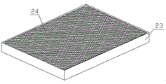
FIG. 2: the structure of the treatment layer of the invention is schematically shown.
FIG. 3: the invention is shown in the structural diagram A.
FIG. 4: the invention discloses a relation schematic diagram between a first buffer box and a first base.
In the figure: 1. the device comprises a vehicle body, 2, a primary pump, 3, a middle-stage pump, 4, a filter box, 5, a settling tank, 6, a storage tank, 7, a sewage suction pipe, 8, a first chamber, 9, a second chamber, 10, a third chamber, 11, a water inlet pipe, 12, a first base, 13, a first buffer tank, 14, a first hydraulic cylinder, 15, a first communicating pipe, 16, a second communicating pipe, 17, a tail-end pump, 18, a second base, 19, a second buffer tank, 20, a second hydraulic cylinder, 21, a processing layer, 22, a third filter screen, 23, a square frame, 24, a limiting filter screen, 25, a first filter screen, 26, a second filter screen, 27 and a first outlet.
Detailed Description
In order to facilitate an understanding of the invention, the invention will now be described more fully hereinafter with reference to the accompanying drawings, in which several embodiments of the invention are shown, but which may be embodied in different forms and not limited to the embodiments described herein, but which are provided so as to provide a more thorough and complete disclosure of the invention.
It will be understood that when an element is referred to as being "secured to" another element, it can be directly on the other element or intervening elements may be present, and when an element is referred to as being "connected" to another element, it can be directly connected to the other element or intervening elements may also be present, as the terms "vertical", "horizontal", "left", "right" and the like are used herein for descriptive purposes only.
Unless defined otherwise, all technical and scientific terms used herein have the same meaning as commonly understood by one of ordinary skill in the art to which this invention belongs, and the knowledge of the terms used herein in the specification of the present invention is for the purpose of describing particular embodiments and is not intended to limit the present invention, and the term "and/or" as used herein includes any and all combinations of one or more of the associated listed items.
Referring to fig. 1 to 4, the invention provides a transfer sewage suction truck for sewage pretreatment, which comprises a truck body 1 and a pretreatment module arranged on the truck body 1, wherein the pretreatment module comprises a primary pump 2, a middle-stage pump 3, a filter tank 4, a settling tank 5, a storage tank 6 and a sewage suction pipe 7, the primary pump 2, the middle-stage pump 3, the filter tank 4 and the settling tank 5 are all arranged on the upper surface of the truck body 1, and the storage tank 6 is arranged at the bottom of the truck body 1.
Referring to fig. 1, a filter assembly is arranged in the filter box 4, a water inlet and a water outlet are arranged on the filter box 4, the sewage suction pipe 7 and the water inlet are both connected with the primary pump 2 through water pipes, the filter assembly comprises a first filter screen 25 and a second filter screen 26 which are arranged up and down, the aperture of the first filter screen 25 is larger than that of the second filter screen 26, the first filter screen 25 is located below the water inlet, sewage pumped from the sewage suction pipe 7 can be filtered by the first filter screen 25 and the second filter screen 26, and some impurities with large volume are filtered. Because all be connected with the intermediate pump 3 through the water pipe between delivery port and the setting tank 5, consequently the sewage after the filtration can pass through the intermediate pump 3 and get into in the setting tank 5.
Please refer to fig. 1 again, a first chamber 8, a second chamber 9 and a third chamber 10 are arranged in the settling tank 5, the second chamber 9 is located at one side of the first chamber 8 and the third chamber 10, the first chamber 8 is located above the third chamber 10, a primary settling mechanism is arranged in the first chamber 8, a middle settling mechanism is arranged in the second chamber 9, a tail end processing mechanism is arranged in the third chamber 10, a first communicating pipe 15 is arranged between the first chamber 8 and the second chamber 9, and a second communicating pipe 16 is arranged between the second chamber 9 and the third chamber 10.
The primary sedimentation mechanism comprises a first base 12, a first buffer tank 13 and a first hydraulic cylinder 14, wherein the first base 12 is arranged at the bottom of a first chamber 8, a first gap is formed between the first base 12 and the inner wall of the first chamber 8, the first buffer tank 13 is arranged in the first gap and is in seamless connection with the first base 12, sewage input into the first sedimentation tank 5 through the middle-stage pump 3 can be directly input into the first buffer tank 13, a first outlet 27 is formed in the wall of the first buffer tank 13, the lower end of the first outlet 27 is identical to the height of the upper surface of the first base 12, the first hydraulic cylinder 14 is arranged at the top of the first chamber 8, and the output end of the first hydraulic cylinder 14 extends into the first chamber 8 and is connected with a first communicating pipe 15.
Referring to fig. 1 and 4, the middle-stage precipitation mechanism includes a tail-end pump 17, a second base 18, a second buffer tank 19 and a second hydraulic cylinder 20, the second base 18 is disposed at the bottom of the second chamber 9, a second gap is disposed between the second base 18 and the inner wall of the second chamber 9, the second buffer tank 19 is disposed in the second gap and is in seamless connection with the second base 18, a second outlet is disposed on the wall of the second buffer tank 19, the lower end of the second outlet is as high as the upper surface of the second base 18, the second buffer tank 19, the first communication pipe 15 and the tail-end pump 17 are all connected through a water pipe, the second hydraulic cylinder 20 is disposed at the top of the second chamber 9, and the output end of the second hydraulic cylinder 20 extends into the second chamber 9 and is connected with the second communication pipe 16.
Referring to fig. 1, 2 and 3, the end processing mechanism includes a pump body 28, a processing layer 21 and a filter screen three 22, the processing layer 21 is located above the filter screen three 22, and the pump body 28 is connected to the second communication pipe 16. The treatment layer 21 comprises a frame 23 and two limiting filter screens 24 arranged in the frame 23, the two limiting filter screens 24 are arranged up and down, flocculating agents are placed in the spaces in the two limiting filter screens 24, sewage in the second chamber 9 can enter the third chamber 10 through the communicating pipe 16, the sewage at the moment can be fused with the flocculating agents between the two limiting filter screens 24 to form flocculates, and the smaller flocculates are filtered out through the third filter screen 22.
Referring to fig. 1, a water inlet pipe 11 is disposed between the chamber three 10 and the storage box 6, an upper end of the water inlet pipe 11 is communicated with the chamber three 10, a lower end of the water inlet pipe 11 penetrates through the vehicle body 1 and is communicated with the storage box 6, and an electromagnetic valve is disposed on the water inlet pipe 11.
The working principle of the embodiment is as follows:
the sewage is sucked into the filter tank 4 from the sewage suction pipe 7 by starting the primary pump 2 and is respectively filtered by the first filter screen 25 and the second filter screen 26, so that some impurities with large volume are filtered, and then directly enter the first buffer tank 13 through the middle-stage pump 3.
Because the lower end of the first outlet 27 is as high as the upper surface of the first base 12, the sewage entering the first buffer tank 13 slowly overflows from the first outlet 27, so that the fine impurities in the sewage are conveniently precipitated. After a period of precipitation, tiny impurity in the sewage can precipitate, and a comparatively clear sewage accessible control pneumatic cylinder 14 for a communicating pipe 15 descends to suitable position, through opening end pump 17, takes away comparatively clear sewage, can prevent that a communicating pipe 15 from taking away the tiny impurity that deposits like this, and this kind of mode is comparatively gentle.
The cleaner sewage is pumped into the second buffer tank 19 through the end pump 17, and the second buffer tank 19 has the same function as the first buffer tank 13, and is also used for slowly overflowing the cleaner sewage through the second outlet and then precipitating the cleaner sewage in the second chamber 9.
Through the pump body 28, the relatively clear sewage after the second time of precipitation in the second chamber 9 is pumped into the third chamber 10, then the sewage is treated by the flocculating agent between the two limiting filter screens 24, then the relatively clear sewage is introduced into the storage tank 6 through the water inlet pipe 11 to be stored, and then the vehicle body 1 is driven to a fixed point to be treated.
The invention has been described above with reference to the accompanying drawings, and it is obvious that the invention is not limited to the specific implementation in the above-described manner, and it is within the scope of the invention to adopt such insubstantial modifications of the inventive method concept and solution, or to apply the inventive concept and solution directly to other applications without such modifications.
Claims (8)
1. The utility model provides a sewage pretreatment is with transporting soil pick-up car which characterized in that: the device comprises a vehicle body (1) and a pretreatment assembly arranged on the vehicle body (1), wherein the pretreatment assembly comprises a primary pump (2), a middle-stage pump (3), a filter box (4), a sedimentation box (5), a storage box (6) and a sewage suction pipe (7), the filter assembly is arranged in the filter box (4), the filter box (4) is provided with a water inlet and a water outlet, the sewage suction pipe (7) and the water inlet are both connected with the primary pump (2) through water pipes, and the water outlet and the sedimentation box (5) are both connected with the middle-stage pump (3) through water pipes; be equipped with cavity one (8), cavity two (9), cavity three (10) in precipitation case (5), be equipped with elementary precipitation mechanism in cavity one (8), be equipped with the intermediate level in cavity two (9) and deposit the mechanism, be equipped with terminal processing mechanism in cavity three (10), be equipped with communicating pipe one (15) between cavity one (8) and cavity two (9), be equipped with communicating pipe two (16) between cavity two (9) and cavity three (10), be equipped with inlet tube (11) between cavity three (10) and bin (6).
2. The transfer soil pick-up cart for sewage pretreatment of claim 1, wherein: the second chamber (9) is positioned at one side of the first chamber (8) and the third chamber (10), and the first chamber (8) is positioned above the third chamber (10).
3. The transfer soil pick-up cart for sewage pretreatment of claim 2, wherein: elementary sediment mechanism is including base (12), baffle-box (13), pneumatic cylinder (14), establish the bottom in chamber (8) base (12), be equipped with clearance one between the inner wall of base (12) and chamber (8), in clearance one and base (12) seamless connection are located in buffer-box (13), through in sewage that intermediate pump (3) input to in precipitation box (5) can directly be defeated into baffle-box (13), export one (27) have been seted up on the tank wall of baffle-box (13), the lower extreme of export one (27) is the same with the upper surface height of base (12), the top of chamber (8) is located to pneumatic cylinder (14), the output of pneumatic cylinder (14) stretches into in chamber (8) and is connected between communicating pipe (15).
4. The transfer soil pick-up cart for sewage pretreatment of claim 1, wherein: middle-level precipitation mechanism is including end pump (17), second base (18), second buffer tank (19), second pneumatic cylinder (20), the bottom in second chamber (9) is established in second base (18), be equipped with second clearance between the inner wall of second base (18) and second chamber (9), second buffer tank (19) locate in second clearance and with seamless connection between second base (18), export two has been seted up on the tank wall of second buffer tank (19), the lower extreme of export two is the same with the upper surface height of second base (18), all through water piping connection between second buffer tank (19), communicating pipe (15) and end pump (17), the top of second chamber (9) is located in second pneumatic cylinder (20), the output of second pneumatic cylinder (20) stretch into in second chamber (9) and with be connected between second communicating pipe (16).
5. The transfer soil pick-up cart for sewage pretreatment of claim 4, wherein: the tail end processing mechanism comprises a pump body (28), a processing layer (21) and a filter screen III (22), the processing layer (21) is located above the filter screen III (22), and the pump body (28) is connected with a communicating pipe II (16).
6. The transfer soil pick-up cart for sewage pretreatment of claim 5, wherein: the treatment layer (21) comprises a square frame (23) and two limiting filter screens (24) arranged in the square frame (23), the two limiting filter screens (24) are arranged up and down, and flocculating agents are placed in spaces in the limiting filter screens (24).
7. The transfer soil pick-up cart for sewage pretreatment of claim 1, wherein: the upper surface of automobile body (1) is all located in elementary pump (2), intermediate pump (3), rose box (4), setting tank (5), the bottom of automobile body (1) is located in bin (6), the upper end and the three (10) intercommunications of cavity of inlet tube (11), the lower extreme of inlet tube (11) run through automobile body (1) and communicate with bin (6), be equipped with the solenoid valve on inlet tube (11).
8. The transfer soil pick-up cart for sewage pretreatment of claim 1, wherein: the filter assembly comprises a first filter screen (25) and a second filter screen (26), the first filter screen (25) and the second filter screen (26) are arranged up and down, the aperture of the first filter screen (25) is larger than that of the second filter screen (26), and the first filter screen (25) is located below the water inlet.
Priority Applications (1)
| Application Number | Priority Date | Filing Date | Title |
|---|---|---|---|
| CN202110283994.2A CN112661319A (en) | 2021-03-17 | 2021-03-17 | Sewage pretreatment is with transporting soil pick-up car |
Applications Claiming Priority (1)
| Application Number | Priority Date | Filing Date | Title |
|---|---|---|---|
| CN202110283994.2A CN112661319A (en) | 2021-03-17 | 2021-03-17 | Sewage pretreatment is with transporting soil pick-up car |
Publications (1)
| Publication Number | Publication Date |
|---|---|
| CN112661319A true CN112661319A (en) | 2021-04-16 |
Family
ID=75399584
Family Applications (1)
| Application Number | Title | Priority Date | Filing Date |
|---|---|---|---|
| CN202110283994.2A Withdrawn CN112661319A (en) | 2021-03-17 | 2021-03-17 | Sewage pretreatment is with transporting soil pick-up car |
Country Status (1)
| Country | Link |
|---|---|
| CN (1) | CN112661319A (en) |
Citations (6)
| Publication number | Priority date | Publication date | Assignee | Title |
|---|---|---|---|---|
| US6361701B1 (en) * | 1996-12-23 | 2002-03-26 | Horst Schade | Method and device for continuous filtration of liquids |
| CN101077497A (en) * | 2006-05-22 | 2007-11-28 | 江苏安特汽车制造有限公司 | Sewage water cycling and reutilization type pipeline dredging soil pick-up vehicle |
| CN103895554A (en) * | 2014-04-16 | 2014-07-02 | 武汉理工大学 | Automobile special for sewer sewage treatment and sewage recycling method thereof |
| CN103908832A (en) * | 2014-04-18 | 2014-07-09 | 武汉理工大学 | Multi-stage sewage treatment recycling system of suction-type sewer scavenger |
| JP2019013904A (en) * | 2017-07-10 | 2019-01-31 | 新虎興産株式会社 | Asbestos-containing sewage disposal apparatus |
| CN110713329A (en) * | 2019-11-15 | 2020-01-21 | 嘉兴汇昌塑业有限公司 | Plastic septic tank capable of separating mud from water |
-
2021
- 2021-03-17 CN CN202110283994.2A patent/CN112661319A/en not_active Withdrawn
Patent Citations (6)
| Publication number | Priority date | Publication date | Assignee | Title |
|---|---|---|---|---|
| US6361701B1 (en) * | 1996-12-23 | 2002-03-26 | Horst Schade | Method and device for continuous filtration of liquids |
| CN101077497A (en) * | 2006-05-22 | 2007-11-28 | 江苏安特汽车制造有限公司 | Sewage water cycling and reutilization type pipeline dredging soil pick-up vehicle |
| CN103895554A (en) * | 2014-04-16 | 2014-07-02 | 武汉理工大学 | Automobile special for sewer sewage treatment and sewage recycling method thereof |
| CN103908832A (en) * | 2014-04-18 | 2014-07-09 | 武汉理工大学 | Multi-stage sewage treatment recycling system of suction-type sewer scavenger |
| JP2019013904A (en) * | 2017-07-10 | 2019-01-31 | 新虎興産株式会社 | Asbestos-containing sewage disposal apparatus |
| CN110713329A (en) * | 2019-11-15 | 2020-01-21 | 嘉兴汇昌塑业有限公司 | Plastic septic tank capable of separating mud from water |
Similar Documents
| Publication | Publication Date | Title |
|---|---|---|
| CN112661319A (en) | Sewage pretreatment is with transporting soil pick-up car | |
| CN110183068A (en) | A kind of food and drink waste water integration advanced treatment reactor | |
| CN102432119B (en) | Sewage and waste acid treatment device and treatment process | |
| CN217921786U (en) | Municipal domestic sewage treatment system | |
| CN206328249U (en) | Heavy metal waste water treatment system | |
| CN215480434U (en) | Device for preparing derived fuel by modifying mixed sludge through quenching and tempering and high-pressure dehydration | |
| CN116750897A (en) | Circulating water treatment device for car washer | |
| CN214243985U (en) | Anti-sedimentation mine water purification treatment system | |
| CN108706840A (en) | A kind of laboratory waste water integrated treatment unit | |
| CN201415072Y (en) | Pulp thickening system capable of increasing pulp density | |
| WO2022204826A1 (en) | Bioreactor wastewater treatment apparatus | |
| CN208500567U (en) | Rare Earth Separation processing waste water processing equipment | |
| CN209685553U (en) | A kind of domestic sludge enrichment facility | |
| CN205328761U (en) | Carwash water processing system | |
| CN207760129U (en) | A kind of Self-help car washer wastewater from car washer recycling and processing equipment | |
| CN205659445U (en) | Electroplate cyanide wastewater filtration system | |
| CN205419939U (en) | Chemical industry waste liquid classification recovery device | |
| CN216584531U (en) | PTFE suspension washing wastewater recycling system | |
| CN206428127U (en) | A kind of printing and dyeing wastewater processing equipment | |
| CN205270240U (en) | Washing is retrieved and is applied mechanically device | |
| CN107456786A (en) | A kind of electroplating cyanic waste water filtration system | |
| CN108423875A (en) | Rare Earth Separation processing waste water processing equipment and its processing method | |
| CN221777711U (en) | Circulating sewage treatment equipment | |
| CN213596063U (en) | Wastewater treatment device for efficiently filtering phosphorus and nitrogen | |
| CN216946473U (en) | Automatic change water treatment facilities |
Legal Events
| Date | Code | Title | Description |
|---|---|---|---|
| PB01 | Publication | ||
| PB01 | Publication | ||
| SE01 | Entry into force of request for substantive examination | ||
| SE01 | Entry into force of request for substantive examination | ||
| WW01 | Invention patent application withdrawn after publication | ||
| WW01 | Invention patent application withdrawn after publication |
Application publication date: 20210416 |