JP2019013904A - Asbestos-containing wastewater treatment equipment - Google Patents
Asbestos-containing wastewater treatment equipment Download PDFInfo
- Publication number
- JP2019013904A JP2019013904A JP2017135016A JP2017135016A JP2019013904A JP 2019013904 A JP2019013904 A JP 2019013904A JP 2017135016 A JP2017135016 A JP 2017135016A JP 2017135016 A JP2017135016 A JP 2017135016A JP 2019013904 A JP2019013904 A JP 2019013904A
- Authority
- JP
- Japan
- Prior art keywords
- sewage
- water
- air
- tank
- filter
- Prior art date
- Legal status (The legal status is an assumption and is not a legal conclusion. Google has not performed a legal analysis and makes no representation as to the accuracy of the status listed.)
- Granted
Links
Images



Landscapes
- Degasification And Air Bubble Elimination (AREA)
- Separation Of Suspended Particles By Flocculating Agents (AREA)
- Separation Of Particles Using Liquids (AREA)
- Filtration Of Liquid (AREA)
- Working Measures On Existing Buildindgs (AREA)
Abstract
【課題】アスベストを含む汚水および吸引に使用した空気からアスベストやその他の廃棄物を取り除き、排気・放流できる程度に空気や水を浄化することのできる汚水処理装置を提供する。【解決手段】汚水処理装置10を、アスベストを含む汚水を空気とともに吸引する真空吸引機20と、汚水と空気とを互いに分離する遠心分離器40と、遠心分離器40で分離された空気を浄化する空気浄化槽30と、遠心分離器40で分離された汚水をろ過フィルタ56でろ過する汚水分離槽50と、汚水分離槽50でろ過された汚水を凝集沈殿処理する凝集沈殿槽70と、凝集沈殿処理した後の上澄み水をろ過する水フィルタ80と、水フィルタ80でろ過した上澄み水をpH調整剤Pで水質調整した後、放流するpH調整槽90とで構成し、ろ過フィルタ56としてフレキシブルコンテナバッグを使用することにより、上記課題を解決できる。【選択図】図1PROBLEM TO BE SOLVED: To provide a sewage treatment device capable of removing asbestos and other wastes from sewage containing asbestos and air used for suction, and purifying the air and water to the extent that they can be exhausted and discharged. SOLUTION: A sewage treatment device 10 purifies a vacuum suction machine 20 that sucks sewage containing asbestos together with air, a centrifuge 40 that separates sewage and air from each other, and air separated by the centrifuge 40. An air septic tank 30 to be used, a sewage separation tank 50 that filters sewage separated by a centrifuge 40 with a filtration filter 56, a coagulation sedimentation tank 70 that coagulates and precipitates sewage filtered by the sewage separation tank 50, and coagulation sedimentation. It is composed of a water filter 80 that filters the supernatant water after treatment and a pH adjustment tank 90 that discharges the supernatant water filtered by the water filter 80 after adjusting the water quality with the pH adjuster P, and serves as a flexible container as the filtration filter 56. The above problem can be solved by using the bag. [Selection diagram] Fig. 1
Description
本発明は、古い建物等を解体する際等において、外壁等に吹き付けられたアスベスト含有塗膜等の除去作業に使用されたアスベスト含有汚水を処理する装置に関する。 The present invention relates to an apparatus for treating asbestos-containing sewage used for removing asbestos-containing coating film or the like sprayed on an outer wall or the like when dismantling an old building or the like.
防火性や絶縁性に優れていることから、過去、建築用の材料等として広く使用されていたアスベストは、その後、劣化または損傷してアスベスト繊維が空気中に飛散したときに、建築物の使用者や工事従業者等の健康に悪影響を与えることがわかり、現在は使用が禁止されていると共に、アスベストが使用されていた古い建物等を解体する際等においては、アスベスト繊維が飛散しないようにする厳重な対策が求められている。 Asbestos, which has been widely used as a building material in the past due to its excellent fireproofing and insulating properties, was used after the deterioration or damage of the asbestos fibers in the air. It is known that it will adversely affect the health of workers and construction workers, etc., and is now prohibited from use, and when disassembling old buildings where asbestos was used, asbestos fibers should not be scattered Strict countermeasures are required.
アスベスト繊維の飛散を防止するための対策技術が特許文献1に開示されている。特許文献1に開示された技術は、建物等の壁や鉄骨に吹き付けられたアスベストに飛散防止剤を吹き付けた後、建設用機械等を用いてアスベストを除去するようになっている。また、アスベストを機械的に除去することによって新たに露出する部分にも飛散防止剤を吹き付けるようになっている。
このように、特許文献1に開示された技術によれば、飛散防止剤を吹き付けることによってアスベスト繊維が空気中に飛散することを防止できるとされている。
Thus, according to the technique disclosed in
しかし、特許文献1に開示された技術であっても、壁や鉄骨に吹き付けられた状態のアスベストに対して飛散防止剤を吹き付けるときや、機械的に除去されたアスベストの新たに露出した部分から空気中にアスベスト繊維が飛散することを完全に防止することはできない。このため、特許文献1に開示された「飛散防止剤を吹き付ける」技術を使用できるのは、空気中に飛散したアスベスト繊維を外部に漏れ出さないようにする対策を取ることができる室内作業か、あるいは、アスベストを除去する領域を完全に囲うことができるような作業環境下に限定される。
However, even with the technique disclosed in
特許文献1に開示された技術が抱えている上述のような問題に対応するため、高圧水を噴射することによって建物等の壁や鉄骨に吹き付けられたアスベストを除去し、これと同時に除去後のアスベストを含む汚水を真空吸引することにより、アスベスト繊維が空気中に飛散するおそれを極小化する技術が開発されている。
In order to cope with the above-mentioned problems that the technology disclosed in
しかしながら、アスベストを含む汚水を吸引する技術にも問題があった。すなわち、吸引後の汚水は産業廃棄物としての管理が求められることから放流することはできず、アスベストの除去処理を行う度に管理すべき汚水の量が増えていくという問題があった。 However, there is a problem with the technique for sucking sewage containing asbestos. That is, the sewage after suction cannot be discharged because management as industrial waste is required, and there is a problem that the amount of sewage to be managed increases every time asbestos is removed.
本発明は、このような従来技術の問題に鑑みて開発されたものである。それゆえに本発明の主たる課題は、吸引されたアスベストを含む汚水および吸引に使用した空気からアスベストやその他の廃棄物を取り除き、排気・放流できる程度に空気や水を浄化することのできる汚水処理装置を提供することにある。 The present invention has been developed in view of such problems of the prior art. Therefore, the main object of the present invention is to remove the asbestos and other wastes from the sewage containing the asbestos and the air used for the suction, and to purify the air and water to such an extent that they can be exhausted and discharged. Is to provide.
(1)
本発明の一局面によれば、
アスベストを含む汚水を空気とともに吸引する真空吸引機と、
前記汚水と前記空気とを互いに分離する遠心分離器と、
前記遠心分離器と前記真空吸引機との間において、前記遠心分離器で分離された前記空気を浄化する空気浄化槽と、
前記遠心分離器で分離された前記汚水をろ過フィルタでろ過する汚水分離槽と、
前記汚水分離槽でろ過された前記汚水を凝集沈殿処理する凝集沈殿槽と、
凝集沈殿処理した後の上澄み水をろ過する水フィルタ材を有する水フィルタと、
前記水フィルタでろ過した前記上澄み水をpH調整剤で水質調整した後、放流するpH調整槽とを備える汚水処理装置において、
前記ろ過フィルタとして、フレキシブルコンテナバッグが使用されていることを特徴とする汚水処理装置が提供される。
(1)
According to one aspect of the present invention,
A vacuum suction machine for sucking sewage containing asbestos together with air;
A centrifuge for separating the sewage and the air from each other;
An air purification tank for purifying the air separated by the centrifugal separator between the centrifugal separator and the vacuum suction device;
A sewage separation tank for filtering the sewage separated by the centrifuge with a filtration filter;
A coagulation sedimentation tank for coagulating and precipitating the sewage filtered in the sewage separation tank;
A water filter having a water filter material for filtering the supernatant water after the coagulation sedimentation treatment;
In the sewage treatment apparatus comprising a pH adjustment tank to be discharged after adjusting the water quality of the supernatant water filtered by the water filter with a pH adjuster,
A sewage treatment apparatus is provided in which a flexible container bag is used as the filtration filter.
(2)
好適には、前記水フィルタ材は、3層のカートリッジフィルタで構成されている
(2)
Preferably, the water filter material is constituted by a three-layer cartridge filter.
(3)
好適には、3層のカートリッジフィルタは、上流側から下流側に向けて順に目が細かくなるように配置されている
(3)
Preferably, the three-layer cartridge filter is arranged so that the meshes become finer in order from the upstream side to the downstream side.
本発明によれば、吸引されたアスベストを含む汚水および吸引に使用した空気からアスベストやその他の廃棄物を取り除き、排気・放流できる程度に空気や水を浄化することができる汚水処理装置を提供できる。 ADVANTAGE OF THE INVENTION According to this invention, the sewage treatment apparatus which can purify air and water to such an extent that asbestos and other wastes are removed from the sewage containing the asbestos sucked and the air used for suction can be provided. .
(汚水処理装置10の構成)
以下、本発明が適用された汚水処理装置10の実施例について説明する。この汚水処理装置10は、図1に示すように、大略、真空吸引機20と、空気浄化槽30と、遠心分離器40と、汚水分離槽50と、汚水貯留槽60と、凝集沈殿槽70と、水フィルタ80と、pH調整槽90と、沈殿物ろ過槽110とで構成されている。
(Configuration of sewage treatment apparatus 10)
Hereinafter, the Example of the
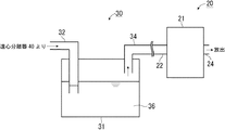
真空吸引機20は、図2に示すように、真空吸引機本体21、吸引口22、および排気口24を備えており、真空吸引機20を動作させることにより、主として空気を吸引口22から吸い込み、排気口24から吐き出すようになっている。
As shown in FIG. 2, the
空気浄化槽30は、空気浄化槽本体31、吸気管32、および、排気管34を備えており、排気管34が真空吸引機20の吸引口22に取り付けられている。空気浄化槽30は、真空吸引機20によって吸引された空気を空気浄化槽本体31に設けられた吸気管32から取り入れ、この空気中に含まれる微量の埃(塗膜等も含む)やアスベスト等を空気浄化槽本体31に溜められた浄化用水36で捕捉する役割を有している。
The
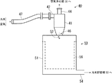
遠心分離器40は、図3に示すように、建物解体現場等で発生するアスベスト、水、および、その他の廃棄物(例えば、塗装膜)が混ざった汚水を空気とともに吸引し、内部でこれら汚水および空気に遠心力を付与することにより比重の大きい汚水と、汚水よりも比重の小さい空気とを分離する装置である。この遠心分離器40は、遠心分離器本体41と、この遠心分離器本体41に設けられた吸引口42、排気口44、および汚水排出口46とを備えている。
As shown in FIG. 3, the
また、遠心分離器本体41の排気口44は、空気浄化槽30の吸気管32に接続されている。また、吸引口42には、建物解体現場等において汚水を空気とともに吸引する吸引具47が接続されている。なお、この吸引具47には、現場の状況に合わせた適切な長さ・径のパイプやホース等が使用される。
Further, the
これにより、吸引具47で吸引された汚水および空気は遠心分離器本体41に入り、汚水から分離された空気が排気口44から排気されるとともに、空気から分離された汚水が汚水排出口46から排出される。
As a result, the sewage and air sucked by the
汚水分離槽50は、遠心分離器40で空気から分離された汚水を受け入れる槽であり、汚水分離槽本体51と、この汚水分離槽本体51に設けられた汚水受入口52および排水口54とを備えている。さらに、汚水分離槽本体51の内側には汚水中に含まれる比較的粗いもの(例えば、粗い塗膜片やゴミなど)をろ過するろ過フィルタ56が設けられている。このろ過フィルタ56としては、例えば、フレキシブルコンテナバッグを使用することができる。
The
汚水受入口52は、汚水分離槽本体51の天面あるいは上方側面に設けられており、遠心分離器40の汚水排出口46に接続されている。これにより、汚水排出口46から排出された汚水が汚水受入口52を介して汚水分離槽本体51内に受け入れられる。
The
排水口54は汚水分離槽本体51の底面あるいは下方側面に設けられている。汚水分離槽本体51に受け入れられた後、ろ過フィルタ56でろ過された汚水がこの排水口54から排出される。
The
汚水貯留槽60は、図4に示すように、汚水分離槽50から排出された汚水を受け入れて、汚水中に含まれる水よりも比重の大きいものを自然沈殿させる水槽である。この汚水貯留槽60は、汚水貯留槽本体61と、汚水貯留槽本体61内に貯留された上澄み汚水を凝集沈殿槽70に送る第1水中ポンプ62とを備えている。
As shown in FIG. 4, the
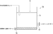
凝集沈殿槽70は、図5に示すように、汚水貯留槽60から受け入れた汚水に含まれる水以外の成分を凝集沈殿させる役割を有している。この凝集沈殿槽70は、凝集沈殿槽本体71と、凝集沈殿処理後の上澄み水を水フィルタ80に送る排水口72と、沈殿物を沈殿物ろ過槽110に送る沈殿物排出口74とを備えている。
As shown in FIG. 5, the
凝集沈殿槽本体71に貯留された汚水に凝集沈殿剤Gが投入されることにより、汚水に含まれていた不純物が凝集沈殿槽本体71の底に沈殿する。不純物を沈殿させた後の上澄み水は、排水口72から水フィルタ80へ送られる。また、沈殿物は沈殿物排出口74から沈殿物ろ過槽110へ送られる。
By introducing the coagulating sedimentation agent G into the sewage stored in the coagulation sedimentation tank
凝集沈殿槽70で使用される凝集沈殿剤Gとしては、例えばエコマックス社のTW−20WKが使用される。凝集沈殿剤Gは、当該凝集沈殿剤Gとの化学反応で汚水をフロック状にすることを目的として使用される。凝集沈殿剤Gの使用量は、フロックが1cm前後の大きさとなるように、汚水の質に応じて決定される。具体的には、汚水の質を目視して凝集沈殿剤Gを投入するタイマー時間を設定し、凝集沈殿剤Gの点滴量を調整する。なお、上記の目的を達成できるのであれば、どのような種類の凝集沈殿剤Gを使用してもよく、かつ、その使用量も適宜決定される。
As the coagulation sedimentation agent G used in the
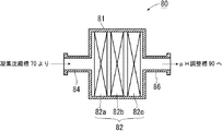
水フィルタ80は、図6に示すように、凝集沈殿槽70から送られてきた上澄み水をろ過して、特にアスベストを捕捉する役割を有するフィルタである。水フィルタ80は、水フィルタ本体81と、水フィルタ材82とを備えており、水フィルタ本体81には、一次口84および二次口86が設けられている。
As shown in FIG. 6, the
水フィルタ本体81の一次口84は、凝集沈殿槽70の排水口72に接続されており、排水口72から送られてきた上澄み水は一次口84を介して水フィルタ本体81内に入り、水フィルタ材82でろ過された後、二次口86を通ってpH調整槽90に送られる。
The
なお、水フィルタ材82は、3層のカートリッジフィルタ82a,82b,82cで構成されている。各カートリッジフィルタ82a,82b,82cには、例えば、ポリプロピレン製糸巻きカートリッジが使用されるがこれに限定されるものではない。また、各カートリッジフィルタ82a,82b,82cのろ過粒度はそれぞれ20μm、10μm、および、1μmであり、目の粗い(20μm)カートリッジフィルタ82aが上流側に配置され、目の細かい(1μm)カートリッジフィルタ82cが下流側に配置されている。中程度の粗さ(10μm)のカートリッジフィルタ82bは中段に配置されている。
The
このように、上流側から下流側に向けて順に目が細かくなるようにカートリッジフィルタを配置しておくことで、水フィルタ80のろ過能力を高めることができるとともに、目詰まりしやすい粒度のカートリッジフィルタだけを交換すれば安価にろ過能力を回復できる。なお、水フィルタ材82として使用するカートリッジフィルタの数は3層に限定されるものではなく、1層でもよいし、2層あるいは4層以上であってもよい。また、複数枚のカートリッジフィルタを使用する場合は、同じろ材のカートリッジフィルタを使用してもよいし、互いに異なるろ材のフィルタを使用してもよい。
In this way, by arranging the cartridge filter so that the eyes become finer in order from the upstream side toward the downstream side, the filtration ability of the
pH調整槽90は、図7に示すように、水フィルタ80でろ過されたろ過水を受け入れ、このろ過水をpH調整剤Pで水質調整した後、放流するための水槽である。このpH調整槽90は、pH調整槽本体91を備えており、このpH調整槽本体91の底面あるいは下方側面には放流排出口92が設けられている。
As shown in FIG. 7, the
水フィルタ80の二次口86から排出されたろ過水は、pH調整槽本体91内に貯留される。pH調整槽本体91に貯留されたろ過水の水質は、pH調整剤Pを用いて適宜調整される。
The filtered water discharged from the
pH調整槽90で使用されるpH調整剤Pとしては、例えば、ろ過水がアルカリ性を呈している場合は希硫酸が使用され、酸性を呈している場合は苛性ソーダが使用される。また、pH調整剤Pの使用量は、ろ過水が水質汚濁防止法による排水基準に適した中性(pH5.8から8.6)となる程度を目安として決定される。なお、上記の目的を達成できるのであれば、どのような種類のpH調整剤Pを使用してもよく、かつ、その使用量も適宜決定される。
As the pH adjusting agent P used in the
また、pH調整後のろ過水は、含有アスベスト量を検査したうえで、検査に合格した場合に放流排出口92から外部へ放流される。万一、含有アスベスト量を検査した結果が不合格の場合、別途設けておくろ過水戻し配管100により、ろ過水を再度水フィルタ80の一次口84側に戻される。ろ過水を再度水フィルタ80に通す工程は、含有アスベスト量の検査に合格するまで必要に応じて繰り返される。
Moreover, the filtered water after pH adjustment is discharged | emitted from the
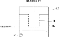
沈殿物ろ過槽110は、図8に示すように、凝集沈殿槽70で生じた沈殿物をろ過する役割を有している。この沈殿物ろ過槽110は、沈殿物ろ過槽本体112と、沈殿物ろ過フィルタ114と、第2水中ポンプ116とを備えている。
As shown in FIG. 8, the
凝集沈殿槽70で生じた沈殿物は、沈殿物ろ過槽本体112内に導かれ、当該沈殿物ろ過槽本体112内に配設された沈殿物ろ過フィルタ114でろ過される。ろ過された後のろ過水は沈殿物ろ過槽本体112の底部に溜まった後、第2水中ポンプ116で汚水貯留槽60に戻される。
The precipitate generated in the
なお、この沈殿物ろ過フィルタ114としては、例えば、土のう袋を使用することができる。
In addition, as this
(汚水処理装置10による処理)
上述の「汚水処理装置10の構成」でも一部を説明したが、本実施例に係る汚水処理装置10によるアスベストを含む汚水の処理について説明する。最初に、真空吸引機20の運転を開始する。すると、真空吸引機20の吸引口22に空気が吸い込まれていき、空気浄化槽30内が負圧になり、遠心分離器本体41内に空気の流れ(旋回流)ができる。さらに、遠心分離器40の吸引口42も負圧になり、吸引具47の先端から空気が吸い込まれるようになって、汚水を吸引する準備が完了する。
(Treatment by the sewage treatment apparatus 10)
Part of the above-described “configuration of the
然る後、解体工事中の建物等に吹き付けられたアスベストを含む塗装面に高圧水を噴射してアスベストを剥離させる。この剥離作業と同時に、剥離させたアスベスト、剥離に用いた水、および、同じく剥離した塗膜片等を含む埃等が混ざった汚水と空気とを吸引具47の先端から吸い込んでいく。
Thereafter, asbestos is peeled off by spraying high-pressure water onto the painted surface containing asbestos sprayed on the building under construction. Simultaneously with the peeling operation, the asbestos peeled off, the water used for the peeling, and the dirty water and the air mixed with the dust including the peeled coating pieces and the like are sucked from the tip of the
吸引具47の先端から吸い込まれた汚水および空気は、吸引口42から遠心分離器本体41内に入り、遠心分離器本体41内の旋回流によって汚水と空気とに分離される。分離された空気は遠心分離器40の排気口44から排出される。また、分離された汚水は汚水排出口46から汚水分離槽50内に導かれる。
The sewage and air sucked from the tip of the
排気口44から排出された空気は空気浄化槽30に入る。空気浄化槽30に入った空気は、空気浄化槽本体31に溜められた浄化用水36によってろ過され、当該空気内に含まれている微量のアスベストや、遠心分離器40で分離しきらず排気口44から空気とともに排出された少量の汚水等が浄化用水36に捕捉される。浄化用水36によってアスベスト等が捕捉されて清浄になった空気は、空気浄化槽30の排気管34から出て真空吸引機本体21に入り、真空吸引機20の排気口24から放出される。
The air discharged from the
一方、遠心分離器40から汚水分離槽50に入った汚水は、汚水分離槽本体51内に配設されたろ過フィルタ56でろ過され、この汚水に含まれる比較的粗いものがろ過フィルタ56で捕捉される。ろ過フィルタ56でろ過された後の汚水は、次に、汚水貯留槽60に導かれる。
On the other hand, the sewage that has entered the
汚水貯留槽60に導かれた汚水は、しばらくの間、汚水貯留槽本体61内で貯留される。これにより、汚水中の水のよりも比重が大きいものが自然沈殿して汚水から分離する。自然沈降した汚泥は適宜除去する。
The sewage guided to the
次に、比重が大きいものが自然沈殿して分離した後の汚水は第1水中ポンプ62で凝集沈殿槽70に送られる。然る後、凝集沈殿槽70に凝集沈殿剤Gが投入され、汚水中の不純物のほとんどが凝集沈殿槽本体71の底部に沈殿する。凝集沈殿槽70への汚水の送水、および、凝集沈殿剤Gの投入は連続して行われ、凝集沈殿処理を受けた上澄み水は凝集沈殿槽本体71に設けられた排水口72から水フィルタ80に送られる。
Next, the sewage that has been separated by natural precipitation of a material having a large specific gravity is sent to the
上澄み水は水フィルタ材82でろ過され、わずかに含まれていたアスベスト等が上澄み水から取り除かれる。水フィルタ材82でろ過されて清浄になった上澄み水はpH調整槽90に導かれる。pH調整槽90で上澄み水のpH調整が実施され、然る後、アスベスト含有量が既定値以下であることを検査した後、pH調整槽本体91に設けられた放流排出口92から上澄み水が放流される。
The supernatant water is filtered by the
最後に、凝集沈殿槽70で生じた沈殿物は、凝集沈殿槽本体71に設けられた沈殿物排出口74から沈殿物ろ過槽110へ送られ、当該沈殿物ろ過槽110内でろ過処理される。
Finally, the precipitate generated in the
(汚水処理装置10の特徴)
(1)
本実施例に係る汚水処理装置10によれば、吸引されたアスベストを含む汚水および吸引に使用した空気からアスベストやその他の廃棄物を取り除き、排気・放流できる程度に空気や水を浄化することができる。
(Characteristics of sewage treatment apparatus 10)
(1)
According to the
(2)
また、本実施例に係る汚水処理装置10によれば、汚水分離槽50におけるろ過フィルタ56として、フレキシブルコンテナバッグを使用している。このように業界での流通量が多く安価であり、かつ、それ自体の運搬や運送を行いやすい形状に成形されているフレキシブルコンテナバッグを使用することにより、ランニングコストの低減を実現させることができるとともに、捕捉された粗いものが詰まったろ過フィルタの取り出しや最終処分場への運搬等を容易に行うことができる。なお、ろ過フィルタ56としてのフレキシブルコンテナバッグで捕捉した粗いものをアスベスト廃棄物運搬袋に移し、特別管理産業廃棄物「廃石綿等」として基準に基づいて処理する。
(2)
Moreover, according to the
(3)
さらに、本実施例に係る汚水処理装置10によれば、水フィルタ材82が3層のカートリッジフィルタ82a,82b,82cで構成されている。これにより、水フィルタ80全体としてのアスベスト捕捉能力が低下してきたときに一部のカートリッジフィルタのみを交換してこのアスベスト捕捉能力を回復させることができる。以上のことから、本実施例に係る汚水処理装置10によれば、ランニングコストの低減を実現させることができる。
(3)
Furthermore, according to the
(4)
また、本実施例に係る汚水処理装置10によれば、水フィルタ材82を構成する3層のカートリッジフィルタ82a,82b,82cは、上流側から下流側に向けて順に目が細かくなるように配置されている。これにより、上澄み水中における粒度の大きい不純物から順に捕捉されるので水フィルタ80のろ過能力を高い状態で安定させることができる。
(4)
Further, according to the
今回開示された実施の形態はすべての点で例示であって制限的なものではないと考えられるべきである。本発明の範囲は、上記した説明ではなく、特許請求の範囲によって示され、特許請求の範囲と均等の意味および範囲内でのすべての変更が含まれることが意図される。 The embodiment disclosed this time should be considered as illustrative in all points and not restrictive. The scope of the present invention is defined by the terms of the claims, rather than the description above, and is intended to include any modifications within the scope and meaning equivalent to the terms of the claims.
10…汚水処理装置
20…真空吸引機、21…真空吸引機本体、22…吸引口、24…排気口
30…空気浄化槽、31…空気浄化槽本体、32…吸引管、34…排気管、36…浄化用水
40…遠心分離器、41…遠心分離器本体、42…吸引口、44…排気口、46…汚水排出口、47…吸引具
50…汚水分離槽、51…汚水分離槽本体、52…汚水受入口、54…排水口、56…ろ過フィルタ
60…汚水貯留槽、61…汚水貯留槽本体、62…第1水中ポンプ
70…凝集沈殿槽、71…凝集沈殿槽本体、72…排水口、74…沈殿物排出口
80…水フィルタ、81…水フィルタ本体、82…水フィルタ材、84…一次口、86…二次口
90…pH調整槽、91…pH調整槽本体、92…放流排出口
100…ろ過水戻し配管
110…沈殿物ろ過槽、112…沈殿物ろ過槽本体、114…沈殿物ろ過フィルタ、116…第2水中ポンプ
DESCRIPTION OF
Claims (3)
前記汚水と前記空気とを互いに分離する遠心分離器と、
前記遠心分離器と前記真空吸引機との間において、前記遠心分離器で分離された前記空気を浄化する空気浄化槽と、
前記遠心分離器で分離された前記汚水をろ過フィルタでろ過する汚水分離槽と、
前記汚水分離槽でろ過された前記汚水を凝集沈殿処理する凝集沈殿槽と、
凝集沈殿処理した上澄み水をろ過する水フィルタ材を有する水フィルタと、
前記水フィルタでろ過した前記上澄み水をpH調整剤で水質調整した後、放流するpH調整槽とを備える汚水処理装置において、
前記ろ過フィルタとして、フレキシブルコンテナバッグが使用されていることを特徴とする汚水処理装置。 A vacuum suction machine for sucking sewage containing asbestos together with air;
A centrifuge for separating the sewage and the air from each other;
An air purification tank for purifying the air separated by the centrifugal separator between the centrifugal separator and the vacuum suction device;
A sewage separation tank for filtering the sewage separated by the centrifuge with a filtration filter;
A coagulation sedimentation tank for coagulating and precipitating the sewage filtered in the sewage separation tank;
A water filter having a water filter material for filtering the coagulated and precipitated supernatant water;
In the sewage treatment apparatus comprising a pH adjustment tank to be discharged after adjusting the water quality of the supernatant water filtered by the water filter with a pH adjuster,
A sewage treatment apparatus, wherein a flexible container bag is used as the filtration filter.
Priority Applications (1)
| Application Number | Priority Date | Filing Date | Title |
|---|---|---|---|
| JP2017135016A JP6863583B2 (en) | 2017-07-10 | 2017-07-10 | Asbestos-containing sewage treatment equipment |
Applications Claiming Priority (1)
| Application Number | Priority Date | Filing Date | Title |
|---|---|---|---|
| JP2017135016A JP6863583B2 (en) | 2017-07-10 | 2017-07-10 | Asbestos-containing sewage treatment equipment |
Publications (2)
| Publication Number | Publication Date |
|---|---|
| JP2019013904A true JP2019013904A (en) | 2019-01-31 |
| JP6863583B2 JP6863583B2 (en) | 2021-04-21 |
Family
ID=65356632
Family Applications (1)
| Application Number | Title | Priority Date | Filing Date |
|---|---|---|---|
| JP2017135016A Active JP6863583B2 (en) | 2017-07-10 | 2017-07-10 | Asbestos-containing sewage treatment equipment |
Country Status (1)
| Country | Link |
|---|---|
| JP (1) | JP6863583B2 (en) |
Cited By (4)
| Publication number | Priority date | Publication date | Assignee | Title |
|---|---|---|---|---|
| JP2019171306A (en) * | 2018-03-29 | 2019-10-10 | 三共通商株式会社 | System for removing asbestos-containing skin part of structure |
| CN112661319A (en) * | 2021-03-17 | 2021-04-16 | 潍坊利金机械设备有限公司 | Sewage pretreatment is with transporting soil pick-up car |
| CN117504513A (en) * | 2024-01-05 | 2024-02-06 | 青岛凯捷重工机械有限公司 | Vacuum tank for lost foam casting production line |
| JP7812165B1 (en) * | 2025-02-07 | 2026-02-09 | 株式会社スペース・コモド | System and method for recovering and processing asbestos-containing finishing coating materials |
Citations (10)
| Publication number | Priority date | Publication date | Assignee | Title |
|---|---|---|---|---|
| US4820315A (en) * | 1987-11-27 | 1989-04-11 | Demarco Thomas M | Vacuum loader and process for removing asbestos and other particulate material |
| JPH01198964A (en) * | 1988-02-03 | 1989-08-10 | Noshiro:Kk | Removal of asbestos-coated film |
| US5589073A (en) * | 1992-04-27 | 1996-12-31 | Gas Research Institute | System and method for removing asbestos and other solid particles from a slurry |
| DE19835135A1 (en) * | 1998-06-30 | 2000-03-16 | Martin Kloeber | Cleaning device for contaminated air comprises use of finely dispersed liquid, high speed rotor and rotated cylindrical filter wall to improve capture of particulates and to centrifugally separate liquid |
| US20090277851A1 (en) * | 2008-05-06 | 2009-11-12 | Dale Pearson | Multiphase Particulate Separation Vacuum |
| JP2010005558A (en) * | 2008-06-27 | 2010-01-14 | Minowa Koki Kk | Water treatment apparatus |
| JP5031495B2 (en) * | 2007-09-07 | 2012-09-19 | 菊水化学工業株式会社 | Wastewater treatment unit at repair or dismantling site |
| JP3192776U (en) * | 2013-12-24 | 2014-09-04 | 志弘 林 | Flexible container bag |
| JP2016056521A (en) * | 2014-09-05 | 2016-04-21 | 株式会社トッププランニングJapan | Processing method for walls containing asbestos |
| JP2016185538A (en) * | 2015-02-19 | 2016-10-27 | 好史 大良 | Method and device for reducing volume |
-
2017
- 2017-07-10 JP JP2017135016A patent/JP6863583B2/en active Active
Patent Citations (10)
| Publication number | Priority date | Publication date | Assignee | Title |
|---|---|---|---|---|
| US4820315A (en) * | 1987-11-27 | 1989-04-11 | Demarco Thomas M | Vacuum loader and process for removing asbestos and other particulate material |
| JPH01198964A (en) * | 1988-02-03 | 1989-08-10 | Noshiro:Kk | Removal of asbestos-coated film |
| US5589073A (en) * | 1992-04-27 | 1996-12-31 | Gas Research Institute | System and method for removing asbestos and other solid particles from a slurry |
| DE19835135A1 (en) * | 1998-06-30 | 2000-03-16 | Martin Kloeber | Cleaning device for contaminated air comprises use of finely dispersed liquid, high speed rotor and rotated cylindrical filter wall to improve capture of particulates and to centrifugally separate liquid |
| JP5031495B2 (en) * | 2007-09-07 | 2012-09-19 | 菊水化学工業株式会社 | Wastewater treatment unit at repair or dismantling site |
| US20090277851A1 (en) * | 2008-05-06 | 2009-11-12 | Dale Pearson | Multiphase Particulate Separation Vacuum |
| JP2010005558A (en) * | 2008-06-27 | 2010-01-14 | Minowa Koki Kk | Water treatment apparatus |
| JP3192776U (en) * | 2013-12-24 | 2014-09-04 | 志弘 林 | Flexible container bag |
| JP2016056521A (en) * | 2014-09-05 | 2016-04-21 | 株式会社トッププランニングJapan | Processing method for walls containing asbestos |
| JP2016185538A (en) * | 2015-02-19 | 2016-10-27 | 好史 大良 | Method and device for reducing volume |
Cited By (5)
| Publication number | Priority date | Publication date | Assignee | Title |
|---|---|---|---|---|
| JP2019171306A (en) * | 2018-03-29 | 2019-10-10 | 三共通商株式会社 | System for removing asbestos-containing skin part of structure |
| CN112661319A (en) * | 2021-03-17 | 2021-04-16 | 潍坊利金机械设备有限公司 | Sewage pretreatment is with transporting soil pick-up car |
| CN117504513A (en) * | 2024-01-05 | 2024-02-06 | 青岛凯捷重工机械有限公司 | Vacuum tank for lost foam casting production line |
| CN117504513B (en) * | 2024-01-05 | 2024-05-03 | 青岛凯捷重工机械有限公司 | Vacuum tank for lost foam casting production line |
| JP7812165B1 (en) * | 2025-02-07 | 2026-02-09 | 株式会社スペース・コモド | System and method for recovering and processing asbestos-containing finishing coating materials |
Also Published As
| Publication number | Publication date |
|---|---|
| JP6863583B2 (en) | 2021-04-21 |
Similar Documents
| Publication | Publication Date | Title |
|---|---|---|
| JP7289000B2 (en) | Flue gas cleaning liquid purification system | |
| JP6863583B2 (en) | Asbestos-containing sewage treatment equipment | |
| CN108033621A (en) | Desulfurization wastewater Zero discharging system and method | |
| JP6689435B2 (en) | Wastewater treatment system and wastewater treatment method | |
| CN101857321A (en) | Method and equipment for treating and recycling reverse osmosis concentrated water and complex wastewater with high salt content | |
| JP6542940B1 (en) | Asbestos-containing surface part removal system for structures | |
| CN203852989U (en) | Integrated waste gas purification equipment of pharmaceutical factory | |
| CN108821500A (en) | A kind of sewage water treatment method of water-jet loom | |
| WO2019150604A1 (en) | Method and apparatus for treating coal wastewater | |
| JP2892948B2 (en) | Separation and removal method of mixture in liquid | |
| JP2004162156A (en) | Cleaning system for metal sheet | |
| JP7812165B1 (en) | System and method for recovering and processing asbestos-containing finishing coating materials | |
| CN110092509A (en) | A kind of intensive style laboratory waste processing system | |
| KR101687380B1 (en) | Regenerative system of filter sand | |
| CN214182337U (en) | Waste gas treatment device for polyamide production | |
| JP7706106B2 (en) | How to treat asbestos-contaminated water | |
| CN215388479U (en) | Tail gas dust collector for excavator engineering machinery | |
| CN212757826U (en) | Boiler tail gas treatment device | |
| JP2008000679A (en) | Waste water treatment apparatus, waste water treatment system, and waste water treatment method | |
| CN117902776A (en) | A system and method for recycling wastewater resources in bulk cargo yard containing coal | |
| CN208071448U (en) | A waste water treatment machine | |
| CN205933426U (en) | Wastewater slag removal device | |
| CN107902806A (en) | A kind of secondary precipitation of Heihe road and biochemical treatment apparatus | |
| CN120663175A (en) | Recovery and purification system and method for machine tool machining cutting fluid | |
| JP2008000680A (en) | Waste water treatment apparatus, waste water treatment system, and waste water treatment method |
Legal Events
| Date | Code | Title | Description |
|---|---|---|---|
| A621 | Written request for application examination |
Free format text: JAPANESE INTERMEDIATE CODE: A621 Effective date: 20200624 |
|
| TRDD | Decision of grant or rejection written | ||
| A01 | Written decision to grant a patent or to grant a registration (utility model) |
Free format text: JAPANESE INTERMEDIATE CODE: A01 Effective date: 20210323 |
|
| A61 | First payment of annual fees (during grant procedure) |
Free format text: JAPANESE INTERMEDIATE CODE: A61 Effective date: 20210325 |
|
| R150 | Certificate of patent or registration of utility model |
Ref document number: 6863583 Country of ref document: JP Free format text: JAPANESE INTERMEDIATE CODE: R150 |
|
| R250 | Receipt of annual fees |
Free format text: JAPANESE INTERMEDIATE CODE: R250 |
|
| R250 | Receipt of annual fees |
Free format text: JAPANESE INTERMEDIATE CODE: R250 |
|
| R250 | Receipt of annual fees |
Free format text: JAPANESE INTERMEDIATE CODE: R250 |