CN112647994A - Anchor rod centering degree experiment device and method based on numerical control drilling machine - Google Patents
Anchor rod centering degree experiment device and method based on numerical control drilling machine Download PDFInfo
- Publication number
- CN112647994A CN112647994A CN202110125739.5A CN202110125739A CN112647994A CN 112647994 A CN112647994 A CN 112647994A CN 202110125739 A CN202110125739 A CN 202110125739A CN 112647994 A CN112647994 A CN 112647994A
- Authority
- CN
- China
- Prior art keywords
- anchor rod
- hole
- similar
- anchor
- centering
- Prior art date
- Legal status (The legal status is an assumption and is not a legal conclusion. Google has not performed a legal analysis and makes no representation as to the accuracy of the status listed.)
- Granted
Links
- 238000005553 drilling Methods 0.000 title claims abstract description 54
- 238000002474 experimental method Methods 0.000 title claims abstract description 32
- 238000000034 method Methods 0.000 title claims abstract description 19
- 238000004873 anchoring Methods 0.000 claims abstract description 92
- 238000012360 testing method Methods 0.000 claims abstract description 9
- 239000011347 resin Substances 0.000 claims description 6
- 229920005989 resin Polymers 0.000 claims description 6
- 238000012545 processing Methods 0.000 claims description 5
- 230000008878 coupling Effects 0.000 claims description 4
- 238000010168 coupling process Methods 0.000 claims description 4
- 238000005859 coupling reaction Methods 0.000 claims description 4
- 238000009434 installation Methods 0.000 claims description 4
- 230000000452 restraining effect Effects 0.000 claims description 3
- 238000003756 stirring Methods 0.000 claims description 3
- 230000007935 neutral effect Effects 0.000 claims description 2
- 238000003556 assay Methods 0.000 claims 1
- 230000008093 supporting effect Effects 0.000 abstract description 15
- 230000000694 effects Effects 0.000 abstract description 8
- 238000011160 research Methods 0.000 abstract description 8
- 238000002360 preparation method Methods 0.000 abstract description 4
- 238000010276 construction Methods 0.000 description 4
- 238000010586 diagram Methods 0.000 description 3
- 230000007547 defect Effects 0.000 description 2
- 238000005516 engineering process Methods 0.000 description 2
- 230000009286 beneficial effect Effects 0.000 description 1
- 239000000463 material Substances 0.000 description 1
Images



Classifications
-
- E—FIXED CONSTRUCTIONS
- E21—EARTH OR ROCK DRILLING; MINING
- E21D—SHAFTS; TUNNELS; GALLERIES; LARGE UNDERGROUND CHAMBERS
- E21D20/00—Setting anchoring-bolts
- E21D20/003—Machines for drilling anchor holes and setting anchor bolts
-
- E—FIXED CONSTRUCTIONS
- E21—EARTH OR ROCK DRILLING; MINING
- E21B—EARTH OR ROCK DRILLING; OBTAINING OIL, GAS, WATER, SOLUBLE OR MELTABLE MATERIALS OR A SLURRY OF MINERALS FROM WELLS
- E21B19/00—Handling rods, casings, tubes or the like outside the borehole, e.g. in the derrick; Apparatus for feeding the rods or cables
- E21B19/24—Guiding or centralising devices for drilling rods or pipes
-
- E—FIXED CONSTRUCTIONS
- E21—EARTH OR ROCK DRILLING; MINING
- E21B—EARTH OR ROCK DRILLING; OBTAINING OIL, GAS, WATER, SOLUBLE OR MELTABLE MATERIALS OR A SLURRY OF MINERALS FROM WELLS
- E21B7/00—Special methods or apparatus for drilling
- E21B7/04—Directional drilling
-
- E—FIXED CONSTRUCTIONS
- E21—EARTH OR ROCK DRILLING; MINING
- E21D—SHAFTS; TUNNELS; GALLERIES; LARGE UNDERGROUND CHAMBERS
- E21D20/00—Setting anchoring-bolts
Landscapes
- Engineering & Computer Science (AREA)
- Mining & Mineral Resources (AREA)
- Life Sciences & Earth Sciences (AREA)
- Geology (AREA)
- General Life Sciences & Earth Sciences (AREA)
- Geochemistry & Mineralogy (AREA)
- Physics & Mathematics (AREA)
- Environmental & Geological Engineering (AREA)
- Fluid Mechanics (AREA)
- Structural Engineering (AREA)
- Mechanical Engineering (AREA)
- Investigating Strength Of Materials By Application Of Mechanical Stress (AREA)
Abstract
The invention relates to an anchor rod centering degree experiment device and method based on a numerical control drilling machine, and the anchor rod centering degree experiment device based on the numerical control drilling machine comprises an anchor rod centering degree adjusting structure, a similar anchoring hole fixing structure and a workbench connecting and fixing structure, wherein the anchor rod centering degree adjusting structure comprises an anchor rod centering degree control component; according to the invention, the control components of the anchor rod centering degrees with different centering degrees are processed by adjusting the position of the anchor rod limiting hole, so that a plurality of anchor rod experiment test pieces with preset centering degrees are accurately screened out, the accurate control of the anchor rod on the centering degrees in the experiment process is realized, and the experiment effect is ensured; the experimental method adopting the device can realize the accurate control of the centering degree of the anchor rod and obtain a series of anchoring test pieces of the centering degree of the anchor rod so as to develop the research on the relation between the centering degree of the anchor rod and the supporting effect of the anchor rod and ensure the preparation and the effectiveness of the experimental effect.
Description
Technical Field
The invention belongs to the technical field of anchor rod support of mines, tunnels, chambers and the like, and particularly relates to an anchor rod centering degree experimental device and method based on a numerical control drilling machine.
Background
The anchor bolt supporting technology is used as an economic and effective supporting method, is widely applied to the underground engineering supporting field of mines, tunnels, chambers and the like in China, and because of the limitation of the construction conditions of the anchor bolt supporting field, the anchor bolt supporting construction becomes a hidden construction process, and the effective research means for the construction quality and effect of the anchor bolt supporting field is lacked, so that the laboratory anchor bolt anchoring experiment can not be separated for analyzing the anchor bolt supporting effect, even analyzing the anchor bolt supporting mechanism; among a plurality of influence factors of the anchor rod supporting quality, relevant researches show that the anchor rod centering degree (the anchor rod centering degree is a quantity representing the deviation degree of the axis position of the anchor rod and the axis position of an anchoring hole, and when the two axis positions are superposed, the anchor rod centering degree is recorded as 1) is one of important factors, so that the research on the relation between the anchor rod centering degree and the anchor rod supporting quality is of great significance; however, when the different centering experiments of the anchor rod are performed under the existing conditions, the situation that the different centering accurate control devices and methods of the anchor rod are lacked is faced, so that in order to further develop the fine research of the anchor rod supporting technology and analyze the relation between the anchor rod supporting quality and the centering degree of the anchor rod, a different centering accurate control device and an experimental method of the anchor rod need to be searched urgently, so that the accurate control of the anchor rod to the centering degree in the experimental process is realized, and the experimental effect is ensured.
Disclosure of Invention
The invention aims to overcome the defects of the prior art, and provides the anchor rod centering experimental device and method based on the numerical control drilling machine, which can effectively overcome the defect of accurate control of the centering degree of the anchor rod in the current experiment and further ensure the preparation of different anchor rods to the research result of the centering laboratory.
The technical scheme adopted by the invention is as follows: the utility model provides an anchor rod centering degree experimental apparatus based on numerical control drilling machine, includes that the anchor rod connects fixed knot to centering degree regulation structure, similar anchor hole fixed knot to construct and workstation and construct, the anchor rod includes the anchor rod centering degree control component, the about block in similar anchor hole bottom, adjust the slider, adjust guide rail, slider fixing bolt to centering degree regulation structure, similar anchor hole fixed knot constructs including similar anchor hole stationary mast, lead screw position control slot hole, similar anchor hole embrace to tighten hoop, the fixed lead screw in similar anchor hole, fastening butterfly nut, stand restraint nut, lead screw coupling nut, embrace to tighten hoop nut, workstation connection fixed knot constructs including PMKD, T type fixed block, numerical control drilling machine workstation, fixing bolt.
The control component of stock centering is the lid form, the control component of stock centering is provided with the spacing hole of stock that is used for the stock inseparable to insert including and is used for the cooperation recess in the similar anchor hole of downward installation.
The about piece setting in similar anchor hole bottom is in the below of the control component of the degree in the stock is middle, be provided with on the about piece in similar anchor hole bottom with the spacing hole in similar anchor hole assorted similar anchor hole, the chucking groove connection that the about piece in similar anchor hole bottom set up through both sides has adjusting block, adjusting block slide and set up on adjusting the guide rail, adjusting the guide rail be provided with the guide rail recess, adjusting block be provided with guide rail recess phase-match with guide rail cooperation groove, the mounted position in similar anchor hole passes through the control of the fixed adjusting block of slider fixing bolt.
Similar anchor hole fixed column is provided with lead screw position control slot hole, similar anchor hole fixed lead screw passes lead screw position control slot hole and can upper and lower adjusting position, similar anchor hole fixed lead screw hold tightly the hoop through lead screw coupling nut and similar anchor hole and connect the both sides in similar anchor hole, similar anchor hole hold tightly the hoop through holding tightly hoop pretightening nut and similar anchor hole fixed connection, the inboard and outboard of lead screw position control slot hole realizes fixing in similar anchor hole through stand restraint nut and fastening butterfly nut respectively.
The anchor rod is in to the adjustment guide rail mechanical connection of neutral adjustment structure on the PMKD of fixed knot structure is connected to the workstation, PMKD passes through T type fixed block and fixing bolt and is connected fixedly with the numerical control drilling machine workstation, the workstation convex groove phase-match on T type fixed block and the numerical control drilling machine workstation, T type fixed block is provided with bolted connection hole, bolted connection hole and fixing bolt cooperation fixed connection.
An experiment method of an anchor rod centering experiment device based on a numerical control drilling machine comprises the following steps:
step 1): processing the upper part of the anchor rod into a numerical control drilling machine clamping section;
step 2): adjusting the position of the anchor rod limiting hole, and processing a plurality of anchor rod centering control members with different centering degrees;
step 3): fixing the T-shaped fixed block on a workbench of the numerical control drilling machine through a fixing bolt;
step 4): installing a similar anchoring hole bottom restraint block on the fixed bottom plate, and inserting the similar anchoring hole into the similar anchoring hole limiting hole;
step 5): sleeving a similar anchoring hole with a clasping hoop on the upper part of the similar anchoring hole, screwing the clasping hoop pre-tightening nut, enabling a lead screw fixed by the similar anchoring hole to penetrate through a lead screw position adjusting long hole and be inserted into a lead screw connecting nut, adjusting the lead screw to a proper position through an upright post restraining nut arranged on the inner side, screwing a fastening butterfly nut on the outer side of the lead screw position adjusting long hole and temporarily performing insufficient pre-tightening;
step 6): inserting the clamping section of the anchor rod into a chuck of the numerical control drilling machine, and fixing firmly;
step 7): sleeving an anchor rod centering control component at the upper end of a similar anchoring hole, starting a numerical control drilling machine, aligning the lower end of an anchor rod, inserting the lower end of the anchor rod into an anchor rod limiting hole for a section of length, simultaneously pre-tightening 2 fastening butterfly nuts, then screwing a slide block fixing bolt, and fixing and adjusting the position of the slide block;
step 8): the anchor rod is pulled out of the anchor rod limiting hole, and then the anchor rod centering control member is taken down from the upper end of the similar anchoring hole;
step 9): filling the resin anchoring agent into the similar anchoring holes, starting the numerical control drilling machine to drive the anchor rod to rotate and move downwards, stirring the resin anchoring agent, and finishing the anchoring of the anchor rod in the similar anchoring holes;
step 10): loosening a chuck of the numerical control drilling machine and a tightening nut of the clasping hoop, and taking down the similar anchoring hole and the anchor rod to complete the anchoring of an anchor rod sample;
step 11): selecting another anchor rod centering control component, and repeating the steps 7) to 10) until the anchoring of all the experimental test pieces is completed.
In the step 2), the position of the anchor rod limiting hole can be adjusted by changing the position relation between the axis position of the control member in the anchor rod centering degree and the axis position of the anchor rod limiting hole.
The invention has the beneficial effects that: the anchor rod centering degree experiment device based on the numerical control drilling machine adopts the anchor rod centering degree control component, and the anchor rod centering degree control components with different centering degrees are processed by adjusting the position of the anchor rod limiting hole, so that a plurality of anchor rod experiment test pieces with preset centering degrees are accurately screened out, the accurate control of the anchor rod to the centering degree in the experiment process is realized, and the experiment effect is ensured; the anchor rod centering adjustment structure and the similar anchoring hole fixing structure can stabilize and adjust the horizontal and vertical positions of the similar anchoring holes, so that the position adjustment can be conveniently carried out when the anchor rod is inserted into the anchor rod limiting hole, and the stability of the whole device in the experimental process can be ensured by adopting the workbench connection fixing structure; by adopting the experiment method of the anchor rod centering experiment device based on the numerical control drilling machine, the accurate control of the anchor rod centering degree can be realized, and a series of anchor test pieces of the anchor rod centering degree can be obtained, so that the research on the relation between the anchor rod centering degree and the anchor rod supporting effect can be conveniently carried out, and the preparation and the effectiveness of the experiment effect can be ensured.
Drawings
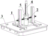
FIG. 1 is a schematic overall structure diagram of an anchor rod centering experimental device based on a numerical control drilling machine;
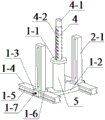
FIG. 2 is a schematic structural view of a centering adjustment structure of the anchor rod of the present invention;
FIG. 3 is a schematic structural view of the bolt centering control member of the present invention;
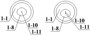
fig. 4 is an elevation view of a bolt centering control member of various centering degrees in accordance with the present invention;
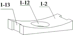
FIG. 5 is a schematic structural view of a similar anchoring hole bottom restraint block of the present invention;
FIG. 6 is a schematic structural view of a similar anchoring hole fixing structure of the present invention;
FIG. 7 is a schematic structural view of a connecting and fixing structure of a workbench according to the present invention;
FIG. 8 is a schematic structural diagram of a workbench of a numerically controlled drilling machine according to the present invention;
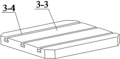
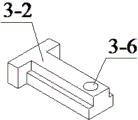
FIG. 9 is a schematic structural diagram of a T-shaped fixing block according to the present invention;
in the figure: 1. 1-1 anchor rod centering degree adjusting structure, 1-2 anchor rod centering degree control component, 1-3 similar anchoring hole bottom restricting block, 1-4 adjusting slider, 1-5 adjusting guide rail, 1-6 guide rail groove, 1-7 guide rail matching groove, 1-8 slider fixing bolt, 1-9 anchor rod limiting hole, 1-10 matching groove, 1-11 anchor rod centering degree control component axis position, 1-12 anchor rod limiting hole axis position, 1-13 similar anchoring hole limiting hole, 2 clamping groove, 2-1 similar anchoring hole fixing structure, 2-2 similar anchoring hole fixing upright post, 2-3 screw rod position adjusting long hole, 2-4 similar anchoring hole clamping hoop, 2-5 similar anchoring hole fixing screw rod, The device comprises the following components, by weight, 2-6 parts of fastening butterfly nuts, 2-7 parts of column restraint nuts, 2-8 parts of lead screw connecting nuts, 3-3 parts of hoop pre-tightening nuts, 3-1 parts of a workbench connecting and fixing structure, 3-2 parts of a fixing base plate, 3-3 parts of T-shaped fixing blocks, 3-4 parts of a numerical control drilling machine workbench, 3-5 parts of a workbench convex groove, 3-6 parts of fixing bolts, 4 parts of bolt connecting holes, 4-1 parts of anchor rods, 5 parts of clamping sections of the numerical control drilling machine and similar anchoring holes.
Detailed Description
The technical solution in the embodiments of the present invention will be clearly and completely described below with reference to the accompanying drawings in the embodiments of the present invention. All other embodiments, which can be obtained by a person skilled in the art without making any creative effort based on the embodiments of the present invention, belong to the protection scope of the present invention, and are specifically described below with reference to the embodiments.
As shown in FIGS. 1-9, an stock centering experimental apparatus based on numerical control drilling machine, including stock centering adjustment structure 1, similar anchorage hole fixed knot construct 2 and workstation connection fixed knot construct 3, its characterized in that: the anchor rod centering degree adjusting structure 1 comprises an anchor rod centering degree control component 1-1, a similar anchoring hole bottom restraint block 1-2, an adjusting slider 1-3, an adjusting guide rail 1-4 and a slider fixing bolt 1-7, the similar anchoring hole fixing structure 2 comprises a similar anchoring hole fixing upright post 2-1, a screw rod position adjusting long hole 2-2, a similar anchoring hole holding hoop 2-3, a similar anchoring hole fixing screw rod 2-4, a fastening butterfly nut 2-5, an upright post restraint nut 2-6, a screw rod connecting nut 2-7 and a holding hoop pre-tightening nut 2-8, and the workbench connecting and fixing structure 3 comprises a fixing bottom plate 3-1, a T-shaped fixing block 3=2, a numerical control drilling machine workbench 3-2 and a fixing bolt 3-5.
The anchor rod centering degree control member 1-1 is the lid form, the anchor rod centering degree control member 1-1 is provided with the anchor rod spacing hole 1-8 that is used for anchor rod 4 closely to insert including and is used for the cooperation recess 1-9 of similar anchor hole 5 of installation downwards, the position of anchor rod spacing hole 1-8 is fixed, and the control of the different centering degree of anchor rod 4 can be realized through changing anchor rod centering degree control member 1-1 that the anchor rod spacing hole 1-8 position is different.
The similar anchoring hole bottom restraint block 1-2 is arranged below the anchor rod centering control member 1-1, the similar anchoring hole bottom restraint block 1-2 is provided with a similar anchoring hole limiting hole 1-12 matched with the similar anchoring hole 5, the similar anchoring hole bottom restraint block 1-2 is connected with an adjusting slide block 1-3 through clamping grooves 1-13 arranged on two sides, the adjusting slide block 1-3 is arranged on the adjusting guide rail 1-4 in a sliding way, the adjusting guide rail 1-4 is provided with a guide rail groove 1-5, the adjusting slide block 1-3 is provided with a guide rail matching groove 1-6 matched with the guide rail groove 1-5, and the installation position of the similar anchoring hole 5 is controlled by fixing the adjusting slide block 1-3 through a slide block fixing bolt 1-7.
The similar anchoring hole fixing upright 2-1 is provided with a screw rod position adjusting long hole 2-2, the similar anchoring hole fixing screw rod 2-4 penetrates through the screw rod position adjusting long hole 2-2 to be capable of adjusting the position up and down, the similar anchoring hole fixing screw rod 2-4 is connected with the similar anchoring hole hooping hoop 2-3 on two sides of the similar anchoring hole 5 through a screw rod connecting nut 2-7, the similar anchoring hole hooping hoop 2-3 is fixedly connected with the similar anchoring hole 5 through a hooping hoop pre-tightening nut 2-8, and the inner side and the outer side of the screw rod position adjusting long hole 2-2 are respectively fixed with the fastening butterfly nut 2-5 through an upright post restraining nut 2-6.
The anchor rod is mechanically connected to an adjusting guide rail 1-4 of the centering adjusting structure 1 on a fixing bottom plate 3-1 of the workbench connecting and fixing structure 3, the fixing bottom plate 3-1 is fixedly connected with a numerical control drilling machine workbench 3-3 through a T-shaped fixing block 3-2 and a fixing bolt 3-5, the T-shaped fixing block 3-2 is matched with a workbench convex groove 3-4 on the numerical control drilling machine workbench 3-3, the T-shaped fixing block 3-2 is provided with a bolt connecting hole 3-6, and the bolt connecting hole 3-6 is fixedly connected with the fixing bolt 3-5 in a matched mode.
An experiment method of an anchor rod centering experiment device based on a numerical control drilling machine comprises the following steps:
step 1): the upper part of the anchor rod 4 is processed into a cylindrical numerical control drilling machine clamping section 4-1, so that the numerical control drilling machine can conveniently clamp the anchor rod 4, and the axis of the anchor rod can be effectively ensured to be coincident with the rotation axis of the anchor rod;
step 2): preparing a certain number of anchor rod centering degree control members 1-1, adjusting the positions of anchor rod limiting holes 1-8 according to experiment requirements, processing the anchor rod centering degree control members 1-1 into different centering degrees, and adjusting the positions of the anchor rod limiting holes 1-8 by changing the position relation between the axial line positions 1-10 of the anchor rod centering degree control members and the axial line positions 1-11 of the anchor rod limiting holes;
step 3): when all experimental materials are completely prepared, inserting the T-shaped fixed block 3-2 into a proper position of the convex groove 3-4 of the workbench, integrally fixing the device on the workbench 3-3 of the numerical control drilling machine through a fixed bolt 3-5, and screwing the fixed bolt 3-5 to prevent the device from moving;
step 4): after the device is fixed, the similar anchoring hole bottom restraint blocks 1-2 are installed at corresponding positions of the fixed bottom plate 3-1, and the similar anchoring hole 5 is inserted into the similar anchoring hole limiting holes 1-12;
step 5): sleeving the similar anchoring hole clasping hoop 2-3 at a position, away from the upper end, of the similar anchoring hole 5, and screwing the clasping hoop pre-tightening nut 2-8 tightly, so that the similar anchoring hole clasping hoop 2-3 is fixed outside the similar anchoring hole 5; the similar anchoring hole fixing screw rod 2-4 penetrates through the screw rod position adjusting long hole 2-2, the column restraint nut 2-6 is installed on the inner side of the similar anchoring hole fixing screw rod 2-4 and adjusted to a proper position, the similar anchoring hole fixing screw rod 2-4 is inserted into the screw rod connecting nut 2-7 on the similar anchoring hole hooping hoop 2-3, the similar anchoring hole fixing screw rod 2-4 is screwed, the butterfly nut 2-5 is screwed on the outer side of the similar anchoring hole fixing screw rod 2-4, and the butterfly nut 2-5 is temporarily and insufficiently pre-tightened.
Step 6): inserting the numerical control drilling machine clamping section 4-1 at the upper part of the anchor rod 4 into a chuck of the numerical control drilling machine, and screwing the chuck of the numerical control drilling machine to firmly fix the anchor rod 4;
step 7): sleeving an anchor rod centering control member 1-1 at the upper end of a similar anchoring hole 5, adjusting the height of an anchor rod 4 through an adjusting button on a numerical control drilling machine, aligning the lower end of the anchor rod 4 to an anchor rod limiting hole 1-8 on the anchor rod centering control member 1-1, if the positions of the anchor rod 4 and the anchor rod limiting hole 1-8 are deviated, by adjusting the positions of the adjusting sliding blocks 1 to 3 on the adjusting guide rails 1 to 4 until the anchor rod 4 is inserted into the anchor rod limiting holes 1 to 8, the anchor rod 4 is inserted into the anchor rod limiting holes 1 to 8 for a section of length, simultaneously pre-tightening 2 fastening butterfly screws 2-5, pressing the fastening butterfly nuts 2-5 onto the similar anchoring holes to fix the upright post 2-1, realizing the fixation of the similar anchoring holes 5, then, screwing down the sliding block fixing bolts 1-7, and fixing and adjusting the positions of the sliding blocks 1-3;
step 8): adjusting a corresponding adjusting button on the numerical control drilling machine, pulling out the anchor rod 4 from the anchor rod limiting hole 1-8 for a certain distance, and then taking down the anchor rod centering control member 1-1 from the upper end of the similar anchoring hole 5;
step 9): filling the resin anchoring agent into the similar anchoring holes 5, starting the numerical control drilling machine to drive the anchor rods 4 to rotate and move downwards, stirring the resin anchoring agent, and finishing the anchoring of the anchor rods 4 in the similar anchoring holes 5;
step 10): loosening the chuck of the numerical control drilling machine and the tightening nut 2-8 of the clasping hoop, and taking down the similar anchoring hole 5 and the anchor rod 4 to finish the anchoring of an anchor rod sample;
step 11): selecting another anchor rod centering control member 1-1, and repeating the steps 7) to 10) until the anchoring of all experimental test pieces is completed.
The anchor rod centering degree experiment device based on the numerical control drilling machine adopts the anchor rod centering degree control component, and the anchor rod centering degree control components 1-1 with different centering degrees are processed by adjusting the positions of the anchor rod limiting holes 1-8, so that a plurality of anchor rod experiment test pieces with preset centering degrees are accurately screened out, the accurate control of the anchor rod centering degree in the experiment process is realized, and the experiment effect is ensured; the anchor rod centering adjustment structure 1 and the similar anchoring hole fixing structure 2 can stabilize and adjust the horizontal and vertical positions of the similar anchoring holes 5, can facilitate position adjustment when the anchor rod 4 is inserted into the anchor rod limiting holes 1-8, and can ensure the stability of the whole device in the experimental process by adopting the workbench to be connected with the fixing structure 3; by adopting the experiment method of the anchor rod centering experiment device based on the numerical control drilling machine, the accurate control of the anchor rod centering degree can be realized, and a series of anchor test pieces of the anchor rod centering degree can be obtained, so that the research on the relation between the anchor rod centering degree and the anchor rod supporting effect can be conveniently carried out, and the preparation and the effectiveness of the experiment effect can be ensured.
It will be evident to those skilled in the art that the invention is not limited to the details of the foregoing illustrative embodiments, and that the present invention may be embodied in other specific forms without departing from the spirit or essential attributes thereof. The present embodiments are therefore to be considered in all respects as illustrative and not restrictive, the scope of the invention being indicated by the appended claims rather than by the foregoing description, and all changes which come within the meaning and range of equivalency of the claims are therefore intended to be embraced therein. Any reference sign in a claim should not be construed as limiting the claim concerned.
Claims (7)
1. The utility model provides an anchor rod centering experimental apparatus based on numerical control drilling machine, includes that the anchor rod adjusts structure, similar anchor hole fixed knot construct and workstation connection fixed knot construct to the centering, its characterized in that: the anchor rod is to the degree regulation structure including the anchor rod centering degree control member, the about piece in similar anchor hole bottom, adjust the slider, adjust guide rail, slider fixing bolt, similar anchor hole fixed knot constructs including similar anchor hole stationary mast, lead screw position control slot hole, similar anchor hole embrace tightly hoop, the fixed lead screw of similar anchor hole, fastening butterfly nut, stand restraint nut, lead screw coupling nut, embrace tightly hoop pretightening nut, the fixed knot structure is connected to the workstation includes PMKD, T type fixed block, numerical control drilling machine workstation, fixing bolt.
2. The anchor rod centering experimental device based on the numerical control drilling machine is characterized in that: the control component of stock centering is the lid form, the control component of stock centering is provided with the spacing hole of stock that is used for the stock inseparable to insert including and is used for the cooperation recess in the similar anchor hole of downward installation.
3. The anchor rod centering experimental device based on the numerical control drilling machine is characterized in that: the about piece setting in similar anchor hole bottom is in the below of the control component of the degree in the stock is middle, be provided with on the about piece in similar anchor hole bottom with the spacing hole in similar anchor hole assorted similar anchor hole, the chucking groove connection that the about piece in similar anchor hole bottom set up through both sides has adjusting block, adjusting block slide and set up on adjusting the guide rail, adjusting the guide rail be provided with the guide rail recess, adjusting block be provided with guide rail recess phase-match with guide rail cooperation groove, the mounted position in similar anchor hole passes through the control of the fixed adjusting block of slider fixing bolt.
4. The anchor rod centering experimental device based on the numerical control drilling machine is characterized in that: similar anchor hole fixed column is provided with lead screw position control slot hole, similar anchor hole fixed lead screw passes lead screw position control slot hole and can upper and lower adjusting position, similar anchor hole fixed lead screw hold tightly the hoop through lead screw coupling nut and similar anchor hole and connect the both sides in similar anchor hole, similar anchor hole hold tightly the hoop through holding tightly hoop pretightening nut and similar anchor hole fixed connection, the inboard and outboard of lead screw position control slot hole realizes fixing in similar anchor hole through stand restraint nut and fastening butterfly nut respectively.
5. The anchor rod centering experimental device based on the numerical control drilling machine is characterized in that: the anchor rod is in to the adjustment guide rail mechanical connection of neutral adjustment structure on the PMKD of fixed knot structure is connected to the workstation, PMKD passes through T type fixed block and fixing bolt and is connected fixedly with the numerical control drilling machine workstation, the workstation convex groove phase-match on T type fixed block and the numerical control drilling machine workstation, T type fixed block is provided with bolted connection hole, bolted connection hole and fixing bolt cooperation fixed connection.
6. An experimental method using the apparatus of claim 1, characterized in that: the method comprises the following steps:
step 1): processing the upper part of the anchor rod into a numerical control drilling machine clamping section;
step 2): adjusting the position of the anchor rod limiting hole, and processing a plurality of anchor rod centering control members with different centering degrees;
step 3): fixing the T-shaped fixed block on a workbench of the numerical control drilling machine through a fixing bolt;
step 4): installing a similar anchoring hole bottom restraint block on the fixed bottom plate, and inserting the similar anchoring hole into the similar anchoring hole limiting hole;
step 5): sleeving a similar anchoring hole with a clasping hoop on the upper part of the similar anchoring hole, screwing the clasping hoop pre-tightening nut, enabling a lead screw fixed by the similar anchoring hole to penetrate through a lead screw position adjusting long hole and be inserted into a lead screw connecting nut, adjusting the lead screw to a proper position through an upright post restraining nut arranged on the inner side, screwing a fastening butterfly nut on the outer side of the lead screw position adjusting long hole and temporarily performing insufficient pre-tightening;
step 6): inserting the clamping section of the anchor rod into a chuck of the numerical control drilling machine, and fixing firmly;
step 7): sleeving an anchor rod centering control component at the upper end of a similar anchoring hole, starting a numerical control drilling machine, aligning the lower end of an anchor rod, inserting the lower end of the anchor rod into an anchor rod limiting hole for a section of length, simultaneously pre-tightening 2 fastening butterfly nuts, then screwing a slide block fixing bolt, and fixing and adjusting the position of the slide block;
step 8): the anchor rod is pulled out of the anchor rod limiting hole, and then the anchor rod centering control member is taken down from the upper end of the similar anchoring hole;
step 9): filling the resin anchoring agent into the similar anchoring holes, starting the numerical control drilling machine to drive the anchor rod to rotate and move downwards, stirring the resin anchoring agent, and finishing the anchoring of the anchor rod in the similar anchoring holes;
step 10): loosening a chuck of the numerical control drilling machine and a tightening nut of the clasping hoop, and taking down the similar anchoring hole and the anchor rod to complete the anchoring of an anchor rod sample;
step 11): selecting another anchor rod centering control component, and repeating the steps 7) to 10) until the anchoring of all the experimental test pieces is completed.
7. An assay method according to claim 6, wherein: in the step 2), the position of the anchor rod limiting hole can be adjusted by changing the position relation between the axis position of the control member in the anchor rod centering degree and the axis position of the anchor rod limiting hole.
Priority Applications (1)
| Application Number | Priority Date | Filing Date | Title |
|---|---|---|---|
| CN202110125739.5A CN112647994B (en) | 2021-01-29 | 2021-01-29 | Anchor rod centering degree experiment device and method based on numerical control drilling machine |
Applications Claiming Priority (1)
| Application Number | Priority Date | Filing Date | Title |
|---|---|---|---|
| CN202110125739.5A CN112647994B (en) | 2021-01-29 | 2021-01-29 | Anchor rod centering degree experiment device and method based on numerical control drilling machine |
Publications (2)
| Publication Number | Publication Date |
|---|---|
| CN112647994A true CN112647994A (en) | 2021-04-13 |
| CN112647994B CN112647994B (en) | 2023-02-24 |
Family
ID=75370842
Family Applications (1)
| Application Number | Title | Priority Date | Filing Date |
|---|---|---|---|
| CN202110125739.5A Active CN112647994B (en) | 2021-01-29 | 2021-01-29 | Anchor rod centering degree experiment device and method based on numerical control drilling machine |
Country Status (1)
| Country | Link |
|---|---|
| CN (1) | CN112647994B (en) |
Citations (12)
| Publication number | Priority date | Publication date | Assignee | Title |
|---|---|---|---|---|
| GB956449A (en) * | 1959-07-27 | 1964-04-29 | Becker Prunte G M B H | Improvements in anchor supports for roofs and walls of underground workings |
| JP2008019581A (en) * | 2006-07-11 | 2008-01-31 | Furukawa Rock Drill Co Ltd | Drilling unit for rock bolt, and method for drilling hole for rock bolt |
| CN201318181Y (en) * | 2008-11-28 | 2009-09-30 | 天地科技股份有限公司 | Anchor rope or anchor rod equipped with centering bracket |
| CN201792012U (en) * | 2010-09-13 | 2011-04-13 | 山东唐口煤业有限公司 | Anchor rod tray drilling automatic aligning mold |
| KR101254457B1 (en) * | 2012-03-20 | 2013-04-12 | 김종훈 | Anchor bolt alignment module and vertical-beam support structure with the same |
| CN204964087U (en) * | 2015-07-31 | 2016-01-13 | 河南理工大学 | Stock anchor power testing experiment device |
| JP6200115B1 (en) * | 2017-05-11 | 2017-09-20 | 前田工繊株式会社 | Drilling guide device and guide hole drilling method |
| CN206832585U (en) * | 2017-06-19 | 2018-01-02 | 河北建筑工程学院 | Use for laboratory anchor system test device |
| CN207764102U (en) * | 2018-01-11 | 2018-08-24 | 山东科技大学 | Halfbody anchor structure stress and deformation field synchronous test system |
| CN109443736A (en) * | 2018-12-21 | 2019-03-08 | 河南理工大学 | Easy mobile multifunctional is crept into automatically and emulates anchor rod anchored testing stand for a kind of laboratory |
| CN208982081U (en) * | 2018-11-01 | 2019-06-14 | 河南理工大学 | The quick detachable anchor rod anchored stirring attachment device of automatic centering |
| US20210003490A1 (en) * | 2019-07-05 | 2021-01-07 | Shandong University Of Science And Technology | Device and method for anchor bolt (cable) supporting structure test and anchoring system performance comprehensive experiment |
-
2021
- 2021-01-29 CN CN202110125739.5A patent/CN112647994B/en active Active
Patent Citations (12)
| Publication number | Priority date | Publication date | Assignee | Title |
|---|---|---|---|---|
| GB956449A (en) * | 1959-07-27 | 1964-04-29 | Becker Prunte G M B H | Improvements in anchor supports for roofs and walls of underground workings |
| JP2008019581A (en) * | 2006-07-11 | 2008-01-31 | Furukawa Rock Drill Co Ltd | Drilling unit for rock bolt, and method for drilling hole for rock bolt |
| CN201318181Y (en) * | 2008-11-28 | 2009-09-30 | 天地科技股份有限公司 | Anchor rope or anchor rod equipped with centering bracket |
| CN201792012U (en) * | 2010-09-13 | 2011-04-13 | 山东唐口煤业有限公司 | Anchor rod tray drilling automatic aligning mold |
| KR101254457B1 (en) * | 2012-03-20 | 2013-04-12 | 김종훈 | Anchor bolt alignment module and vertical-beam support structure with the same |
| CN204964087U (en) * | 2015-07-31 | 2016-01-13 | 河南理工大学 | Stock anchor power testing experiment device |
| JP6200115B1 (en) * | 2017-05-11 | 2017-09-20 | 前田工繊株式会社 | Drilling guide device and guide hole drilling method |
| CN206832585U (en) * | 2017-06-19 | 2018-01-02 | 河北建筑工程学院 | Use for laboratory anchor system test device |
| CN207764102U (en) * | 2018-01-11 | 2018-08-24 | 山东科技大学 | Halfbody anchor structure stress and deformation field synchronous test system |
| CN208982081U (en) * | 2018-11-01 | 2019-06-14 | 河南理工大学 | The quick detachable anchor rod anchored stirring attachment device of automatic centering |
| CN109443736A (en) * | 2018-12-21 | 2019-03-08 | 河南理工大学 | Easy mobile multifunctional is crept into automatically and emulates anchor rod anchored testing stand for a kind of laboratory |
| US20210003490A1 (en) * | 2019-07-05 | 2021-01-07 | Shandong University Of Science And Technology | Device and method for anchor bolt (cable) supporting structure test and anchoring system performance comprehensive experiment |
Non-Patent Citations (1)
| Title |
|---|
| 康红普等: "树脂锚杆锚固性能及影响因素分析", 《煤炭学报》 * |
Also Published As
| Publication number | Publication date |
|---|---|
| CN112647994B (en) | 2023-02-24 |
Similar Documents
| Publication | Publication Date | Title |
|---|---|---|
| CN206710084U (en) | Bushing test fixture | |
| CN113188903B (en) | Welding point connection strength test system | |
| CN112647994B (en) | Anchor rod centering degree experiment device and method based on numerical control drilling machine | |
| CN210465163U (en) | Multifunctional mechanical test tool for embedded channel | |
| CN210051526U (en) | Anti-dazzle board anti-wind load testing machine | |
| CN211904893U (en) | Clamping device applied to shear test of creep testing machine | |
| CN218481321U (en) | Clamping device of large-tonnage hydraulic tension testing machine | |
| CN210922532U (en) | Anti-deformation detection device for anti-dazzle plate | |
| CN210533877U (en) | Concrete test block pressure testing machine based on video monitoring | |
| CN209743486U (en) | through stay cable anchor bolt | |
| CN108645790B (en) | Loading device for axial extraction force test of screw | |
| CN109724784B (en) | Method for testing tensile resistance of threads of photovoltaic panel mounting structure | |
| CN112629959A (en) | Pneumatic stirring sampling device for sampler | |
| CN218984491U (en) | Positioning fixture for part machining | |
| CN219967689U (en) | Clamp for machining multiple specifications | |
| CN220819627U (en) | Reinforced concrete test device with wide application range | |
| CN205225084U (en) | Take stop device's drilling to get core machine | |
| CN221484989U (en) | Horizontal tensile testing device of plush toy | |
| CN221280842U (en) | Trapezoidal screw rod torsion detection equipment | |
| CN109724736A (en) | Experimental rig for the detection of lockset closing force | |
| CN204964300U (en) | Elongation test device when steel cable and steel cable cover atress | |
| CN220063628U (en) | Rectangular section size-adjustable quasi-static test column support device | |
| CN218067420U (en) | Inspection device | |
| CN219581594U (en) | Frock clamp for riveting | |
| CN219512009U (en) | Laboratory is with concrete early strength blade shearing test device |
Legal Events
| Date | Code | Title | Description |
|---|---|---|---|
| PB01 | Publication | ||
| PB01 | Publication | ||
| SE01 | Entry into force of request for substantive examination | ||
| SE01 | Entry into force of request for substantive examination | ||
| GR01 | Patent grant | ||
| GR01 | Patent grant |