CN112636675A - Windproof photovoltaic solar panel - Google Patents
Windproof photovoltaic solar panel Download PDFInfo
- Publication number
- CN112636675A CN112636675A CN202011615297.4A CN202011615297A CN112636675A CN 112636675 A CN112636675 A CN 112636675A CN 202011615297 A CN202011615297 A CN 202011615297A CN 112636675 A CN112636675 A CN 112636675A
- Authority
- CN
- China
- Prior art keywords
- cavity
- block
- centrifugal
- fixedly connected
- blade
- Prior art date
- Legal status (The legal status is an assumption and is not a legal conclusion. Google has not performed a legal analysis and makes no representation as to the accuracy of the status listed.)
- Granted
Links
- 238000004140 cleaning Methods 0.000 claims description 7
- 230000002146 bilateral effect Effects 0.000 claims description 6
- 230000001174 ascending effect Effects 0.000 claims description 4
- 238000005119 centrifugation Methods 0.000 claims 2
- 241000196324 Embryophyta Species 0.000 abstract description 8
- 230000031700 light absorption Effects 0.000 abstract description 4
- 241000124284 Mitella diphylla Species 0.000 abstract 1
- 230000009286 beneficial effect Effects 0.000 description 3
- 230000000149 penetrating effect Effects 0.000 description 2
- 230000000694 effects Effects 0.000 description 1
- 239000000463 material Substances 0.000 description 1
- 238000000034 method Methods 0.000 description 1
- 238000012986 modification Methods 0.000 description 1
- 230000004048 modification Effects 0.000 description 1
- 230000002093 peripheral effect Effects 0.000 description 1
- 239000004065 semiconductor Substances 0.000 description 1
Images


Classifications
-
- H—ELECTRICITY
- H02—GENERATION; CONVERSION OR DISTRIBUTION OF ELECTRIC POWER
- H02S—GENERATION OF ELECTRIC POWER BY CONVERSION OF INFRARED RADIATION, VISIBLE LIGHT OR ULTRAVIOLET LIGHT, e.g. USING PHOTOVOLTAIC [PV] MODULES
- H02S20/00—Supporting structures for PV modules
- H02S20/30—Supporting structures being movable or adjustable, e.g. for angle adjustment
-
- A—HUMAN NECESSITIES
- A01—AGRICULTURE; FORESTRY; ANIMAL HUSBANDRY; HUNTING; TRAPPING; FISHING
- A01D—HARVESTING; MOWING
- A01D34/00—Mowers; Mowing apparatus of harvesters
- A01D34/01—Mowers; Mowing apparatus of harvesters characterised by features relating to the type of cutting apparatus
- A01D34/412—Mowers; Mowing apparatus of harvesters characterised by features relating to the type of cutting apparatus having rotating cutters
- A01D34/42—Mowers; Mowing apparatus of harvesters characterised by features relating to the type of cutting apparatus having rotating cutters having cutters rotating about a horizontal axis, e.g. cutting-cylinders
- A01D34/52—Cutting apparatus
-
- A—HUMAN NECESSITIES
- A01—AGRICULTURE; FORESTRY; ANIMAL HUSBANDRY; HUNTING; TRAPPING; FISHING
- A01D—HARVESTING; MOWING
- A01D34/00—Mowers; Mowing apparatus of harvesters
- A01D34/01—Mowers; Mowing apparatus of harvesters characterised by features relating to the type of cutting apparatus
- A01D34/412—Mowers; Mowing apparatus of harvesters characterised by features relating to the type of cutting apparatus having rotating cutters
- A01D34/42—Mowers; Mowing apparatus of harvesters characterised by features relating to the type of cutting apparatus having rotating cutters having cutters rotating about a horizontal axis, e.g. cutting-cylinders
- A01D34/56—Driving mechanisms for the cutters
-
- A—HUMAN NECESSITIES
- A01—AGRICULTURE; FORESTRY; ANIMAL HUSBANDRY; HUNTING; TRAPPING; FISHING
- A01D—HARVESTING; MOWING
- A01D34/00—Mowers; Mowing apparatus of harvesters
- A01D34/01—Mowers; Mowing apparatus of harvesters characterised by features relating to the type of cutting apparatus
- A01D34/412—Mowers; Mowing apparatus of harvesters characterised by features relating to the type of cutting apparatus having rotating cutters
- A01D34/42—Mowers; Mowing apparatus of harvesters characterised by features relating to the type of cutting apparatus having rotating cutters having cutters rotating about a horizontal axis, e.g. cutting-cylinders
- A01D34/62—Other details
-
- A—HUMAN NECESSITIES
- A01—AGRICULTURE; FORESTRY; ANIMAL HUSBANDRY; HUNTING; TRAPPING; FISHING
- A01M—CATCHING, TRAPPING OR SCARING OF ANIMALS; APPARATUS FOR THE DESTRUCTION OF NOXIOUS ANIMALS OR NOXIOUS PLANTS
- A01M21/00—Apparatus for the destruction of unwanted vegetation, e.g. weeds
- A01M21/02—Apparatus for mechanical destruction
-
- F—MECHANICAL ENGINEERING; LIGHTING; HEATING; WEAPONS; BLASTING
- F24—HEATING; RANGES; VENTILATING
- F24S—SOLAR HEAT COLLECTORS; SOLAR HEAT SYSTEMS
- F24S30/00—Arrangements for moving or orienting solar heat collector modules
- F24S30/40—Arrangements for moving or orienting solar heat collector modules for rotary movement
- F24S30/42—Arrangements for moving or orienting solar heat collector modules for rotary movement with only one rotation axis
- F24S30/425—Horizontal axis
-
- H—ELECTRICITY
- H02—GENERATION; CONVERSION OR DISTRIBUTION OF ELECTRIC POWER
- H02S—GENERATION OF ELECTRIC POWER BY CONVERSION OF INFRARED RADIATION, VISIBLE LIGHT OR ULTRAVIOLET LIGHT, e.g. USING PHOTOVOLTAIC [PV] MODULES
- H02S40/00—Components or accessories in combination with PV modules, not provided for in groups H02S10/00 - H02S30/00
-
- Y—GENERAL TAGGING OF NEW TECHNOLOGICAL DEVELOPMENTS; GENERAL TAGGING OF CROSS-SECTIONAL TECHNOLOGIES SPANNING OVER SEVERAL SECTIONS OF THE IPC; TECHNICAL SUBJECTS COVERED BY FORMER USPC CROSS-REFERENCE ART COLLECTIONS [XRACs] AND DIGESTS
- Y02—TECHNOLOGIES OR APPLICATIONS FOR MITIGATION OR ADAPTATION AGAINST CLIMATE CHANGE
- Y02E—REDUCTION OF GREENHOUSE GAS [GHG] EMISSIONS, RELATED TO ENERGY GENERATION, TRANSMISSION OR DISTRIBUTION
- Y02E10/00—Energy generation through renewable energy sources
- Y02E10/40—Solar thermal energy, e.g. solar towers
- Y02E10/47—Mountings or tracking
-
- Y—GENERAL TAGGING OF NEW TECHNOLOGICAL DEVELOPMENTS; GENERAL TAGGING OF CROSS-SECTIONAL TECHNOLOGIES SPANNING OVER SEVERAL SECTIONS OF THE IPC; TECHNICAL SUBJECTS COVERED BY FORMER USPC CROSS-REFERENCE ART COLLECTIONS [XRACs] AND DIGESTS
- Y02—TECHNOLOGIES OR APPLICATIONS FOR MITIGATION OR ADAPTATION AGAINST CLIMATE CHANGE
- Y02E—REDUCTION OF GREENHOUSE GAS [GHG] EMISSIONS, RELATED TO ENERGY GENERATION, TRANSMISSION OR DISTRIBUTION
- Y02E10/00—Energy generation through renewable energy sources
- Y02E10/50—Photovoltaic [PV] energy
-
- Y—GENERAL TAGGING OF NEW TECHNOLOGICAL DEVELOPMENTS; GENERAL TAGGING OF CROSS-SECTIONAL TECHNOLOGIES SPANNING OVER SEVERAL SECTIONS OF THE IPC; TECHNICAL SUBJECTS COVERED BY FORMER USPC CROSS-REFERENCE ART COLLECTIONS [XRACs] AND DIGESTS
- Y02—TECHNOLOGIES OR APPLICATIONS FOR MITIGATION OR ADAPTATION AGAINST CLIMATE CHANGE
- Y02P—CLIMATE CHANGE MITIGATION TECHNOLOGIES IN THE PRODUCTION OR PROCESSING OF GOODS
- Y02P60/00—Technologies relating to agriculture, livestock or agroalimentary industries
- Y02P60/12—Technologies relating to agriculture, livestock or agroalimentary industries using renewable energies, e.g. solar water pumping
Abstract
The invention discloses a windproof photovoltaic solar panel which comprises a main body, wherein a wind blade cavity is arranged in the main body, the upper wall of the fan blade cavity is rotationally connected with a fan blade shaft, the outer circular surface of the fan blade shaft is fixedly connected with fan blades, the left side and the right side of the fan blade cavity are symmetrical and are communicated with an air inlet which is communicated with the outside, the upper side of the fan blade cavity is provided with a switching mechanism, the upper side of the switching mechanism is provided with a trigger mechanism, the trigger mechanism comprises a centrifugal cavity arranged on the upper side of the fan blade cavity, the upper wall of the centrifugal cavity is rotationally connected with a threaded shaft of a centrifugal turntable shaft, the invention can automatically adjust the solar panel to be parallel to the wind when the wind speed is overlarge, reduce the damage to the solar panel when the wind is overlarge and reduce the service life of the solar panel, simultaneously, the device can clear weeds around the solar panel by means of wind power, and prevents the light absorption efficiency of the solar panel from being influenced by the overhigh growth of the weeds.
Description
Technical Field
The invention relates to the field of photovoltaic solar energy, in particular to a windproof photovoltaic solar panel.
Background
Solar photovoltaic is a facility for converting solar energy into direct current electric energy by utilizing the photovoltaic effect of a photovoltaic semiconductor material, and in the using process of a photovoltaic solar panel, if the photovoltaic solar panel is easily damaged due to too large wind in the case of high wind, the service life of the photovoltaic solar panel is influenced, and in case of no regular cleaning when weeds are around the photovoltaic solar panel, the light absorption efficiency of the photovoltaic solar panel is influenced by the excessively high growth of the weeds, and the working efficiency of the photovoltaic solar panel is reduced. The windproof photovoltaic solar panel disclosed by the invention can solve the problems.
Disclosure of Invention
In order to solve the problems, the wind-proof photovoltaic solar panel is designed in the embodiment, and the wind-proof photovoltaic solar panel comprises a main body, wherein a fan blade cavity is arranged in the main body, the upper wall of the fan blade cavity is rotatably connected with a fan blade shaft, fan blades are fixedly connected to the outer circular surface of the fan blade shaft, the left side and the right side of the fan blade cavity are symmetrically communicated with an air inlet, the air inlet is communicated with the outside, a switching mechanism is arranged on the upper side of the fan blade cavity, a trigger mechanism is arranged on the upper side of the switching mechanism and comprises a centrifugal cavity arranged on the upper side of the fan blade cavity, the upper wall of the centrifugal cavity is rotatably connected with a centrifugal turntable shaft threaded shaft, a centrifugal turntable is fixedly connected to the lower end of the centrifugal turntable shaft threaded shaft, an annular centrifugal clamping groove rod is fixedly connected to the lower end of the centrifugal turntable shaft, a centrifugal turntable shaft is rotatably, the centrifugal clamping groove rod is symmetrically provided with a clamping groove block cavity with an opening close to one side of the centrifugal clamping groove rod, the clamping groove block cavity is symmetrically provided with an opening close to one side of the centrifugal clamping groove rod, a clamping groove block capable of sliding left and right is arranged in the clamping groove block cavity, a cleaning mechanism is arranged on the lower side of the fan blade cavity, a control mechanism is arranged on the upper side of the trigger mechanism, the control mechanism comprises a threaded shaft cavity arranged on the upper side of the centrifugal cavity, the upper end of a threaded shaft of the centrifugal turntable shaft extends into the threaded shaft cavity and is rotationally connected with the upper wall of the threaded shaft, a threaded block is fixedly connected to the outer circular surface of the threaded shaft of the centrifugal turntable shaft, threaded block grooves are arranged on the left side and the right side of the threaded shaft of the centrifugal turntable shaft, one side of the threaded shaft of the threaded block groove is communicated with a supporting rod cavity positioned in the main body, and supporting rods capable of, one end of the abutting rod, which is close to the threaded shaft of the centrifugal turntable shaft, extends into the threaded block groove.
Preferably, a clamping groove spring is fixedly connected between one end face, away from the centrifugal clamping groove rod, of the clamping groove block and one wall, away from the centrifugal clamping groove rod, of the clamping groove block cavity.
Preferably, one side, far away from the threaded shaft cavity, of the abutting rod cavity is communicated with and provided with a vertical moving rod cavity, one end, far away from the threaded shaft cavity, of the abutting rod extends to the vertical moving rod cavity and is fixedly connected with a connecting rod, one side, far away from the abutting rod cavity, of the abutting rod cavity is provided with a connecting rod cavity, the opening of the connecting rod cavity is far away from one side of the abutting rod cavity, a clamping block capable of sliding left and right is arranged in the connecting rod cavity, one end, close to the abutting rod cavity, of the clamping block is close to a clamping block spring fixedly connected between one wall of the abutting rod cavity, one side, far away from the abutting rod cavity, of the vertical moving rod cavity is communicated with and provided with an electromagnet cavity, and the electromagnet.
But preferably, erect and move the pole intracavity and be equipped with and slide from top to bottom and be located the perpendicular pole that moves of connecting rod upside, main part upper end fixedly connected with fixed block, the upside is equipped with about and runs through and the ascending turning block chamber of opening in the fixed block, the wall rotates around the turning block chamber and is connected with the axis of rotation, the outer disc fixedly connected with turning block of axis of rotation, turning block upper end fixedly connected with solar panel.
Preferably, the fixedly connected with of main part up end bilateral symmetry runs through the piece, run through the piece intracavity and run through from top to bottom, erect and move the pole and run through the piece chamber and extend, erect and move the pole upside and be equipped with about running through and the ascending perpendicular pole that moves of opening and run through the chamber, erect and move the pole and run through the chamber front and back wall fixedly connected with spout slider, the fixedly connected with spout piece of solar panel lower extreme bilateral symmetry, the through groove that runs through around being equipped with in the spout piece, the spout slider runs through the through groove.
But preferably, the switching mechanism is including locating fan blade chamber upside just is located the sleeve chamber of centrifugal chamber downside, fan blade epaxial end extends to the sleeve intracavity, centrifugal swivel mount axle lower extreme extends to the sleeve intracavity, the sleeve intracavity is equipped with gliding sleeve slider from top to bottom, centrifugal swivel mount axle lower extreme with the common cover in fan blade epaxial end is equipped with runs through from top to bottom the sleeve of sleeve slider, the bilateral symmetry be equipped with the opening in the sleeve slider to keeping away from the sleeve slider groove of fan blade axle direction.
Preferably, the left side and the right side of the sleeve cavity are communicated with a sleeve chute clamping block cavity, a sleeve chute clamping block capable of sliding left and right is arranged in the sleeve chute clamping block cavity, a connecting block cavity is communicated with one side of the sleeve chute clamping block cavity, which is far away from the sleeve cavity, a connecting block capable of sliding left and right is arranged in the connecting block cavity, one end of the sleeve chute clamping block, which is far away from the sleeve cavity, is fixedly connected with one end of the connecting block, which is close to the sleeve cavity, a connecting block spring is fixedly connected between one end surface of the connecting block close to the sleeve cavity and one wall of the connecting block cavity close to the sleeve cavity, a locking block cavity is communicated with one side of the connecting block cavity, which is far away from the threaded shaft cavity, and is communicated with the vertical moving rod cavity, the locking block capable of sliding left and right is arranged in the locking block cavity, and one end of the sleeve cavity, close to the locking block, is far away from the connecting block and is fixedly connected with one end of the sleeve cavity.
Preferably, the cleaning mechanism comprises a blade extending cavity arranged at the lower side of the blade cavity, the lower end of the blade shaft extends into the blade extending cavity and is fixedly connected with a blade disc, a gear ring is fixedly connected with the outer circular surface of the blade disc, one side of the outer circle of the gear ring is engaged with an engaging gear ring, the outer circle surface of the meshing gear ring is fixedly connected with a blade seat, one side of the outer circle of the blade seat is provided with blade cavities with outward openings in an annular array, a blade centrifugal block cavity is communicated with one side of the blade cavity close to the meshing gear ring, a blade centrifugal block capable of sliding is arranged in the blade centrifugal block cavity, one end of the blade centrifugal block, which is far away from the meshing gear ring, is fixedly connected with a blade which can penetrate through the blade cavity, and a blade centrifugal block spring is fixedly connected between one end surface of the blade centrifugal block, which is far away from the meshing toothed ring, and one wall of the blade centrifugal block cavity, which is far away from the meshing toothed ring.
The invention has the beneficial effects that: the solar panel can be automatically adjusted to be parallel to the wind when the wind speed is too high, the damage to the solar panel caused by the too high wind is reduced, the service life of the solar panel is shortened, meanwhile, weeds around the solar panel can be cleaned by means of the wind power, and the light absorption efficiency of the solar panel is prevented from being influenced by the too high growth of the weeds.
Drawings
In order to more clearly illustrate the embodiments of the invention or the technical solutions in the prior art, the drawings used in the description of the embodiments or the prior art will be briefly described below, and it is obvious that the drawings in the following description are only some embodiments of the invention, and it is obvious for those skilled in the art that other drawings can be obtained based on these drawings without creative efforts.
The invention is further illustrated with reference to the following figures and examples.
FIG. 1 is a schematic view of the overall structure of the present invention;
FIG. 2 is an enlarged schematic view of A in FIG. 1;
FIG. 3 is an enlarged schematic view of B of FIG. 1;
FIG. 4 is an enlarged schematic view of C in FIG. 1;
fig. 5 is an enlarged schematic view of D in fig. 1.
Detailed Description
The invention will now be described in detail with reference to fig. 1-5, wherein for ease of description the orientations described hereinafter are now defined as follows: the up, down, left, right, and front-back directions described below correspond to the up, down, left, right, and front-back directions in the projection relationship of fig. 1 itself.
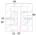
The invention relates to a windproof photovoltaic solar panel, which comprises a main body 11, wherein a fan blade cavity 32 is arranged in the main body 11, the upper wall of the fan blade cavity 32 is rotatably connected with a fan blade shaft 30, the outer circular surface of the fan blade shaft 30 is fixedly connected with fan blades 31, the left side and the right side of the fan blade cavity 32 are symmetrically communicated with air inlets 33, the air inlets 33 are communicated with the outside, a switching mechanism 101 is arranged on the upper side of the fan blade cavity 32, a trigger mechanism 102 is arranged on the upper side of the switching mechanism 101, the trigger mechanism 102 comprises a centrifugal cavity 48 arranged on the upper side of the fan blade cavity 32, the upper wall of the centrifugal cavity 48 is rotatably connected with a centrifugal turntable shaft threaded shaft 65, the lower end of the centrifugal turntable shaft threaded shaft 65 is fixedly connected with a centrifugal turntable 66, the lower end of the centrifugal turntable 66 is fixedly connected with an annular centrifugal clamping groove rod 67, the lower wall of the centrifugal cavity 48 is rotatably connected with a centrifugal turntable shaft, the centrifugal clamping groove rod 67 is close to the centrifugal clamping groove 59 which is symmetrically arranged on the left side and the right side of the centrifugal rotating seat 64 and has an opening close to the centrifugal clamping groove cavity 63 on one side of the centrifugal clamping groove rod 67, the clamping groove cavity 63 is internally provided with a clamping groove block 61 capable of sliding left and right, the lower side of the fan blade cavity 32 is provided with a cleaning mechanism 103, the upper side of the trigger mechanism 102 is provided with a control mechanism 104, the control mechanism 104 comprises a threaded shaft cavity 70 arranged on the upper side of the centrifugal cavity 48, the upper end of the centrifugal rotating disc shaft threaded shaft 65 extends into the threaded shaft cavity 70 and is rotatably connected with the upper wall of the threaded shaft 70, a threaded block 68 is fixedly connected to the outer circular surface of the centrifugal rotating disc shaft threaded shaft 65, threaded block grooves 69 are arranged on the left side and the right side of the threaded shaft 65 of the centrifugal rotating disc shaft 69, and a rod supporting cavity 26 positioned in the main body 11 is communicated with one side of the centrifugal rotating disc shaft, a support rod 25 capable of sliding up and down is arranged in the support rod cavity 26, and one end of the support rod 25 close to the centrifugal turntable shaft threaded shaft 65 extends into the threaded block groove 69.
Advantageously, a slot spring 62 is fixedly connected between an end surface of the slot block 61 remote from the centrifugal slot rod 67 and a wall of the slot block cavity 63 remote from the centrifugal slot rod 67.
Beneficially, a vertical moving rod cavity 45 is arranged on one side, away from the threaded shaft cavity 70, of the abutting rod cavity 26 in a communicated manner, one end, away from the threaded shaft cavity 70, of the abutting rod 25 extends into the vertical moving rod cavity 45 and is fixedly connected with a connecting rod 44, one side, away from the abutting rod cavity 26, of the connecting rod 44 is provided with a connecting rod cavity 50 which is opened and away from one side of the abutting rod cavity 26, a clamping block 41 capable of sliding left and right is arranged in the connecting rod cavity 50, one end, close to the abutting rod cavity 26, of the clamping block 41 is close to one end, close to the connecting rod cavity 50, of the abutting rod cavity 26, is fixedly connected with a clamping block spring 49, one side, away from the abutting rod cavity 26, of the vertical moving rod cavity 45 is arranged in a communicated manner, and is provided with an electromagnet cavity 43.
It is beneficial, it slides from top to bottom and is located to erect in the pole chamber 45 that moves the pole 16 that erects of connecting rod 44 upside, 11 upper end fixedly connected with fixed block 21 of main part, upside is equipped with about running through and the ascending turning block chamber 19 of opening about in the fixed block 21, the wall rotates around the turning block chamber 19 and is connected with axis of rotation 17, disc fixedly connected with turning block 20 outside axis of rotation 17, turning block 20 upper end fixedly connected with solar panel 13.
Beneficially, the main body 11 has an upper end face of the main body 12, and is provided with a through block cavity 18 which penetrates through the through block cavity from top to bottom, the vertical moving rod 16 penetrates through the through block cavity 18 and extends out of the through block cavity, the upper side of the vertical moving rod 16 is provided with a vertical moving rod through cavity 14 which penetrates through the through block cavity from left to right and has an upward opening, the vertical moving rod penetrates through the front wall and the rear wall of the through cavity 14 and is fixedly connected with a sliding chute block 24, the lower end of the solar panel 13 is provided with a sliding chute block 22 which is bilaterally symmetrical and fixedly connected with a sliding chute block 22, the sliding chute block 22 is provided with a through groove 23 which.
Beneficially, the switching mechanism 101 includes a sleeve cavity 15 disposed on the upper side of the vane cavity 32 and located on the lower side of the centrifugal cavity 48, the upper end of the vane shaft 30 extends into the sleeve cavity 15, the lower end of the centrifugal rotation seat shaft 60 extends into the sleeve cavity 15, a sleeve slider 57 capable of sliding up and down is disposed in the sleeve cavity 15, a sleeve 58 penetrating through the sleeve slider 57 up and down is sleeved on the lower end of the centrifugal rotation seat shaft 60 and the upper end of the vane shaft 30 together, and sleeve slider grooves 56 which are symmetrically disposed on the left side and the right side of the sleeve slider 57 and open towards the direction far away from the vane shaft 30 are disposed in the sleeve slider 57.
Beneficially, sleeve chute clamping block cavities 55 are communicated with the left side and the right side of the sleeve cavity 15, sleeve chute clamping blocks 54 capable of sliding left and right are arranged in the sleeve chute clamping block cavities 55, one side, far away from the sleeve cavity 15, of each sleeve chute clamping block cavity 55 is communicated with a connecting block cavity 53, a connecting block 51 capable of sliding left and right is arranged in each connecting block cavity 53, one end, far away from the sleeve cavity 15, of each sleeve chute clamping block 54 is fixedly connected with one end, close to the sleeve cavity 15, of each connecting block 51, one end face, close to the sleeve cavity 15, of each connecting block 51 is fixedly connected with a connecting block spring 52 between the walls, close to the sleeve cavity 15, of each connecting block cavity 53, one side, far away from the threaded shaft cavity 70, of each connecting block cavity 53 is communicated with a locking block cavity 46, the locking block cavities 46 are communicated with the vertical moving rod cavities 45, and locking blocks 47 capable, one end of the locking block 47, which is close to the sleeve cavity 15, is fixedly connected with one end of the connecting block 51, which is far away from the sleeve cavity 15.
Beneficially, cleaning mechanism 103 includes blade extending cavity 28 disposed on the lower side of blade cavity 32, the lower end of blade shaft 30 extends to blade extending cavity 28 and is fixedly connected with blade disc 27, outer circular surface of blade disc 27 is fixedly connected with toothed ring 29, one side of outer circle of toothed ring 29 is meshed with meshing toothed ring 36, outer circular surface of meshing toothed ring 36 is fixedly connected with blade holder 35, annular array on one side of outer circle of blade holder 35 is provided with blade cavity 34 with outward opening, blade cavity 34 is close to one side of meshing toothed ring 36 is communicated with blade centrifugal block cavity 38, blade centrifugal block cavity 38 is provided with slidable blade centrifugal block 37, one end of blade centrifugal block 37 is far away from meshing toothed ring 36 is fixedly connected with blade 40 capable of penetrating through blade cavity 34, blade centrifugal block 37 is far away from one end face of meshing toothed ring 36 and blade centrifugal block cavity 38 is far away from between one wall of meshing toothed ring 36 39.
The use steps herein are described in detail below with reference to fig. 1-5:
in the initial state, the right connecting block spring 52 is in a compressed state, and the solar panel 13 is high on the left and low on the right.
When strong wind occurs, wind enters the fan blade cavity 32 through the wind inlet 33 to drive the fan blade 31 to rotate, the fan blade 31 rotates to drive the fan blade shaft 30 to rotate, the fan blade shaft 30 rotates to drive the centrifugal rotating seat shaft 60 to rotate through the sleeve 58, the centrifugal rotating seat shaft 60 rotates to drive the centrifugal rotating seat 64 to rotate, the clamping groove block 61 moves outwards under the action of centrifugal force when the centrifugal rotating seat 64 rotates, the clamping groove block 61 is clamped in the centrifugal clamping groove 59 when the wind speed reaches a certain degree, at the same time, the clamping groove block 61 rotates to drive the centrifugal clamping groove rod 67 to rotate, the centrifugal rotating disk 66 known by the centrifugal clamping groove rod 67 rotates, the centrifugal rotating disk 66 rotates to drive the centrifugal rotating disk shaft threaded shaft 65 to rotate, the centrifugal rotating disk shaft threaded shaft 65 rotates forwards to drive the threaded block 68 to descend, the threaded block 68 descends through abutting to drive the left side abutting rod 25 to descend, the left side abutting rod 25 descends to drive the connecting rod 44 to descend, the, the left vertical moving rod 16 descends to drive the left sliding groove slide block 24 to descend, the left sliding groove slide block 24 descends to drive the left sliding groove block 22 to descend through the balance and drive the right sliding groove block 22 to ascend, the right sliding groove block 22 ascends to drive the right sliding groove slide block 24 to ascend through the balance, the right sliding groove slide block 24 ascends to drive the right vertical moving rod 16 to ascend, the right vertical moving rod 16 ascends to drive the right connecting rod 44 to ascend, when the right connecting rod 44 ascends until the solar panel 13 is parallel to the wind, the locking block 47 unlocks the locking block 47, the locking block 47 moves towards the direction close to the vertical moving rod cavity 45 and drives the connecting block 51 to move towards the direction close to the vertical moving rod cavity 45, the connecting block 51 moves to drive the sleeve sliding groove clamping block 54 to move towards the direction far away from the sleeve cavity 15, and the sleeve slide block 57 descends to drive the sleeve 58 to descend.
Meanwhile, the blade shaft 30 rotates to drive the blade disc 27 to rotate, the blade disc 27 rotates to drive the gear ring 29 to rotate, the gear ring 29 drives the meshing gear ring 36 to rotate through gear meshing, the meshing gear ring 36 rotates to drive the blade seat 35 to rotate, the blade seat 35 rotates to drive the blade centrifugal block 37 to rotate, the blade centrifugal block 37 rotates to drive the blade 40 to rotate, and meanwhile, the blade centrifugal block 37 moves away from the meshing gear ring 36 under the action of centrifugal force, so that the blade 40 extends out of the blade extension cavity 28 and cleans peripheral weeds.
The invention has the beneficial effects that: the solar panel can be automatically adjusted to be parallel to the wind when the wind speed is too high, the damage to the solar panel caused by the too high wind is reduced, the service life of the solar panel is shortened, meanwhile, weeds around the solar panel can be cleaned by means of the wind power, and the light absorption efficiency of the solar panel is prevented from being influenced by the too high growth of the weeds.
The above embodiments are merely illustrative of the technical ideas and features of the present invention, and the purpose thereof is to enable those skilled in the art to understand the contents of the present invention and implement the present invention, and not to limit the protection scope of the present invention. All equivalent changes and modifications made according to the spirit of the present invention should be covered within the protection scope of the present invention.
Claims (8)
1. The utility model provides a prevent wind photovoltaic solar panel, includes the main part, its characterized in that: the fan blade device is characterized in that a fan blade cavity is arranged in the main body, the upper wall of the fan blade cavity is rotationally connected with a fan blade shaft, the outer circular surface of the fan blade shaft is fixedly connected with fan blades, the left side and the right side of the fan blade cavity are symmetrically and communicated with air inlets, the air inlets are communicated with the outside, the upper side of the fan blade cavity is provided with a switching mechanism, the upper side of the switching mechanism is provided with a trigger mechanism, the trigger mechanism comprises a centrifugal cavity arranged on the upper side of the fan blade cavity, the upper wall of the centrifugal cavity is rotationally connected with a centrifugal turntable shaft threaded shaft, the lower end of the centrifugal turntable shaft threaded shaft is fixedly connected with a centrifugal turntable, the lower end of the centrifugal turntable is fixedly connected with an annular centrifugal clamping groove rod, the lower wall of the centrifugal cavity is rotationally connected with a centrifugal turntable shaft, the upper end of the centrifugal turntable shaft is fixedly connected with, the left side and the right side of the centrifugal rotary seat are symmetrically provided with clamping groove block cavities with openings close to one side of the centrifugal clamping groove rod, a clamping groove block capable of sliding left and right is arranged in the clamping groove block cavity, a cleaning mechanism is arranged at the lower side of the fan blade cavity, the upper side of the trigger mechanism is provided with a control mechanism, the control mechanism comprises a threaded shaft cavity arranged on the upper side of the centrifugal cavity, the upper end of the screw thread shaft of the centrifugal turntable shaft extends into the screw thread shaft cavity and is rotationally connected with the upper wall of the screw thread shaft cavity, the outer circle surface of the screw thread shaft of the centrifugal turntable shaft is fixedly connected with a screw thread block, the left side and the right side of the screw thread block are provided with screw thread block grooves, one side of the thread block groove, which is far away from the thread shaft of the centrifugal turntable shaft, is communicated with a support rod cavity positioned in the main body, the supporting rod capable of sliding up and down is arranged in the supporting rod cavity, and one end, close to the threaded shaft of the centrifugal turntable shaft, of the supporting rod extends into the threaded block groove.
2. The wind resistant photovoltaic solar panel of claim 1, wherein: a clamping groove spring is fixedly connected between one end face, far away from the centrifugal clamping groove rod, of the clamping groove block and one wall, far away from the centrifugal clamping groove rod, of the clamping groove block cavity.
3. The wind resistant photovoltaic solar panel of claim 1, wherein: the supporting rod cavity is far away from one side of the threaded shaft cavity, a vertical moving rod cavity is communicated and arranged, the supporting rod is far away from one end of the threaded shaft cavity and extends to the vertical moving rod cavity and is fixedly connected with a connecting rod, one side of the supporting rod cavity is far away from the connecting rod, an opening is formed in one side of the supporting rod cavity, a connecting rod cavity is arranged in the connecting rod cavity, a clamping block capable of sliding left and right is arranged in the connecting rod cavity, the clamping block is close to one end of the supporting rod cavity and the connecting rod cavity, a clamping block spring is fixedly connected between one wall of the supporting rod cavity, the vertical moving rod cavity is far away from one side of the supporting rod cavity, an electromagnet cavity is communicated and arranged, and the electromagnet cavity is.
4. The wind resistant photovoltaic solar panel of claim 1, wherein: erect and move the pole intracavity and be equipped with and slide from top to bottom and be located the perpendicular pole that moves of connecting rod upside, main part upper end fixedly connected with fixed block, the upside is equipped with about and runs through and the ascending turning block chamber of opening in the fixed block, the wall rotates before the turning block chamber and is connected with the axis of rotation, the disc fixedly connected with turning block outside the axis of rotation, turning block upper end fixedly connected with solar panel.
5. The wind resistant photovoltaic solar panel of claim 1, wherein: the solar panel comprises a main body upper end face and is characterized in that the main body upper end face is provided with a bilateral symmetry fixedly connected with through block, a through block cavity which penetrates through the through block from top to bottom is formed in the through block, a vertical moving rod penetrates through the through block cavity and extends out of the through block cavity, a left vertical moving rod which penetrates through the left side and the right side and is provided with an upward opening penetrates through the through cavity, a vertical moving rod penetrates through a sliding groove sliding block fixedly connected with the front wall and the rear wall of the through cavity, a solar panel lower end is provided with a bilateral symmetry fixedly connected with sliding groove block, a front through groove and.
6. The wind resistant photovoltaic solar panel of claim 1, wherein: switching mechanism is including locating fan blade chamber upside just is located the sleeve chamber of centrifugal chamber downside, fan blade epaxial end extends to the sleeve intracavity, centrifugation swivel mount axle lower extreme extends to the sleeve intracavity, the sleeve intracavity is equipped with gliding sleeve slider from top to bottom, centrifugation swivel mount axle lower extreme with the common cover in fan blade epaxial end is equipped with runs through from top to bottom the sleeve of sleeve slider, the bilateral symmetry be equipped with the opening in the sleeve slider to keeping away from the sleeve slider groove of fan blade axle direction.
7. The wind resistant photovoltaic solar panel of claim 1, wherein: the left side and the right side of the sleeve cavity are communicated with a sleeve chute clamping block cavity, a sleeve chute clamping block capable of sliding left and right is arranged in the sleeve chute clamping block cavity, a connecting block cavity is communicated with one side of the sleeve chute clamping block cavity, which is far away from the sleeve cavity, a connecting block capable of sliding left and right is arranged in the connecting block cavity, one end of the sleeve chute clamping block, which is far away from the sleeve cavity, is fixedly connected with one end of the connecting block, which is close to the sleeve cavity, a connecting block spring is fixedly connected between one end surface of the connecting block close to the sleeve cavity and one wall of the connecting block cavity close to the sleeve cavity, a locking block cavity is communicated with one side of the connecting block cavity, which is far away from the threaded shaft cavity, and is communicated with the vertical moving rod cavity, the locking block capable of sliding left and right is arranged in the locking block cavity, and one end of the sleeve cavity, close to the locking block, is far away from the connecting block and is fixedly connected with one end of the sleeve cavity.
8. The wind resistant photovoltaic solar panel of claim 1, wherein: the cleaning mechanism comprises a blade extending cavity arranged at the lower side of the fan blade cavity, the lower end of the fan blade shaft extends into the blade extending cavity and is fixedly connected with a blade disc, a gear ring is fixedly connected with the outer circular surface of the blade disc, one side of the outer circle of the gear ring is engaged with an engaging gear ring, the outer circle surface of the meshing gear ring is fixedly connected with a blade seat, one side of the outer circle of the blade seat is provided with blade cavities with outward openings in an annular array, a blade centrifugal block cavity is communicated with one side of the blade cavity close to the meshing gear ring, a blade centrifugal block capable of sliding is arranged in the blade centrifugal block cavity, one end of the blade centrifugal block, which is far away from the meshing gear ring, is fixedly connected with a blade which can penetrate through the blade cavity, and a blade centrifugal block spring is fixedly connected between one end surface of the blade centrifugal block, which is far away from the meshing toothed ring, and one wall of the blade centrifugal block cavity, which is far away from the meshing toothed ring.
Priority Applications (1)
| Application Number | Priority Date | Filing Date | Title |
|---|---|---|---|
| CN202011615297.4A CN112636675B (en) | 2020-12-30 | 2020-12-30 | Prevent wind photovoltaic solar panel |
Applications Claiming Priority (1)
| Application Number | Priority Date | Filing Date | Title |
|---|---|---|---|
| CN202011615297.4A CN112636675B (en) | 2020-12-30 | 2020-12-30 | Prevent wind photovoltaic solar panel |
Publications (2)
| Publication Number | Publication Date |
|---|---|
| CN112636675A true CN112636675A (en) | 2021-04-09 |
| CN112636675B CN112636675B (en) | 2022-09-16 |
Family
ID=75286985
Family Applications (1)
| Application Number | Title | Priority Date | Filing Date |
|---|---|---|---|
| CN202011615297.4A Active CN112636675B (en) | 2020-12-30 | 2020-12-30 | Prevent wind photovoltaic solar panel |
Country Status (1)
| Country | Link |
|---|---|
| CN (1) | CN112636675B (en) |
Citations (16)
| Publication number | Priority date | Publication date | Assignee | Title |
|---|---|---|---|---|
| KR20120024137A (en) * | 2010-09-06 | 2012-03-14 | 한국 전기안전공사 | Apparatus for preventing damage of tracking type photovoltaic panel support |
| CN108205908A (en) * | 2017-11-24 | 2018-06-26 | 潘荣静 | A kind of novel intelligent traffic indicating equipment |
| CN207994995U (en) * | 2018-01-26 | 2018-10-19 | 刘增宏 | A kind of solar panels Windproof protective device for pylon installation |
| CN110138324A (en) * | 2018-02-08 | 2019-08-16 | 申敏 | A kind of windproof solar panels of automatic adjustment |
| CN110957972A (en) * | 2020-01-03 | 2020-04-03 | 嵊州图白发电科技有限公司 | Rotary solar panel power generation device capable of being cleaned automatically |
| CN210578362U (en) * | 2019-08-02 | 2020-05-19 | 锦州华昌光伏科技有限公司 | Photovoltaic power generation device |
| CN111237131A (en) * | 2020-03-03 | 2020-06-05 | 诸暨亚目发动机有限公司 | Wind power generator device for storage and protection when wind speed is too high |
| CN111384891A (en) * | 2020-03-23 | 2020-07-07 | 杭州崔测科技有限公司 | Solar panel support structure based on rotary centrifugal force |
| CN111934614A (en) * | 2020-09-02 | 2020-11-13 | 福州鼓楼花旦净电子科技有限公司 | Automatic pollution-free photovoltaic power generation device who weeds |
| CN111990384A (en) * | 2020-09-10 | 2020-11-27 | 温州市晨绕机械科技有限公司 | Can follow wind height-adjusting's prevent wind type and spout pesticide dolly device |
| CN112019942A (en) * | 2020-09-07 | 2020-12-01 | 沈章梅 | 5G base station |
| CN112032663A (en) * | 2020-10-09 | 2020-12-04 | 天津昂熙灯具有限公司 | Windproof solar LED street lamp device capable of automatically adjusting gradient |
| CN112037677A (en) * | 2020-09-24 | 2020-12-04 | 青岛向帅广告科技有限公司 | Self-cleaning windproof self-descending LED (light emitting diode) billboard device |
| CN112032638A (en) * | 2020-09-15 | 2020-12-04 | 福州中天泰电子科技有限公司 | Energy-saving street lamp capable of being used in severe weather |
| CN112072994A (en) * | 2020-09-27 | 2020-12-11 | 申海宏 | Photovoltaic power generation device for renewable energy source convenient to adjust installation angle |
| CN112136582A (en) * | 2020-10-15 | 2020-12-29 | 临海市启致灯具有限公司 | Solar LED lamp device with temperature control function for greenhouse |
-
2020
- 2020-12-30 CN CN202011615297.4A patent/CN112636675B/en active Active
Patent Citations (16)
| Publication number | Priority date | Publication date | Assignee | Title |
|---|---|---|---|---|
| KR20120024137A (en) * | 2010-09-06 | 2012-03-14 | 한국 전기안전공사 | Apparatus for preventing damage of tracking type photovoltaic panel support |
| CN108205908A (en) * | 2017-11-24 | 2018-06-26 | 潘荣静 | A kind of novel intelligent traffic indicating equipment |
| CN207994995U (en) * | 2018-01-26 | 2018-10-19 | 刘增宏 | A kind of solar panels Windproof protective device for pylon installation |
| CN110138324A (en) * | 2018-02-08 | 2019-08-16 | 申敏 | A kind of windproof solar panels of automatic adjustment |
| CN210578362U (en) * | 2019-08-02 | 2020-05-19 | 锦州华昌光伏科技有限公司 | Photovoltaic power generation device |
| CN110957972A (en) * | 2020-01-03 | 2020-04-03 | 嵊州图白发电科技有限公司 | Rotary solar panel power generation device capable of being cleaned automatically |
| CN111237131A (en) * | 2020-03-03 | 2020-06-05 | 诸暨亚目发动机有限公司 | Wind power generator device for storage and protection when wind speed is too high |
| CN111384891A (en) * | 2020-03-23 | 2020-07-07 | 杭州崔测科技有限公司 | Solar panel support structure based on rotary centrifugal force |
| CN111934614A (en) * | 2020-09-02 | 2020-11-13 | 福州鼓楼花旦净电子科技有限公司 | Automatic pollution-free photovoltaic power generation device who weeds |
| CN112019942A (en) * | 2020-09-07 | 2020-12-01 | 沈章梅 | 5G base station |
| CN111990384A (en) * | 2020-09-10 | 2020-11-27 | 温州市晨绕机械科技有限公司 | Can follow wind height-adjusting's prevent wind type and spout pesticide dolly device |
| CN112032638A (en) * | 2020-09-15 | 2020-12-04 | 福州中天泰电子科技有限公司 | Energy-saving street lamp capable of being used in severe weather |
| CN112037677A (en) * | 2020-09-24 | 2020-12-04 | 青岛向帅广告科技有限公司 | Self-cleaning windproof self-descending LED (light emitting diode) billboard device |
| CN112072994A (en) * | 2020-09-27 | 2020-12-11 | 申海宏 | Photovoltaic power generation device for renewable energy source convenient to adjust installation angle |
| CN112032663A (en) * | 2020-10-09 | 2020-12-04 | 天津昂熙灯具有限公司 | Windproof solar LED street lamp device capable of automatically adjusting gradient |
| CN112136582A (en) * | 2020-10-15 | 2020-12-29 | 临海市启致灯具有限公司 | Solar LED lamp device with temperature control function for greenhouse |
Also Published As
| Publication number | Publication date |
|---|---|
| CN112636675B (en) | 2022-09-16 |
Similar Documents
| Publication | Publication Date | Title |
|---|---|---|
| CN112178567B (en) | Self-cleaning solar LED street lamp with rainwater power generation function | |
| CN112661223A (en) | Wind power generation-based seawater desalination device with linkage mixing function | |
| CN112032663A (en) | Windproof solar LED street lamp device capable of automatically adjusting gradient | |
| CN112636675B (en) | Prevent wind photovoltaic solar panel | |
| CN109259656A (en) | A kind of intelligence glass-cleaning robot | |
| CN110985297B (en) | Adjustable wind power generation device with brake | |
| CN112576447A (en) | Automatic reversing wind-driven generator | |
| CN108799153B (en) | Fan lamp | |
| CN215232753U (en) | Building engineering construction dust collector | |
| CN112205278A (en) | Energy-saving irrigation equipment utilizing wind energy and solar energy | |
| CN210686203U (en) | Special wind power generation tower for wind power plant | |
| CN112360320A (en) | Solar panel curtain capable of automatically adjusting illumination angle | |
| CN111998289A (en) | Energy-saving illuminating lamp for rainy and foggy weather | |
| CN208594396U (en) | Clothes hanger | |
| CN108515425B (en) | Silicon chip grinding device that formula of drawing can stabilize and polish | |
| CN111140436A (en) | Wind motor for irrigation | |
| CN111010073A (en) | Automatic solar panel who goes up and down | |
| CN218276560U (en) | Self-adjusting photovoltaic support | |
| CN111464124B (en) | Photovoltaic power generation board of adjustable photic angle | |
| CN213827225U (en) | A surely neat device for production of stainless steel head | |
| CN210584700U (en) | High-speed dispersion machine for producing silicon modified bi-component high-temperature-resistant paint | |
| CN213547432U (en) | Adjustable photovoltaic support | |
| CN219821708U (en) | Solar fishing boat Beidou positioner | |
| CN215566782U (en) | Adjustable sun-shading fan for outdoor engineering machinery | |
| CN215895271U (en) | Solar thermal engineering PLC control device |
Legal Events
| Date | Code | Title | Description |
|---|---|---|---|
| PB01 | Publication | ||
| PB01 | Publication | ||
| SE01 | Entry into force of request for substantive examination | ||
| SE01 | Entry into force of request for substantive examination | ||
| TA01 | Transfer of patent application right |
Effective date of registration: 20220826 Address after: No. 8, Xicheng Street, Economic Development Zone, Raoyang County, Hengshui City, Hebei Province, 053000 Applicant after: Zhongrun Smart Technology Electronics Hebei Co.,Ltd. Address before: 050035 No.69 Xueyuan Road, Yuhua District, Shijiazhuang City, Hebei Province Applicant before: Shijiazhuang paimeng Technology Co.,Ltd. |
|
| TA01 | Transfer of patent application right | ||
| GR01 | Patent grant | ||
| GR01 | Patent grant |