Medical treatment of full mechanical design of independent driving source is with warping nursing bed
Technical Field
The invention relates to a medical nursing bed, in particular to a medical deformation nursing bed with a single driving source and a full mechanical design.
Background
A nursing bed, which is a hospital bed used by a patient who is inconvenient to move in hospital or at home for nursing; for example, it is suitable for paralyzed patients, postoperative patients, patients with various physiological problems, bedridden patients, or other patients with inconvenient actions.
Traditional medical care bed is fixed knot structure, the flexibility is not enough, along with technical development, although the nursing bed that has upper portion lifting structure has appeared, but the function singleness, in actual nursing process, patient's the rising needs medical personnel supplementary, it is very hard, when the patient feeds, need medical personnel to feed, nursing personnel hold up food for a long time and feed, lead to the hand tired, when needing to provide an automatic support patient waist and sit up, with the automatic nursing bed structure of transferring the table to the patient in front of.
As such, further improvements are needed in the existing medical care beds.
Disclosure of Invention
The invention aims to provide a medical deformation nursing bed with a single drive source and a full mechanical design, which can automatically lift the waist of a patient to sit up and automatically transfer a table plate to the front of the patient.
In order to achieve the purpose, the invention adopts the following scheme:
a medical deformation nursing bed with an independent driving source and a full-mechanical design comprises a base, wherein a frame body is arranged on the base, a main beam rod is hinged to the frame body, a driving assembly used for driving the main beam rod to swing up and down is arranged on the base, the driving assembly is connected with the main beam rod, a supporting cross rod is arranged on the frame body, a first hinge seat, a second hinge seat and a third hinge seat are sequentially arranged on the supporting cross rod from left to right, a leg supporting plate is hinged to the first hinge seat, a hip supporting plate is hinged to the second hinge seat, and a waist supporting plate is hinged to the third hinge seat;
a fourth hinge seat, a fifth hinge seat and a sixth hinge seat are sequentially arranged on the main beam rod from left to right, a seventh hinge seat is arranged on the leg supporting plate, an eighth hinge seat is arranged on the hip supporting plate, a ninth hinge seat is arranged on the waist supporting plate, a first connecting rod is hinged between the fourth hinge seat and the seventh hinge seat, a second connecting rod is hinged between the fifth hinge seat and the eighth hinge seat, and a third connecting rod is hinged between the sixth hinge seat and the ninth hinge seat;
the utility model discloses a support body, including support body, table, first horizontal axis, first parallel connecting rod, first parallel hinged seat, second parallel hinged seat, first parallel connecting rod, second parallel hinged seat, first parallel hinged seat, second articulated seat, first articulated ball cover, main beam pole, first articulated ball cover, second articulated ball cover, first articulated ball and the second articulated ball is connected with the connecting axle between the articulated ball of first articulated ball cover.
Further, drive assembly is including setting up tenth articulated seat on the base, it has the push rod motor to articulate on the tenth articulated seat, main beam pole lower surface is provided with eleventh articulated seat, the output of push rod motor with eleventh articulated seat articulates.
Further, the main beam rod and the push rod motor are arranged towards the opposite side direction.
Further, the support rail is disposed above the main rail bar.
Further, the air conditioner is provided with a fan,
the bottom of the leg supporting plate close to the right side is hinged and overturned with the first hinge seat;
the right side edge of the hip supporting plate is hinged and overturned with the second hinge seat;
the left edge of the lumbar support plate and the third hinge seat are hinged and turned.
Further, the air conditioner is provided with a fan,
the seventh hinging seat is arranged on the right side of the lower surface of the leg supporting plate, and the seventh hinging seat is arranged on the right side relative to the first hinging seat;
the eighth hinged seat is arranged in the middle of the lower surface of the hip supporting plate and is arranged on the left side relative to the second hinged seat;
the ninth hinge seat is arranged in the middle of the lower surface of the waist supporting plate, and the ninth hinge seat is arranged on the right side of the third hinge seat.
Further, the axial distance between the first transverse shaft and the second transverse shaft is equal to the axial distance between the first parallel hinge seat and the second parallel hinge seat, the first parallel connecting rod and the second parallel connecting rod are the same in length, and the first parallel connecting rod and the second parallel connecting rod are arranged in parallel.
Further, a pillow used for increasing the comfort of the head of a patient is arranged on the waist supporting plate.
Furthermore, a cup groove for placing a cup is formed in the table plate.
Furthermore, cotton pads are arranged on the upper surfaces of the leg supporting plate, the hip supporting plate and the waist supporting plate respectively.
In summary, compared with the prior art, the invention has the beneficial effects that:
the invention solves the defects of the existing nursing bed, and has the following advantages:
1. the patient lying down can be quickly switched to a sitting state, so that the patient can conveniently take food or move, the labor force for lifting up by medical staff is saved, and the lifting up efficiency is higher;
2. when the nursing bed switches the patient into the sitting-up state, the table plate is automatically displayed in front of the patient, the sitting-up patient can conveniently eat by using the table plate, and the patient can use the table plate to operate other things after sitting up, so that the fatigue degree of the medical personnel for supporting food by hands is reduced, and the fatigue degree is greatly reduced;
3. the nursing bed has the advantages that a plurality of actions are realized through the structure of the nursing bed, all deformation actions are completed by using one driving source, a great breakthrough is made in the technology, the nursing bed can be freely changed in two shapes, the actions which can be completed only by using an angle driving source in the past are completed, and the manufacturing cost is saved.
And the structure is simple, and the use is convenient.
Drawings
FIG. 1 is a perspective view of the present invention in a first use state;
FIG. 2 is a perspective view of the present invention in a second use state;
FIG. 3 is a perspective view of a third use state of the present invention;
FIG. 4 is an enlarged view of a portion of FIG. 2 in accordance with the present invention;
FIG. 5 is a front view of the present invention in a first use state;
FIG. 6 is a front view of the present invention in a second use state;
FIG. 7 is a front view of a third use state of the present invention;
FIG. 8 is a left side view of a first use state of the present invention;
FIG. 9 is a cross-sectional view taken along line B-B of FIG. 8;
FIG. 10 is a left side view of a second use state of the present invention;
FIG. 11 is a cross-sectional view taken along line B-B of FIG. 10;
FIG. 12 is a left side view of a third use state of the present invention;
FIG. 13 is a cross-sectional view taken along line D-D of FIG. 12;
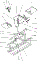
FIG. 14 is one of the exploded views of the present invention;
fig. 15 is a second exploded view of the present invention.
Detailed Description
The technical solutions in the embodiments of the present invention will be clearly and completely described below with reference to the drawings in the embodiments of the present invention, and it is obvious that the described embodiments are only a part of the embodiments of the present invention, and not all of the embodiments. All other embodiments, which can be derived by a person skilled in the art from the embodiments given herein without making any creative effort, shall fall within the protection scope of the present invention.
Referring to FIGS. 1-15, the present invention provides
A medical treatment deformation nursing bed with an independent driving source and a full mechanical design comprises a base 1, wherein a frame body 2 is arranged on the base 1, a main beam rod 3 is hinged to the frame body 2, a driving assembly 4 used for driving the main beam rod 3 to swing up and down is arranged on the base 1, the driving assembly 4 is connected with the main beam rod 3, a supporting cross rod 5 is arranged on the frame body 2, a first hinging seat 6, a second hinging seat 7 and a third hinging seat 8 are sequentially arranged on the supporting cross rod 5 from left to right, a leg supporting plate 9 is hinged to the first hinging seat 6, a hip supporting plate 10 is hinged to the second hinging seat 7, and a waist supporting plate 11 is hinged to the third hinging seat 8;
a fourth hinge seat 12, a fifth hinge seat 13 and a sixth hinge seat 14 are sequentially arranged on the main beam rod 3 from left to right, a seventh hinge seat 15 is arranged on the leg supporting plate 9, an eighth hinge seat 16 is arranged on the hip supporting plate 10, a ninth hinge seat 17 is arranged on the waist supporting plate 11, a first connecting rod 18 is hinged between the fourth hinge seat 12 and the seventh hinge seat 15, a second connecting rod 19 is hinged between the fifth hinge seat 13 and the eighth hinge seat 16, and a third connecting rod 20 is hinged between the sixth hinge seat 14 and the ninth hinge seat 17;
a first transverse shaft 21 and a second transverse shaft 210 are respectively arranged at two sides of the frame body 2, a first parallel connecting rod 22 is hinged on the first transverse shaft 21, a second parallel connecting rod 23 is hinged on the second transverse shaft 210, a table plate 24 is arranged above the first transverse shaft 21, the table plate 24 is provided with a first parallel hinge seat 25 and a second parallel hinge seat 26, the outer end of the first parallel connecting rod 22 is hinged with the first parallel hinge seat 25, the outer end of the second parallel connecting rod 23 is hinged with the second parallel hinge seat 26, a first hinge ball sleeve 27 is arranged on the second parallel connecting rod 23, a second hinge ball sleeve 28 is respectively arranged on two side walls of the main beam rod 3, a first hinge ball 29 is hinged in the first hinge ball sleeve 27, a second hinge ball 30 is hinged in the second hinge ball sleeve 28, a connecting shaft 31 is connected between the first hinging ball 29 and the second hinging ball 30;
the working principle of the structure is as follows:
the nursing bed has two forms;
the first mode is as follows: the leg supporting plate 9, the hip supporting plate 10 and the waist supporting plate 11 are horizontally arranged to form a bed body state, so that a lying space is provided for a patient, and the table plates 24 are arranged at two sides of the nursing bed, so that medical articles or other articles can be conveniently stored when the nursing bed is not used;
the second mode is as follows: leg support plate 9, buttock support plate 10 and waist support plate 11 warp, form the form of seat, and the patient that will lie down simultaneously switches into the state of sitting up fast, and at leg support plate 9, buttock support plate 10 and waist support plate 11 deformation process simultaneously, the table 24 automatic movement of both sides is in front of the patient, and the patient after sitting up forms a usable completion desk of can having a dinner in front.
The nursing bed of the invention adopts two form structure switching principles:
the process of transforming the nursing bed in the first shape into the nursing bed in the second shape is as follows:
the driving assembly 4 is used for driving the main beam rod 3 to swing up and down on one side of the frame body 2, and after the driving assembly 4 is started, the driving assembly drives the main beam rod 3 to swing upwards in the swinging process of the main beam rod 3; the first connecting rod 18 drives the leg support plate 9 to turn downwards around the first hinge seat 6 to form a leg leaning plate; the second connecting rod 19 pushes upwards to drive the hip support plate 10 to turn upwards for a short distance around the second hinge seat 7 to form the hip support plate; the third connecting rod 20 pushes upward to drive the waist supporting plate 11 to turn upward around the third hinge seat 8 to form a backrest plate; lifting the patient;
the actions performed synchronously at this time are: the table plates 24 on the two sides are drawn inwards;
in the process of upward turning of the main beam rod 3, the second hinged ball sleeves 28 on the two sides are lifted horizontally, in the process of lifting the second hinged ball sleeves 28, the second parallel connecting rods 23 turned outwards are pressed by the connecting shafts 31, so that the second parallel connecting rods 23 are turned inwards, at the moment, the first parallel connecting rods 22 and the second parallel connecting rods 23 are synchronously turned inwards, the horizontal state of the table plate 24 is ensured in the turning process, the table plate 24 is slowly drawn inwards, the drawing process is kept horizontal, and the table surface articles are prevented from falling;
the process of transforming the nursing bed in the second shape into the nursing bed in the first shape is contrary to the above description:
it should be noted that, the above actions are completed by using one driving source, so that the design is reasonable, and the manufacturing cost is saved.
The driving assembly 4 comprises a tenth hinge seat 401 arranged on the base 1, a push rod motor 402 is hinged on the tenth hinge seat 401, an eleventh hinge seat 403 is arranged on the lower surface of the main beam rod 3, and the output end of the push rod motor 402 is hinged with the eleventh hinge seat 403;
the structure of the driving assembly 4 is provided, the state switching of the nursing bed is completed by controlling the extension and retraction of the push rod motor 402, and the main beam rod 3 is turned upwards when the push rod motor 402 extends outwards.
The main beam 3 and the push rod motor 402 of the present invention are disposed in opposite directions.
The support rail 5 of the present invention is disposed above the main beam bar 3.
The bottom of the leg supporting plate 9 close to the right side is hinged and overturned with the first hinge seat 6; the right side edge of the hip supporting plate 10 is hinged and overturned with the second hinge seat 7; the left side edge of the waist supporting plate 11 and the third hinge seat 8 are hinged and turned.
The seventh hinge base 15 of the present invention is disposed at the right side of the lower surface of the leg support plate 9, and the seventh hinge base 15 is disposed at the right side with respect to the first hinge base 6; the eighth hinge seat 16 is provided at a middle position of a lower surface of the hip support plate 10, and the eighth hinge seat 16 is provided at a left side with respect to the second hinge seat 7; the ninth hinge seat 17 is disposed at a middle position of a lower surface of the lumbar support plate 11, and the ninth hinge seat 17 is disposed at a right side with respect to the third hinge seat 8.
According to the invention, the axial distance between the first transverse shaft 21 and the second transverse shaft 210 is equal to the axial distance between the first parallel hinge seat 25 and the second parallel hinge seat 26, the first parallel connecting rod 22 and the second parallel connecting rod 23 are the same in length, and the first parallel connecting rod 22 and the second parallel connecting rod 23 are arranged in parallel.
The lumbar support plate 11 of the present invention is provided with a pillow 100 for increasing the comfort of the head of a patient.
The table plate 24 is provided with a cup groove for placing a cup.
The upper surfaces of the leg supporting plate 9, the hip supporting plate 10 and the waist supporting plate 11 are respectively provided with cotton pads, so that the comfort level is increased.
While there have been shown and described the fundamental principles and principal features of the invention and advantages thereof, it will be understood by those skilled in the art that the invention is not limited by the embodiments described above, which are given by way of illustration of the principles of the invention, but is susceptible to various changes and modifications without departing from the spirit and scope of the invention as defined by the appended claims. The scope of the invention is defined by the appended claims and equivalents thereof.