CN112567837A - Resource management for 5G eV2X - Google Patents
Resource management for 5G eV2X Download PDFInfo
- Publication number
- CN112567837A CN112567837A CN201980052994.2A CN201980052994A CN112567837A CN 112567837 A CN112567837 A CN 112567837A CN 201980052994 A CN201980052994 A CN 201980052994A CN 112567837 A CN112567837 A CN 112567837A
- Authority
- CN
- China
- Prior art keywords
- resources
- resource
- sidelink
- data packet
- determining
- Prior art date
- Legal status (The legal status is an assumption and is not a legal conclusion. Google has not performed a legal analysis and makes no representation as to the accuracy of the status listed.)
- Pending
Links
- 238000000034 method Methods 0.000 claims abstract description 74
- 230000005540 biological transmission Effects 0.000 claims description 168
- 238000004891 communication Methods 0.000 claims description 120
- 238000005259 measurement Methods 0.000 claims description 68
- 230000000737 periodic effect Effects 0.000 claims description 63
- 230000015654 memory Effects 0.000 claims description 28
- 238000003860 storage Methods 0.000 claims description 22
- 238000013468 resource allocation Methods 0.000 abstract description 59
- 238000007726 management method Methods 0.000 abstract description 16
- 230000004044 response Effects 0.000 description 70
- 230000006870 function Effects 0.000 description 50
- 238000005516 engineering process Methods 0.000 description 30
- 238000013507 mapping Methods 0.000 description 22
- 230000008569 process Effects 0.000 description 19
- 230000001960 triggered effect Effects 0.000 description 16
- 102100030800 Ras suppressor protein 1 Human genes 0.000 description 10
- 101000741965 Homo sapiens Inactive tyrosine-protein kinase PRAG1 Proteins 0.000 description 9
- 102100038659 Inactive tyrosine-protein kinase PRAG1 Human genes 0.000 description 9
- 238000010586 diagram Methods 0.000 description 9
- 101001137642 Homo sapiens Kinase suppressor of Ras 1 Proteins 0.000 description 8
- 102100021001 Kinase suppressor of Ras 1 Human genes 0.000 description 8
- GVVPGTZRZFNKDS-JXMROGBWSA-N geranyl diphosphate Chemical compound CC(C)=CCC\C(C)=C\CO[P@](O)(=O)OP(O)(O)=O GVVPGTZRZFNKDS-JXMROGBWSA-N 0.000 description 8
- 230000002093 peripheral effect Effects 0.000 description 8
- 101100148830 Arabidopsis thaliana SCI1 gene Proteins 0.000 description 7
- 101000636109 Homo sapiens Ras suppressor protein 1 Proteins 0.000 description 7
- 101100054266 Saccharomyces cerevisiae (strain ATCC 204508 / S288c) SNF4 gene Proteins 0.000 description 7
- 238000005304 joining Methods 0.000 description 7
- 238000012986 modification Methods 0.000 description 7
- 230000004048 modification Effects 0.000 description 7
- 238000012544 monitoring process Methods 0.000 description 7
- 238000013461 design Methods 0.000 description 6
- 238000012545 processing Methods 0.000 description 6
- 238000001228 spectrum Methods 0.000 description 5
- 230000001413 cellular effect Effects 0.000 description 4
- 241000760358 Enodes Species 0.000 description 3
- 101710102668 Ras suppressor protein 1 Proteins 0.000 description 3
- 230000004913 activation Effects 0.000 description 3
- 238000001514 detection method Methods 0.000 description 3
- 230000007246 mechanism Effects 0.000 description 3
- 230000003287 optical effect Effects 0.000 description 3
- 230000011664 signaling Effects 0.000 description 3
- 230000000007 visual effect Effects 0.000 description 3
- 101100368081 Neurospora crassa (strain ATCC 24698 / 74-OR23-1A / CBS 708.71 / DSM 1257 / FGSC 987) sym-1 gene Proteins 0.000 description 2
- 238000003491 array Methods 0.000 description 2
- 238000013475 authorization Methods 0.000 description 2
- 230000015572 biosynthetic process Effects 0.000 description 2
- 230000008859 change Effects 0.000 description 2
- 239000003795 chemical substances by application Substances 0.000 description 2
- 230000009849 deactivation Effects 0.000 description 2
- 230000003247 decreasing effect Effects 0.000 description 2
- PCHJSUWPFVWCPO-UHFFFAOYSA-N gold Chemical group [Au] PCHJSUWPFVWCPO-UHFFFAOYSA-N 0.000 description 2
- 230000036541 health Effects 0.000 description 2
- 230000007774 longterm Effects 0.000 description 2
- 230000001360 synchronised effect Effects 0.000 description 2
- 238000012546 transfer Methods 0.000 description 2
- 101100201948 Arabidopsis thaliana RUS2 gene Proteins 0.000 description 1
- 101100127891 Caenorhabditis elegans let-4 gene Proteins 0.000 description 1
- 241000700159 Rattus Species 0.000 description 1
- 206010039203 Road traffic accident Diseases 0.000 description 1
- 230000003213 activating effect Effects 0.000 description 1
- 230000003044 adaptive effect Effects 0.000 description 1
- 238000004873 anchoring Methods 0.000 description 1
- 230000003466 anti-cipated effect Effects 0.000 description 1
- 230000003190 augmentative effect Effects 0.000 description 1
- 230000003139 buffering effect Effects 0.000 description 1
- 238000012790 confirmation Methods 0.000 description 1
- 238000013523 data management Methods 0.000 description 1
- 238000012217 deletion Methods 0.000 description 1
- 230000037430 deletion Effects 0.000 description 1
- 238000011161 development Methods 0.000 description 1
- 238000009826 distribution Methods 0.000 description 1
- 238000004134 energy conservation Methods 0.000 description 1
- 239000000835 fiber Substances 0.000 description 1
- 239000000446 fuel Substances 0.000 description 1
- 230000003993 interaction Effects 0.000 description 1
- 238000002955 isolation Methods 0.000 description 1
- 239000004973 liquid crystal related substance Substances 0.000 description 1
- 230000005055 memory storage Effects 0.000 description 1
- 238000013508 migration Methods 0.000 description 1
- 230000005012 migration Effects 0.000 description 1
- 238000010295 mobile communication Methods 0.000 description 1
- 238000005457 optimization Methods 0.000 description 1
- 230000009467 reduction Effects 0.000 description 1
- 238000012772 sequence design Methods 0.000 description 1
- 230000007480 spreading Effects 0.000 description 1
- 238000003892 spreading Methods 0.000 description 1
- 230000003068 static effect Effects 0.000 description 1
- 101150065184 sym-2 gene Proteins 0.000 description 1
- 230000026676 system process Effects 0.000 description 1
- 238000012549 training Methods 0.000 description 1
- 238000013519 translation Methods 0.000 description 1
Images


Classifications
-
- H—ELECTRICITY
- H04—ELECTRIC COMMUNICATION TECHNIQUE
- H04W—WIRELESS COMMUNICATION NETWORKS
- H04W72/00—Local resource management
- H04W72/02—Selection of wireless resources by user or terminal
-
- H—ELECTRICITY
- H04—ELECTRIC COMMUNICATION TECHNIQUE
- H04B—TRANSMISSION
- H04B17/00—Monitoring; Testing
- H04B17/30—Monitoring; Testing of propagation channels
- H04B17/309—Measuring or estimating channel quality parameters
- H04B17/318—Received signal strength
-
- H—ELECTRICITY
- H04—ELECTRIC COMMUNICATION TECHNIQUE
- H04L—TRANSMISSION OF DIGITAL INFORMATION, e.g. TELEGRAPHIC COMMUNICATION
- H04L1/00—Arrangements for detecting or preventing errors in the information received
- H04L1/08—Arrangements for detecting or preventing errors in the information received by repeating transmission, e.g. Verdan system
-
- H—ELECTRICITY
- H04—ELECTRIC COMMUNICATION TECHNIQUE
- H04L—TRANSMISSION OF DIGITAL INFORMATION, e.g. TELEGRAPHIC COMMUNICATION
- H04L1/00—Arrangements for detecting or preventing errors in the information received
- H04L1/12—Arrangements for detecting or preventing errors in the information received by using return channel
- H04L1/16—Arrangements for detecting or preventing errors in the information received by using return channel in which the return channel carries supervisory signals, e.g. repetition request signals
- H04L1/18—Automatic repetition systems, e.g. Van Duuren systems
- H04L1/1812—Hybrid protocols; Hybrid automatic repeat request [HARQ]
- H04L1/1819—Hybrid protocols; Hybrid automatic repeat request [HARQ] with retransmission of additional or different redundancy
-
- H—ELECTRICITY
- H04—ELECTRIC COMMUNICATION TECHNIQUE
- H04L—TRANSMISSION OF DIGITAL INFORMATION, e.g. TELEGRAPHIC COMMUNICATION
- H04L1/00—Arrangements for detecting or preventing errors in the information received
- H04L1/12—Arrangements for detecting or preventing errors in the information received by using return channel
- H04L1/16—Arrangements for detecting or preventing errors in the information received by using return channel in which the return channel carries supervisory signals, e.g. repetition request signals
- H04L1/18—Automatic repetition systems, e.g. Van Duuren systems
- H04L1/1829—Arrangements specially adapted for the receiver end
- H04L1/1861—Physical mapping arrangements
-
- H—ELECTRICITY
- H04—ELECTRIC COMMUNICATION TECHNIQUE
- H04L—TRANSMISSION OF DIGITAL INFORMATION, e.g. TELEGRAPHIC COMMUNICATION
- H04L1/00—Arrangements for detecting or preventing errors in the information received
- H04L1/12—Arrangements for detecting or preventing errors in the information received by using return channel
- H04L1/16—Arrangements for detecting or preventing errors in the information received by using return channel in which the return channel carries supervisory signals, e.g. repetition request signals
- H04L1/18—Automatic repetition systems, e.g. Van Duuren systems
- H04L1/1867—Arrangements specially adapted for the transmitter end
- H04L1/1887—Scheduling and prioritising arrangements
-
- H—ELECTRICITY
- H04—ELECTRIC COMMUNICATION TECHNIQUE
- H04L—TRANSMISSION OF DIGITAL INFORMATION, e.g. TELEGRAPHIC COMMUNICATION
- H04L1/00—Arrangements for detecting or preventing errors in the information received
- H04L1/12—Arrangements for detecting or preventing errors in the information received by using return channel
- H04L1/16—Arrangements for detecting or preventing errors in the information received by using return channel in which the return channel carries supervisory signals, e.g. repetition request signals
- H04L1/18—Automatic repetition systems, e.g. Van Duuren systems
- H04L1/1867—Arrangements specially adapted for the transmitter end
- H04L1/1896—ARQ related signaling
-
- H—ELECTRICITY
- H04—ELECTRIC COMMUNICATION TECHNIQUE
- H04W—WIRELESS COMMUNICATION NETWORKS
- H04W24/00—Supervisory, monitoring or testing arrangements
- H04W24/10—Scheduling measurement reports ; Arrangements for measurement reports
-
- H—ELECTRICITY
- H04—ELECTRIC COMMUNICATION TECHNIQUE
- H04W—WIRELESS COMMUNICATION NETWORKS
- H04W28/00—Network traffic management; Network resource management
- H04W28/16—Central resource management; Negotiation of resources or communication parameters, e.g. negotiating bandwidth or QoS [Quality of Service]
- H04W28/26—Resource reservation
-
- H—ELECTRICITY
- H04—ELECTRIC COMMUNICATION TECHNIQUE
- H04W—WIRELESS COMMUNICATION NETWORKS
- H04W4/00—Services specially adapted for wireless communication networks; Facilities therefor
- H04W4/30—Services specially adapted for particular environments, situations or purposes
- H04W4/40—Services specially adapted for particular environments, situations or purposes for vehicles, e.g. vehicle-to-pedestrians [V2P]
- H04W4/44—Services specially adapted for particular environments, situations or purposes for vehicles, e.g. vehicle-to-pedestrians [V2P] for communication between vehicles and infrastructures, e.g. vehicle-to-cloud [V2C] or vehicle-to-home [V2H]
-
- H—ELECTRICITY
- H04—ELECTRIC COMMUNICATION TECHNIQUE
- H04W—WIRELESS COMMUNICATION NETWORKS
- H04W72/00—Local resource management
- H04W72/04—Wireless resource allocation
- H04W72/044—Wireless resource allocation based on the type of the allocated resource
- H04W72/0446—Resources in time domain, e.g. slots or frames
-
- H—ELECTRICITY
- H04—ELECTRIC COMMUNICATION TECHNIQUE
- H04W—WIRELESS COMMUNICATION NETWORKS
- H04W72/00—Local resource management
- H04W72/04—Wireless resource allocation
- H04W72/044—Wireless resource allocation based on the type of the allocated resource
- H04W72/0453—Resources in frequency domain, e.g. a carrier in FDMA
-
- H—ELECTRICITY
- H04—ELECTRIC COMMUNICATION TECHNIQUE
- H04W—WIRELESS COMMUNICATION NETWORKS
- H04W72/00—Local resource management
- H04W72/20—Control channels or signalling for resource management
-
- H—ELECTRICITY
- H04—ELECTRIC COMMUNICATION TECHNIQUE
- H04W—WIRELESS COMMUNICATION NETWORKS
- H04W72/00—Local resource management
- H04W72/50—Allocation or scheduling criteria for wireless resources
- H04W72/51—Allocation or scheduling criteria for wireless resources based on terminal or device properties
-
- H—ELECTRICITY
- H04—ELECTRIC COMMUNICATION TECHNIQUE
- H04W—WIRELESS COMMUNICATION NETWORKS
- H04W80/00—Wireless network protocols or protocol adaptations to wireless operation
- H04W80/02—Data link layer protocols
-
- H—ELECTRICITY
- H04—ELECTRIC COMMUNICATION TECHNIQUE
- H04W—WIRELESS COMMUNICATION NETWORKS
- H04W92/00—Interfaces specially adapted for wireless communication networks
- H04W92/16—Interfaces between hierarchically similar devices
- H04W92/18—Interfaces between hierarchically similar devices between terminal devices
-
- H—ELECTRICITY
- H04—ELECTRIC COMMUNICATION TECHNIQUE
- H04L—TRANSMISSION OF DIGITAL INFORMATION, e.g. TELEGRAPHIC COMMUNICATION
- H04L1/00—Arrangements for detecting or preventing errors in the information received
- H04L1/12—Arrangements for detecting or preventing errors in the information received by using return channel
- H04L1/16—Arrangements for detecting or preventing errors in the information received by using return channel in which the return channel carries supervisory signals, e.g. repetition request signals
- H04L1/18—Automatic repetition systems, e.g. Van Duuren systems
- H04L1/1822—Automatic repetition systems, e.g. Van Duuren systems involving configuration of automatic repeat request [ARQ] with parallel processes
-
- H—ELECTRICITY
- H04—ELECTRIC COMMUNICATION TECHNIQUE
- H04W—WIRELESS COMMUNICATION NETWORKS
- H04W72/00—Local resource management
- H04W72/20—Control channels or signalling for resource management
- H04W72/23—Control channels or signalling for resource management in the downlink direction of a wireless link, i.e. towards a terminal
Abstract
Methods and systems for resource management on a sidelink of a vehicle to everything (V2X) scenario are disclosed. Example methods and systems for resource structures on sidelink are disclosed. The control channel and the data channel may be frequency division multiplexed (FDMed) or time division multiplexed (TDMed) using Orthogonal Frequency Division Multiplexed (OFDM) waveforms. Example methods and systems for resource configuration on a sidelink are disclosed. The resource configuration may be statically configured or may be locally configured. Example methods and systems for secondary resource allocation are disclosed. The secondary sensing may be performed by a group leader or RSU, and the local scheduling may be performed by the group leader or RSU.
Description
Background
With significant advances in "vehicle-to-everything" (V2X) applications, for basic safety, the transmission of short messages regarding the vehicle's own state data may need to be extended with the transmission of larger messages containing raw sensor data, the vehicle's intent data, coordination, confirmation of future maneuvers, etc. For these advanced applications, the expected requirements for meeting required data rates, latency, reliability, communication range and speed become more stringent.
For enhanced V2X (eV2X) Services, the 3GPP has determined 25 exemplary use cases and related requirements (see 3GPP TR 22.886Study on enhancement of 3GPP Support for 5G V2X Services, Release 15, V15.2.0). A set of specification requirements is also specified, with use cases classified into four use case groups: vehicle formation, extended sensors, advanced driving and remote driving (see 3GPP TS 22.186Enhancement of 3GPP support for V2X vehicles (Stage 1), Release 15, V15.3.0). A detailed description of the performance requirements for each use case group is specified in TS 22.186.
Disclosure of Invention
Methods and systems for resource management on a sidelink of a vehicle to everything (V2X) scenario are disclosed. Example methods and systems for resource structures on sidelink are disclosed. The control channel and the data channel may be frequency division multiplexed (Famed) or time division multiplexed (time) using Orthogonal Frequency Division Multiplexed (OFDM) waveforms. Example methods and systems for resource configuration on a sidelink are disclosed. The resource configuration may be statically configured or may be locally semi-persistent or dynamically configured. Example methods and systems for secondary resource allocation are disclosed. The assisted sensing may be performed by a special device or User Equipment (UE), such as a group leader or roadside unit (RSU) or a scheduling UE, and the local scheduling may be performed by a special device or User Equipment (UE), such as a group leader or RSU or a scheduling UE. Example methods and systems for scheduler assignment schemes with and without network control are disclosed. Example methods and systems for resource allocation mode switching schemes with and without network control are disclosed. Example methods and systems for a slot or subframe structure with resource allocation for control and data channels for different communications are disclosed. Exemplary methods and systems for sensing schemes for both periodic and aperiodic data transmission are disclosed. Example methods and systems for controlling transmission schemes based on sensed resource selection and congestion are disclosed.
This summary is provided to introduce a selection of concepts in a simplified form that are further described below in the detailed description. This summary is not intended to identify key features or essential features of the claimed subject matter, nor is it intended to be used to limit the scope of the claimed subject matter. Furthermore, the claimed subject matter is not limited to addressing any or all of the disadvantages noted in any part of this disclosure.
Drawings
The following detailed description is better understood when read in conjunction with the accompanying drawings. For the purpose of illustration, various examples are shown in the drawings; however, the subject matter is not limited to the specific elements and instrumentalities disclosed. In the drawings:
FIG. 1A illustrates an exemplary communication system;
FIGS. 1B, 1C and 1D are system diagrams illustrating a RAN and a core network;
FIG. 1E illustrates another exemplary communication system;
fig. 1F is a block diagram of an exemplary device or apparatus, such as a WTRU;
FIG. 1G is a block diagram of an exemplary computing system;
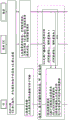
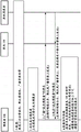
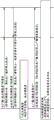
FIG. 2 shows an exemplary block diagram of an advanced V2X service;
FIG. 3 shows an exemplary single symbol resource structure on a sidelink;
FIG. 4 shows exemplary two-symbol and four-symbol resource structures on the sidelink;
FIG. 5 shows an exemplary two-symbol micro-slot resource structure on the sidelink;
FIGS. 6A and 6B show an exemplary call flow for resource reconfiguration when joining a fleet of vehicles;
FIGS. 7A and 7B show an exemplary call flow for resource reconfiguration when leaving a fleet of vehicles;
FIGS. 8A and 8B show an exemplary call flow for resource reconfiguration when switching RSUs;
FIGS. 9A and 9B show an exemplary call flow for assisted resource sensing;
FIGS. 10A and 10B show an exemplary call flow for local scheduling by a leader;
FIG. 11 illustrates the allocation or scheduled broadcast, multicast and unicast resources within a sidelink operating frequency band or sidelink resource pool;
FIG. 12 depicts an example of aggregated slot scheduling on the sidelink, where broadcast transmissions on the PSSCH span the slot boundary between slot SL1 and slot SL 2;
FIG. 13 illustrates an example of sidelink channel state information (SL-CSI) acquisition;
FIG. 14 illustrates micro-slot based scheduling;
FIG. 15A illustrates receiving a UE-initiated unicast;
FIG. 15B illustrates sending a UE-initiated unicast;
FIG. 16 illustrates an exemplary sensing method for periodic and aperiodic data transmission through a shared resource pool;
figure 17 shows an example of UE initiated scheduler selection with network control;
FIG. 18 shows an example of network initiated dispatcher selection with network control;
FIGS. 19A and 19B show an example of dispatcher elections without network control;
FIGS. 20A and 20B show an exemplary call flow for dispatcher election without network control;
FIG. 21 shows an exemplary call flow for dispatcher modification with network control;
FIG. 22 shows an example of dispatcher modification without network control;
FIG. 23 shows an exemplary call flow for dispatcher modification without network control;
FIGS. 24A and 24B show an exemplary call flow for resource allocation mode switching with network control;
FIGS. 25A and 25B show an exemplary call flow for resource allocation mode switching without network control;
26A, 26B, and 26C illustrate examples of sensing-based resource selection;
FIG. 27 shows an example of a call flow based on sensed resource selection;
fig. 28 shows an example of congestion measurement; and
fig. 29 shows an example of a call flow of transmission based on congestion control.
Detailed Description
Exemplary communication System and network
The third generation partnership project (3GPP) developed technical standards for cellular telecommunications network technology including radio access, core transport network and service capabilities-including work on codecs, security and quality of service. Recent Radio Access Technology (RAT) standards include WCDMA (commonly referred to as 3G), LTE (commonly referred to as 4G), LTE-Advanced standards, and New Radio (NR) also referred to as "5G". The 3GPP NR standard development is expected to continue and includes the definition of the next generation radio access technology (new RAT), which is expected to include the provision of new flexible radio access below 7GHz and new ultra mobile broadband radio access above 7 GHz. Flexible radio access is expected to consist of new non-backwards compatible radio access in a new spectrum below 7GHz, and is expected to include different modes of operation that can be multiplexed together in the same spectrum to address a wide set of 3GPP NR use cases with different requirements. It is expected that ultra mobile broadband includes cmWave and mmWave spectrum, which will provide opportunities for ultra mobile broadband access for e.g. indoor applications and hotspots. In particular, with cmWave and mmWave specific design optimizations, it is expected that ultra mobile broadband will share a common design framework with flexible radio access below 7 GHz.
The 3GPP has determined various use cases that NR support is expected to yield a wide variety of user experience requirements for data rate, latency and mobility. Use cases include the following general categories: enhanced mobile broadband (eMBB) ultra-reliable low-latency communications (URLLC), large-scale machine type communications (mtc), network operations (e.g., network slicing, routing, migration and interworking, energy conservation), and enhanced vehicle-to-everything (eV2X) communications, which may include any of vehicle-to-vehicle communications (V2V), vehicle-to-infrastructure communications (V2I), vehicle-to-network communications (V2N), vehicle-to-pedestrian communications (V2P), and vehicle-to-other entity communications. Specific services and applications in these categories include, for example, surveillance and sensor networks, device remote control, two-way remote control, personal cloud computing, video streaming, wireless cloud office, first responder connection, automobile emergency calls, disaster alerts, real-time gaming, multi-player video calls, autonomous driving, augmented reality, haptic internet, virtual reality, home automation, robotics, and aerial drones, to name a few. All of these and other use cases are contemplated herein.
Fig. 1A illustrates an exemplary communication system 100 in which the systems, methods, and devices described and claimed herein may be used. The communication system 100 may include wireless transmit/receive units (WTRUs) 102a, 102b, 102c, 102d, 102e, 102f, and/or 102g (which may be referred to generally or collectively as WTRUs 102). The communication system 100 may include a Radio Access Network (RAN)103/104/105/103b/104b/105b, a core network 106/107/109, a Public Switched Telephone Network (PSTN)108, the internet 110, other networks 112, and network services 113. The network services 113 may include, for example, V2X servers, V2X functions, ProSe servers, ProSe functions, IoT services, video streaming, and/or edge computing, among others.
It is to be appreciated that the concepts disclosed herein may be utilized with any number of WTRUs, base stations, networks, and/or network elements. Each WTRU 102 may be any type of device or apparatus configured to operate and/or communicate in a wireless environment. In the example of fig. 1A, each WTRU 102 is depicted in fig. 1A-1E as a handheld wireless communication device. It should be appreciated that in various use cases contemplated with respect to wireless communications, each WTRU may include or be included in any type of device or apparatus configured to transmit and/or receive wireless signals including, by way of example only, a User Equipment (UE), a mobile station, a fixed or mobile subscriber unit, a pager, a cellular telephone, a Personal Digital Assistant (PDA), a smartphone, a laptop, a tablet, a netbook, a notebook computer, a personal computer, a wireless sensor, consumer electronics, a wearable device such as a smart watch or smart garment, a medical or electronic health device, a robot, industrial equipment, a drone, a vehicle such as an automobile, bus or truck, train or airplane, and the like.
The TRPs 119a, 119b may be any type of device configured to wirelessly interface with at least one of the WTRUs 102d to facilitate access to one or more communication networks, such as the core network 106/107/109, the internet 110, network services 113, and/or other networks 112. The RSUs 120a and 120b may be any type of device configured to wirelessly interface with at least one of the WTRUs 102e or 102f to facilitate access to one or more communication networks, such as the core network 106/107/109, the internet 110, the other networks 112, and/or the network services 113. For example, the base stations 114a, 114B may be Base Transceiver Stations (BTSs), Node-Bs, eNode Bs, Home Node Bs, Home eNode Bs, next generation Node-Bs (gnode Bs), satellites, site controllers, Access Points (APs), wireless routers, and the like.
The base station 114a may be part of the RAN 103/104/105, and the RAN 103/104/105 may also include other base stations and/or network elements (not shown), such as Base Station Controllers (BSCs), Radio Network Controllers (RNCs), relay nodes, and so forth. Similarly, base station 114b may be part of RAN 103b/104b/105b, and RAN 103b/104b/105b may also include other base stations and/or network elements (not shown), such as BSCs, RNCs, relay nodes, and so forth. The base station 114a may be configured to transmit and/or receive wireless signals within a particular geographic area, which may be referred to as a cell (not shown). Similarly, base station 114b may be configured to transmit and/or receive wired and/or wireless signals within a particular geographic area, which may be referred to as a cell (not shown). The cell may be further divided into cell sectors. For example, the cell associated with base station 114a may be divided into 3 sectors. Thus, for example, the base station 114a may include 3 transceivers, e.g., one transceiver per sector of a cell. The base station 114a may employ multiple-input multiple-output (MIMO) techniques, and thus may use multiple transceivers, e.g., for each sector of a cell.
The base station 114a may communicate with one or more of the WTRUs 102a, 102b, 102c, and 102g over an air interface 115/116/117, and the air interface 115/116/117 may be any suitable wireless communication link (e.g., Radio Frequency (RF), microwave, Infrared (IR), Ultraviolet (UV), visible, cmWave, mmWave, etc.). The air interface 115/116/117 may be established using any suitable Radio Access Technology (RAT).
The RRHs 118a, 118b, TRPs 119a, 119b and/or RSUs 120a, 120b may communicate with one or more of the WTRUs 102c, 102d, 102e, 102f over the air interfaces 115c/116c/117c, which air interfaces 115c/116c/117c may be any suitable wireless communication links (e.g., RF, microwave, IR, ultraviolet UV, visible, cmWave, mmWave, etc.). Air interfaces 115c/116c/117c may be established using any suitable RAT.
The base station 114a in the RAN 103/104/105 and the WTRUs 102a, 102b, 102c, and 102g, or the RRHs 118a and 118b, TRPs 119a and 119b, and/or the RSUs 120a and 120b in the RAN 103b/104b/105b and the WTRUs 102c, 102d may implement a radio technology such as evolved UMTS terrestrial radio Access (E-UTRA), which may establish the air interface 115/116/117 or 115c/116c/117c, respectively, using, for example, Long Term Evolution (LTE) and/or LTE-Advanced (LTE-A). Air interfaces 115/116/117 or 115c/116c/117c may implement 3GPP NR techniques. LTE and LTE-a technologies may include LTE D2D and/or V2X technologies and interfaces (such as sidelink communications, etc.). Similarly, 3GPP NR technology may include NR V2X technology and interfaces (such as sidelink communications, etc.).
The base station 114a in the RAN 103/104/105 and the WTRUs 102a, 102b, 102c, and 102g, or the RRHs 118a and 118b, TRPs 119a and 119b, and/or RSUs 120a and 120b in the RAN 103b/104b/105b and the WTRUs 102c, 102d, 102e, and 102f may implement radio technologies such as IEEE 802.16 (e.g., Worldwide Interoperability for Microwave Access (WiMAX)), CDMA2000, CDMA 20001X, CDMA2000 EV-DO, interim standard 2000(IS-2000), interim standard 95(IS-95), interim standard 856(IS-856), Global System for Mobile communications (GSM), enhanced data rates for GSM evolution (EDGE), GSM EDGE (GERAN).
The base station 114c in fig. 1A may be, for example, a wireless router, Home Node B, Home eNode B, or access point, and may utilize any suitable RAT to facilitate wireless connectivity in a local area (e.g., a business, Home, vehicle, train, air, satellite, factory, campus, etc.). The base station 114c and the WTRU 102 (e.g., WTRU 102e) may implement a radio technology such as IEEE 802.11 to establish a Wireless Local Area Network (WLAN). Similarly, the base station 114c and the WTRU 102 (e.g., WTRU 102d) may implement a radio technology such as IEEE 802.15 to establish a Wireless Personal Area Network (WPAN). The base station 114c and the WTRU 102 (e.g., WTRU 102e) may establish a pico cell or a femto cell using a cellular-based RAT (e.g., WCDMA, CDMA2000, GSM, LTE-A, NR, etc.). As shown in fig. 1A, the base station 114c may be directly connected to the internet 110. Thus, the base station 114c may not be required to access the internet 110 via the core network 106/107/109.
The RAN 103/104/105 and/or the RANs 103b/104b/105b may be in communication with a core network 106/107/109, and the core network 106/107/109 may be any type of network configured to provide voice, data, messaging, authorization and authentication, applications, and/or voice over internet protocol (VoIP) services to one or more of the WTRUs 102. For example, the core network 106/107/109 may provide call control, billing services, mobile location-based services, prepaid calls, internet connectivity, packet data network connectivity, ethernet connectivity, video distribution, etc., and/or perform high-level security functions such as user authentication.
Although not illustrated in fig. 1A, it is to be appreciated that the RAN 103/104/105 and/or the RANs 103b/104b/105b and/or the core network 106/107/109 may communicate directly or indirectly with other RANs that employ the same RAT as the RAN 103/104/105 and/or the RANs 103b/104b/105b or a different RAT. For example, in addition to connecting to RAN 103/104/105 and/or RAN 103b/104b/105b, which may utilize E-UTRA radio technology, core network 106/107/109 may also communicate with other RANs (not shown) that employ GSM or NR radio technologies.
The core network 106/107/109 may also serve as a gateway for the WTRU 102 to access the PSTN 108, the internet 110, and/or other networks 112. The PSTN 108 may include a circuit-switched telephone network that provides Plain Old Telephone Service (POTS). The internet 110 may include a global system of interconnected computer networks and devices that utilize common communication protocols, such as the Transmission Control Protocol (TCP), User Datagram Protocol (UDP), and Internet Protocol (IP) in the TCP/IP internet protocol suite. Other networks 112 may include wired or wireless communication networks owned and/or operated by other service providers. For example, the network 112 may include any type of packet data network (e.g., an IEEE 802.3 ethernet network) or another core network connected to one or more RANs, which may employ the same RAT as the RAN 103/104/105 and/or the RANs 103b/104b/105b, or a different RAT.
Some or all of the WTRUs 102a, 102b, 102c, 102d, 102e, and 102f in the communication system 100 may include multi-mode capabilities, e.g., the WTRUs 102a, 102b, 102c, 102d, 102e, and 102f may include multiple transceivers that communicate with different wireless networks over different wireless links. For example, the WTRU 102g shown in figure 1A may be configured to communicate with a base station 114a, which may employ a cellular-based radio technology, and with a base station 114c, which may employ an IEEE 802 radio technology.
Although not illustrated in fig. 1A, it is to be appreciated that the user device may establish a wired connection to the gateway. The network may be a Residential Gateway (RG). The RG may provide connectivity to a core network 106/107/109. It is to be appreciated that many of the concepts contained herein may be equally applied to UEs that are WTRUs and UEs that use wired connections to connect to a network. For example, the concepts applied to wireless interfaces 115, 116, 117 and 115c/116c/117c may be equally applied to wired connections.
Fig. 1B is a system diagram illustrating RAN 103 and core network 106. As described above, the RAN 103 may employ UTRA radio technology to communicate with the WTRUs 102a, 102b, and 102c over the air interface 115. RAN 103 may also communicate with core network 106. As shown in fig. 1B, the RAN 103 may include Node- bs 140a, 140B, and 140c, and each of the Node- bs 140a, 140B, and 140c may include one or more transceivers for communicating with the WTRUs 102a, 102B, and 102c over the air interface 115. The Node- bs 140a, 140B, and 140c may each be associated with a particular cell (not shown) within the RAN 103. The RAN 103 may also include RNCs 142a, 142 b. It is to be appreciated that the RAN 103 can include any number of Node-Bs and Radio Network Controllers (RNCs).
As shown in FIG. 1B, the Node-Bs 140a, 140B may communicate with the RNC 142 a. In addition, Node-B140 c may communicate with RNC 142B. The Node- bs 140a, 140B and 140c may communicate with the respective RNCs 142a and 142B via the Iub interface. RNCs 142a and 142b may communicate with each other via an Iur interface. Each RNC 142a and 142B may be configured to control the respective Node-B140 a, 140B and 140c to which it is connected. In addition, each RNC 142a and 142b may be configured to perform or support other functions such as outer loop power control, load control, admission control, packet scheduling, handoff control, macro diversity, security functions, data encryption, and the like.
The core network 106 shown in fig. 1B may include a Media Gateway (MGW)144, a Mobile Switching Center (MSC)146, a Serving GPRS Support Node (SGSN)148, and/or a Gateway GPRS Support Node (GGSN) 150. Although each of the above elements are described as part of the core network 106, it is to be appreciated that any of these elements may be owned and/or operated by an entity other than the core network operator.
The RNC 142a in the RAN 103 may also be connected to the SGSN 148 in the core network 106 over an IuPS interface. The SGSN 148 may be coupled to a GGSN 150. The SGSN 148 and GGSN 150 may provide the WTRUs 102a, 102b, and 102c with access to packet-switched networks, such as the internet 110, to facilitate communications between the WTRUs 102a, 102b, and 102c and IP-enabled devices.
The core network 106 may also be connected to other networks 112, and the other networks 112 may include other wired or wireless networks owned and/or operated by other service providers.
Fig. 1C is a system diagram illustrating RAN104 and core network 107. As described above, the RAN104 may employ E-UTRA radio technology to communicate with the WTRUs 102a, 102b, and 102c over the air interface 116. RAN104 may also communicate with a core network 107.
RAN104 may include eNode- bs 160a, 160B, and 160c, although it is appreciated that RAN104 may include any number of eNode-bs. The eNode- bs 160a, 160B and 160c may each include one or more transceivers for communicating with the WTRUs 102a, 102B and 102c over the air interface 116. For example, eNode- bs 160a, 160B, and 160c may implement MIMO technology. Thus, for example, eNode-B160a may use multiple antennas to transmit wireless signals to WTRU 102a and to receive wireless signals from WTRU 102 a.
Each eNode-B160a, 160B, and 160c can be associated with a particular cell (not shown), can be configured to handle radio resource management decisions, handover decisions, scheduling of users in the uplink and/or downlink, and the like. As shown in fig. 1C, eNode-bs 160a, 160B, and 160C can communicate with each other over an X2 interface.
The core network 107 shown in fig. 1C may include a mobility management gateway (MME)162, a serving gateway 164, and a Packet Data Network (PDN) gateway 166. Although each of the above elements are described as part of the core network 107, it is to be appreciated that any of these elements may be owned and/or operated by an entity other than the core network operator.
Serving gateway 164 may be connected to each of eNode- bs 160a, 160B, and 160c in RAN104 via an S1 interface. The serving gateway 164 may generally route and forward user data packets to and from the WTRUs 102a, 102b, and 102 c. The serving gateway 164 may also perform other functions such as anchoring the user plane during inter-eNode B handovers, triggering paging when downlink data is available to the WTRUs 102a, 102B, and 102c, managing and storing the context of the WTRUs 102a, 102B, and 102c, and the like.
The serving gateway 164 may also be connected to a PDN gateway 166, which the PDN gateway 166 may provide the WTRUs 102a, 102b, and 102c with access to a packet-switched network, such as the internet 110, to facilitate communications between the WTRUs 102a, 102b, and 102c and IP-enabled devices.
The core network 107 may facilitate communication with other networks. For example, the core network 107 may provide the WTRUs 102a, 102b, and 102c with access to a line-switched network, such as the PSTN 108, to facilitate communications between the WTRUs 102a, 102b, and 102c and conventional landline communication devices. For example, the core network 107 may include or may communicate with an IP gateway (e.g., an IP Multimedia Subsystem (IMS) server) that serves as an interface between the core network 107 and the PSTN 108. In addition, the core network 107 may provide the WTRUs 102a, 102b, and 102c with access to the network 112, which network 112 may include other wired or wireless networks owned and/or operated by other service providers.
Fig. 1D is a system diagram illustrating RAN105 and core network 109. The RAN105 may employ NR radio technology to communicate with the WTRUs 102a and 102b over the air interface 117. RAN105 may also communicate with core network 109. A non-3 GPP interworking function (N3IWF)199 may employ non-3 GPP radio technology to communicate with the WTRU 102c over the air interface 198. The N3IWF 199 may also communicate with the core network 109.
RAN105 may include enode-bs 180a and 180B. It is to be appreciated that RAN105 may include any number of enode-bs. Each of the enode-bs 180a and 180B may include one or more transceivers for communicating with the WTRUs 102a and 102B over the air interface 117. When integrated access and backhaul connections are used, the same air interface may be used between the WTRU and the enode-B, which may be the core network 109 via one or more gnbs. The gNode-Bs 180a and 180B may implement MIMO, MU-MIMO, and/or digital beamforming techniques. Thus, for example, the enode-B180 a may transmit and receive wireless signals to and from the WTRU 102a using multiple antennas. It should be appreciated that RAN105 may employ other types of base stations, such as eNode-bs. It is also to be appreciated that RAN105 may employ more than one type of base station. For example, the RAN may employ eNode-B and gNode-B.
The N3IWF 199 may include a non-3 GPP access point 180 c. It is to be appreciated that the N3IWF 199 may include any number of non-3 GPP access points. Non-3 GPP access point 180c may include one or more transceivers for communicating with WTRU 102c over air interface 198. Non-3 GPP access point 180c may communicate with WTRU 102c over air interface 198 using 802.11 protocols.
The enode-bs 180a and 180B may each be associated with a particular cell (not shown) and may be configured to handle radio resource management decisions, handover decisions, scheduling of users in the uplink and/or downlink, and so on. As shown in FIG. 1D, the gNode-Bs 180a and 180B may communicate with each other over, for example, an Xn interface.
The core network 109 shown in fig. 1D may be a 5G core network (5 GC). The core network 109 may provide numerous communication services to clients interconnected by radio access networks. The core network 109 includes a plurality of entities that perform the functions of the core network. The term "core network entity" or "network function" as used herein refers to any entity that performs one or more functions of the core network. It should be appreciated that such core network entities may be logical entities implemented in the form of computer-executable instructions (software) stored in a memory of a device, or computer system, configured for wireless and/or network communication, such as system 90 shown in fig. 1G, and executed on a processor thereof.
In the example of fig. 1D, the 5G core network 109 may include an access and mobility management function (AMF)172, a Session Management Function (SMF)174, User Plane Functions (UPFs) 176a and 176b, a user data management function (UDM)197, an authentication server function (AUSF)190, a Network Exposure Function (NEF)196, a Policy Control Function (PCF)184, a non-3 GPP interworking function (N3IWF)199, a User Data Repository (UDR) 178. While each of the foregoing elements are described as being part of the 5G core network 109, it is to be appreciated that any of these elements may be owned and/or operated by an entity other than the core network operator. It is also appreciated that the 5G core network may not be made up of all of these elements, may be made up of additional elements, and may be made up of multiple instances of each of these elements. Fig. 1D shows the network functions directly connected to each other, however, it should be appreciated that they may communicate via a routing agent, such as a diameter routing agent, or a message bus.
In the example of fig. 1D, the connections between network functions are implemented via a set of interfaces or reference points. It is to be appreciated that a network function may be emulated, described, or implemented as a set of services that are enabled (invoke) or invoked (call) by other network functions or services. Enablement of network function services may be accomplished via a direct connection between network functions, exchange of messaging over a message bus, invoking a software function, and so forth.
The AMF 172 may be connected to the RAN105 via an N2 interface and may serve as a control node. For example, the AMF 172 may be responsible for registration management, connection management, reachability management, access authentication, access authorization. The AMF may be responsible for forwarding user plane tunnel configuration information to the RAN105 via the N2 interface. The AMF 172 may receive user plane tunnel configuration information from the SMF via an N11 interface. The AMF 172 may generally route and forward NAS packets to and from the WTRUs 102a, 102b, and 102c via an N1 interface. The N1 interface is not shown in fig. 1D.
The SMF 174 may be connected to the AMF 172 via an N11 interface. Similarly, SMFs may connect to PCF 184 via an N7 interface and to UPFs 176a and 176b via an N4 interface. SMF 174 may serve as a control node. For example, the SMF 174 may be responsible for session management, IP address assignment to the WTRUs 102a, 102b, and 102c, management and configuration of traffic steering rules in the UPF 176a and UPF 176b, and generation of downlink data notifications to the AMF 172.
The UPFs 176a and 176b may provide the WTRUs 102a, 102b, and 102c with access to a Packet Data Network (PDN), such as the internet 110, to facilitate communications between the WTRUs 102a, 102b, and 102c and other devices. UPFs 176a and 176b may also provide WTRUs 102a, 102b, and 102c with access to other types of packet data networks. For example, the other network 112 may be an ethernet network or any type of network that exchanges data packets. UPFs 176a and 176b may receive traffic steering rules from SMF 174 via an N4 interface. UPFs 176a and 176b may provide access to the packet data network by interfacing the packet data network with N6, or by interfacing with each other and other UPFs via an N9 interface. In addition to providing access to the packet data network, the UPF 176 may also be responsible for packet routing and forwarding, policy rule enforcement, quality of service processing for user plane traffic, downlink packet buffering.
The AMF 172 may also be connected to the N3IWF 199, for example, via an N2 interface. The N3IWF facilitates the connection between the WTRU 102c and the 5G core network 170, for example, via radio interface technologies not defined by 3 GPP. The AMF may interact with the N3IWF 199 in the same or similar manner as it interacts with the RAN 105.
The AUSF 190 performs authentication-related operations, connects to the UDM 178 via an N13 interface, and connects to the AMF 172 via an N12 interface.
The application function 188 may interact with network functions in the 5G core network 109. Interaction between the application function 188 and the network function may occur via a direct interface, or may occur via the NEF 196. The application function 188 may be considered part of the 5G core network 109 or may be external to the 5G core network 109 and deployed by an enterprise having a business relationship with a mobile network operator.
Network slicing is a mechanism that can be used by mobile network operators to support one or more ' virtual ' core networks behind the operators ' air interfaces. This involves 'slicing' the core network into one or more virtual networks to support different RANs, or different service types running throughout a single RAN. Network slicing enables operators to create customized networks to provide optimized solutions for different market scenarios requiring diverse requirements (e.g., requirements in terms of functionality, performance, and isolation).
The 3GPP has designed a 5G core network to support network slicing. Network slicing is a good tool that network operators can use to support a diverse set of 5G use cases (e.g., large-scale IoT, critical communications, V2X, and enhanced mobile broadband) that require very diverse and sometimes extreme requirements. Without the use of network slicing techniques, when each use case has its own specific set of performance, scalability and availability requirements, it is likely that the network architecture is not flexible and scalable enough to efficiently support the broader use case requirements. Furthermore, the introduction of new network services should be made more efficient.
Referring again to fig. 1D, in a network slice scenario, the WTRU 102a, 102b or 102c may connect to the AMF 172 via an N1 interface. The AMF may be logically part of one or more slices. The AMF may coordinate the connection or communication of the WTRU 102a, 102b, or 102c with one or more UPFs 176a and 176b, SMF 174, and other network functions. Each of UPFs 176a and 176b, SMF 174, and other network functions may be part of the same slice or different slices. When they are part of different slices, they may be isolated from each other in the sense that they may utilize different computing resources, security credentials, etc.
The core network 109 may facilitate communication with other networks. For example, the core network 109 may include, or may communicate with, an IP gateway, such as an IP Multimedia Subsystem (IMS) server, that acts as an interface between the 5G core network 109 and the PSTN 108. For example, the core network 109 may include, or communicate with, a Short Message Service (SMS) service center that facilitates communication via a short message service. For example, the 5G core network 109 may facilitate the exchange of non-IP data packets between the WTRUs 102a, 102b, 102c and the server or application function 188. In addition, the core network 170 may provide WTRUs 102a, 102b, and 102c with access to the network 112, which network 112 may include other wired or wireless networks owned and/or operated by other service providers.
The core network entities described herein and illustrated in fig. 1A, 1C, 1D and 1E are identified by names assigned to these entities in certain existing 3GPP specifications, although it is understood that these entities and functions may be identified by other names in the future, and that certain entities or functions may be combined in future specifications published by 3GPP, including future 3GPP NR specifications. Thus, the particular network entities and functions described and illustrated in fig. 1A, 1B, 1C, 1D, and 1E are provided as examples only, and it is to be understood that the subject matter disclosed and claimed herein may be embodied or carried out in any similar communication system, whether presently defined or defined in the future.
FIG. 1E illustrates an exemplary communication system 111 in which the systems, methods, and devices described herein may be used. The communication system 111 may include a wireless transmit/receive unit (WTRU) A, B, C, D, E, F, a base station gNB 121, a V2X server 124, and roadside units (RSUs) 123a and 123 b. In practice, the concepts presented herein may be applied to any number of WTRUs, base stations gNB, V2X networks, and/or other network elements. One or several or all of the WTRUs a, B, C, D, E, and F may be outside the range of the access network coverage area 131. WTRUs a, B, and C form a V2X group, where WTRU a is the group leader and WTRUs B and C are the group members.
WTRUs a, B, C, D, E, and F may communicate with each other over Uu interface 129 via the gNB 121 if they are within access network coverage 131. In the example of fig. 1E, WTRUs B and F are shown within access network coverage 131. WTRUs a, B, C, D, E, and F may communicate directly with each other, whether they are within access network coverage 131 or outside access network coverage 131, via a sidelink interface (e.g., PC5 or NR PC5), such as interfaces 125a, 125b, or 128. For example, in the example of fig. 1E, a WRTU D outside the access network coverage area 131 communicates with a WTRU F within the coverage area 131.
WTRUs a, B, C, D, E, and F may communicate with RSUs 123a or 123b via a vehicle-to-network (V2N)133 or a lateral link interface 125 b. WTRUs a, B, C, D, E, and F may communicate with a V2X server 124 via a vehicle-to-infrastructure (V2I) interface 127. WTRUs a, B, C, D, E, and F may communicate with another UE via a vehicle-to-person (V2P) interface 128.
Fig. 1F is a block diagram of an example device or apparatus WTRU 102 (such as the WTRU 102 of fig. 1A, 1B, 1C, 1D, or 1E) that may be configured for wireless communication and operation in accordance with the systems, methods, and apparatus described herein. As shown in fig. 1F, an exemplary WTRU 102 may include a processor 118, a transceiver 120, a transmit/receive element 122, a speaker/microphone 124, a keypad 126, a display/touchpad/indicator 128, non-removable memory 130, removable memory 132, a power source 134, a Global Positioning System (GPS) chipset 136, and other peripherals 138. It is to be appreciated that the WTRU 102 may include any subcombination of the above elements. In addition, base stations 114a and 114B, and/or nodes that base stations 114a and 114B may represent, such as, but not limited to, Base Transceiver Stations (BTSs), Node-Bs, site controllers, Access Points (APs), home Node-Bs, evolved home Node-Bs (eNodeBs), home evolved Node-Bs (HeNBs), home evolved Node-B gateways, next generation Node-Bs (gNodes Bs), proxy nodes, and the like, may include some or all of the elements described in FIG. 1F and described herein.
The processor 118 may be a general purpose processor, a special purpose processor, a conventional processor, a Digital Signal Processor (DSP), a plurality of microprocessors, one or more microprocessors in association with a DSP core, a controller, a microcontroller, Application Specific Integrated Circuits (ASICs), Field Programmable Gate Arrays (FPGAs) circuits, any other type of Integrated Circuit (IC), a state machine, or the like. The processor 118 may perform signal coding, data processing, power control, input/output processing, and/or any other functions that enable the WTRU 102 to operate in a wireless environment. The processor 118 may be coupled to a transceiver 120, and the transceiver 120 may be coupled to a transmit/receive element 122. Although fig. 1F depicts the processor 118 and the transceiver 120 as separate components, it is to be appreciated that the processor 118 and the transceiver 120 may be integrated together in an electronic package or chip.
The UE's transmit/receive element 122 may be configured to transmit signals to or receive signals from a base station (e.g., base station 114a of fig. 1A) over air interface 115/116/117, or to transmit signals to or receive signals from another UE over air interface 115d/116d/117 d. For example, transmit/receive element 122 may be an antenna configured to transmit and/or receive RF signals. For example, the transmit/receive element 122 may be an emitter/detector configured to transmit and/or receive IR, UV, or visible light signals. The transmit/receive element 122 may be configured to transmit and receive both RF signals and optical signals. It is to be appreciated that the transmit/receive element 122 may be configured to transmit and/or receive any combination of wireless or wired signals.
Additionally, although transmit/receive element 122 is depicted in fig. 1F as a single element, WTRU 102 may include any number of transmit/receive elements 122. More specifically, the WTRU 102 may employ MIMO technology. Thus, the WTRU 102 may include two or more transmit/receive elements 122 (e.g., multiple antennas) for transmitting and receiving wireless signals over the air interface 115/116/117.
The processor 118 of the WTRU 102 may be coupled to a speaker/microphone 124, a keypad 126, and/or a display/touchpad/indicator 128 (e.g., a Liquid Crystal Display (LCD) display unit or an Organic Light Emitting Diode (OLED) display unit) so that user input data may be received therefrom. The processor 118 may also output user data to a speaker/microphone 124, a keypad 126, and/or a display/touchpad/indicator 128. In addition, the processor 118 may access information from, and store data in, any type of suitable memory, such as non-removable memory 130 and/or removable memory 132. The non-removable memory 130 may include Random Access Memory (RAM), Read Only Memory (ROM), a hard disk, or any other type of memory storage device. The removable memory 132 may include a Subscriber Identity Module (SIM) card, a memory stick, a Secure Digital (SD) memory card, and the like. The processor 118 may access information from, and store data in, a memory that is not physically located in the WTRU 102, such as a memory hosted on a server in the cloud or in an edge computing platform, or in a home computer (not shown).
The processor 118 may receive power from the power source 134 and may be configured to distribute power to other components in the WTRU 102 and/or control power to other components in the WTRU 102. The power source 134 may be any suitable device for powering the WTRU 102. For example, the power source 134 may include one or more dry cell batteries, solar cells, fuel cells, or the like.
The processor 118 may also be coupled to a GPS chipset 136, which the GPS chipset 136 may be configured to provide location information (e.g., longitude and latitude) regarding the current location of the WTRU 102. In addition to or instead of the information from the GPS chipset 136, the WTRU 102 may receive location information from base stations (e.g., base stations 114a, 114b) over the air interface 115/116/117 and/or determine its location based on the timing of the reception of signals from two or more nearby base stations. It is to be appreciated that the WTRU 102 may acquire location information using any suitable location determination method.
The processor 118 may be further coupled to other peripherals 138, which peripherals 138 may include one or more software and/or hardware modules that provide additional features, functionality, and/or a wired or wireless connection. For example, peripheral devices 138 may include various sensors such as accelerometers, biometric (e.g., fingerprint) sensors, electronic compasses, satellite transceivers, digital cameras (for photo or video), Universal Serial Bus (USB) ports or other interconnection interfaces, vibration devices, television transceivers, hands-free headsets, portable devices, and the like, A module, a Frequency Modulation (FM) radio unit, a digital music player, a media player, a video game player module, an internet browser, etc.
The WTRU 102 may be included in other devices or apparatuses, such as sensors, consumer electronics, wearable apparatuses such as smart watches or smart clothing, medical or electronic health apparatuses, robots, industrial equipment, drones, vehicles such as cars, trucks, trains, or airplanes. The WTRU 102 may connect to other components, modules, or systems of such devices or apparatuses via one or more interconnect interfaces, such as an interconnect interface that may include one of the peripherals 138.
Fig. 1G is a block diagram of an exemplary computer system 90 in which one or more devices of the communication networks shown in fig. 1A, 1C, 1D, and 1E may be embodied, such as certain nodes or functional entities in RAN 103/104/105, core network 106/107/109, PSTN 108, internet 110, other networks 112, or network services 113. The computing system 90 may comprise a computer or server and may be controlled primarily by computer readable instructions, which may take the form of software, where or in any way store or access such software. Such computer readable instructions may be executed within processor 91 to cause computing system 90 to operate. The processor 91 may be a general-purpose processor, a special purpose processor, a conventional processor, a Digital Signal Processor (DSP), a plurality of microprocessors, one or more microprocessors in association with a DSP core, a controller, a microcontroller, Application Specific Integrated Circuits (ASICs), Field Programmable Gate Arrays (FPGAs) circuits, any other type of Integrated Circuit (IC), a state machine, or the like. The processor 91 may perform signal coding, data processing, power control, input/output processing, and/or any other functions that enable the computing system 90 to operate in a communication network. Coprocessor 81 is an optional processor other than main processor 91 that may perform additional functions or assist processor 91. Processor 91 and/or coprocessor 81 may receive, generate, and process data associated with the methods and apparatus disclosed herein.
In operation, processor 91 retrieves, decodes, and executes instructions and transfers information to and from other resources via the computing system's primary data transfer path, system bus 80. Such a system bus connects components in the computing system 90 and defines a medium for data exchange. System bus 80 typically includes data lines for transmitting data, address lines for transmitting addresses, and control lines for transmitting interrupts and for manipulating the system bus. An example of such a system bus 80 is a PCI (peripheral component interconnect) bus.
The memory coupled to system bus 80 includes Random Access Memory (RAM)82 and Read Only Memory (ROM) 93. Such memories include circuitry that allows information to be stored and retrieved. The ROM 93 typically contains stored data that cannot be easily changed. The data stored in the RAM 82 may be read or changed by the processor 91 or other hardware devices. Access to the RAM 82 and/or ROM 93 may be controlled by a memory controller 92. Memory controller 92 may provide address translation functionality to translate virtual addresses to physical addresses when instructions are executed. The memory controller 92 may also provide memory protection functions that isolate processes within the system and isolate system processes from user processes. Thus, a program running in the first mode can only access memory mapped by the virtual address space of its own process; it cannot access memory within the virtual address space of other processes unless memory sharing between processes is set.
In addition, the computing system 90 may include a peripheral controller 83 responsible for communicating instructions from the processor 91 to peripheral devices, such as a printer 94, a keyboard 84, a mouse 95, and a disk drive 85.
The display 86, controlled by a display controller 96, is used to display visual output generated by the computing system 90. Such visual output may include text, graphics, animated graphics, and video. The visual output may be provided in the form of a Graphical User Interface (GUI). The display 86 may be implemented using a CRT based video display, an LCD based flat panel display, a gas plasma based flat panel display, or a touch panel. The display controller 96 includes the electronic components necessary to generate the video signals to the display 86.
In addition, the computing system 90 may contain communication circuitry, such as a wireless or wired network adapter 97, that may be used to connect the computing system 90 to external communication networks or devices, such as the RAN 103/104/105, core network 106/107/109, PSTN 108, internet 110, WTRU 102, or other networks 112 of fig. 1A, 1B, 1C, 1D, and 1E, to enable the computing system 90 to communicate with other nodes or functional entities of these networks. The communication circuitry may be used to perform the transmitting and receiving steps of certain devices, nodes or functional entities recited herein, either alone or in combination with the processor 91.
It should be understood that any or all of the devices, systems, methods, and processes described herein may be embodied in the form of computer-executable instructions (e.g., program code) stored on a computer-readable storage medium, which when executed by a processor, such as processor 118 or 91, cause the processor to perform and/or implement the systems, methods, and processes described herein. In particular, any of the steps, operations, or functions described herein may be implemented in the form of such computer-executable instructions executed on a processor of a device or computing system configured for wireless and/or wired network communication. Computer-readable storage media include volatile and nonvolatile, removable and non-removable media implemented in any non-transitory (e.g., tangible or physical) method or technology for storage of information, although such computer-readable storage media do not include signals. Computer-readable storage media includes, but is not limited to, RAM, ROM, EEPROM, flash memory or other memory technology, CD-ROM, Digital Versatile Disks (DVD) or other optical disk storage, magnetic cassettes, magnetic tape, magnetic disk storage or other magnetic storage devices, or any other tangible or physical medium which can be used to store the desired information and which can be accessed by a computing system.
Brief introduction
In release 14 of LTE V2X, basic requirements for V2X services (e.g., support for low latency and reliable message exchange between vehicles and infrastructure to improve safety and efficiency) have been supported for road safety services to improve system level performance at high density while meeting vehicle-to-vehicle (V2V) latency requirements. Two configurations of resource pools are specified for scheduling assignments on the Physical side uplink control channel (PSCCH) and associated data transmissions on the Physical side uplink shared channel (PSCCH) (see 3GPP TS36.213 Physical layer procedures, Release 15, V15.2.0).
For V2X communication, sidelink transmission modes 3 and 4 are specified in TS36.213 in order to meet latency requirements and to accommodate high doppler spread and high density of vehicles.
Mode 3, on the other hand, uses a centralized eNB scheduler. The vehicular UE and eNB use the Uu interface to schedule communications on the sidelink (e.g., PC5 interface).
As shown in fig. 2, advanced V2X applications have shifted to more aggressive and intelligent transportation infrastructures and made the anticipated requirements more stringent to meet the required data rates, latency, reliability, system capacity, service coverage, etc. Current LTE V2X solutions do not provide the required latency and reliability, and the required data rate. Thus, how to optimize the resource structure and how to allocate resources to support the advanced V2X service is an important issue that needs to be handled and solved.
Methods and systems for resource management on a sidelink of a vehicle to everything (V2X) scenario are disclosed.
Methods and systems for resource structures on sidelink are disclosed. The control channel and the data channel are frequency division multiplexed (FDMed) or time division multiplexed (TDMed) using Orthogonal Frequency Division Multiplexed (OFDM) waveforms. Also disclosed is a time symbol-or micro-slot-based resource pool.
Methods and systems for resource configuration on a sidelink are disclosed. The resource configuration may be in a V2X system, by means of System Information (SI) or Radio Resource Control (RRC) messages over the Uu interface, or sidelink SI (SL-SI) or sidelink RRC (SL-RRC) static configuration over the PC5 interface, for example: configuration according to the automation level of the vehicle UE, configuration according to the role of the vehicle UE in the group, configuration according to the service or application and associated priority, and configuration according to the data traffic characteristics. The resource configuration may be configured locally by means of SL-SI or SL-RRC messages over the PC5 interface, for example: configuration by a specific UE, such as a group leader, roadside unit (RSU), or scheduling UE.
Methods and systems for secondary resource allocation are disclosed. The auxiliary sensing may be performed by a group leader or RSU or UE. Local scheduling may be performed by group leader or RSU or UE.
Methods and systems for dispatcher selection or election and modification of schemes both under network control and not under network control are disclosed.
Methods and systems for resource allocation mode switching schemes both under network control and not under network control are disclosed.
Methods and systems for a slot or subframe structure with control and data channel resource allocations for different communications are disclosed. Both slot-based and micro-slot-based are proposed.
Methods and systems for sensing schemes for both periodic and aperiodic data transmission are disclosed. Sensing is performed using an adjustable sensing window, and candidate resources are selected based on the sensing results. Channel sensing, such as Listen Before Talk (LBT), is performed prior to transmission on the selected resources to avoid possible collisions. For high priority short latency data transmission, preemption is proposed to cover (override) the reserved resources.
Methods and systems for sensing-based resource selection schemes are disclosed. The resource selection is based on priority, latency, range, and/or congestion.
Methods and systems for a congestion control based transmission scheme are disclosed. Transmission abandonment is based on priority, latency, range, and/or congestion.
Note that: the terms "UE" and "vehicular UE" are interchangeable in this disclosure.
An example method may include receiving a configuration associated with at least one of a resource and a resource pool, wherein the resource and resource pool are located in a sidelink bandwidth portion; determining resource usage and one or more available resources in a resource pool; receiving an indication from an upper layer that a data packet is ready for transmission; selecting and reserving one or more resources in a resource pool for one or more transmissions; and transmitting one or more transmissions of the data packet based on the selected one or more resources.
Determining resource usage and one or more available resources in the resource pool may include setting a time interval of a sensing window, wherein the time interval of the sensing window is set based on at least one of: periodic or aperiodic transmission; the latency requirement of the data packet; repetition for transmitting data packets; and retransmission of the data packet in accordance with hybrid automatic repeat request (HARQ) feedback.
Determining resource usage and one or more available resources in the resource pool may include at least one of: sensing resource usage by decoding Sidelink Control Information (SCI) regarding scheduled or reserved or preempted resources; measuring at least one of a side link reference signal received power (SL-RSRP), a side link received signal strength indication (SL-RSSI), a channel busy rate, or a channel occupancy; and determining available resources based on: a determination that at least one of non-scheduled, unreserved, and non-preempted resources, resources within a communication range region, or SL-RSRP measurements of resources or SL-RSSI measurements of resources is below a threshold.
Selecting and reserving one or more resources of the resource pool may include determining a time interval for resource selection, wherein the time interval for resource selection is determined based on at least one of: one or more of a priority, latency, or reliability of the data packet to be transmitted; and one or more of repeating or retransmitting per HARQ feedback.
Selecting and reserving one or more resources in the resource pool may include selecting one or more candidate resources by comparing the measured SL-RSRP or RS-RSSI to a threshold, wherein the threshold is based on at least one of a priority, a latency, a communication range, a QoS requirement of the data packet to be transmitted, or an interference measurement or a congestion measurement of available resources.
Selecting and reserving one or more resources in the resource pool may include at least one of: selecting one or more resources based on at least one of a priority, a latency, a reliability or a communication range of a data packet to be transmitted, or a measure of interference or congestion; and selecting one or more resources for at least one of scheduling or reserving SCI, initial transmission, repetition, HARQ feedback, retransmission per HARQ feedback, or next data packet of a periodic traffic.
Sending one or more transmissions of the data packet may include: determining whether a congestion threshold has been exceeded based on at least one of a level of congestion or a priority, latency, reliability, or range of data packets to be transmitted; based on determining that the congestion threshold is not exceeded: sending one or more transmissions of the data packet; and based on determining that the congestion threshold has been exceeded, at least one of: abandoning the transmission based at least on at least one of a congestion level or a priority, latency, reliability, or range of data packets to be transmitted; or adjusting a modulation and coding scheme or a transmit power level based on at least one of a congestion level or a priority, a latency, a reliability, or a range of data packets to be transmitted; and transmitting at least one of an initial transmission, a repetition, or a retransmission of the data packet.
Resource structure
To support advanced V2X services and use cases, data communication over the sidelink is no longer limited to small periodic transmissions. To support both small and large data, which may be periodic or aperiodic (e.g., event triggered), a more scalable and flexible resource structure may be needed. Employing a multi-carrier OFDM waveform for 5G uplink transmission enables a more flexible resource structure with OFDM-based sidelink multiplexing. For example, the new radio physical side downlink control channel (NR-PSCCH) used for scheduling assignments may be time division multiplexed (TDMed) or frequency division multiplexed (FDMed) with the new radio physical side downlink control channel (NR-PSCCH) used for data transmission.
For highly autonomous vehicles, it is critical to support much higher reliability, shorter latency, and higher vehicle density. This requires an optimized resource structure to reduce latency, improve reliability and minimize congestion. As the operating bandwidth at the high frequency spectrum increases, time resources may be allocated at a finer granularity (e.g., in symbols or minislots) using different sets of parameters (e.g., 15KHz, 30KHz, 60KHz, 120KHz, and 240KHz subcarrier spacing). This may help to reduce latency and congestion, as well as improve reliability (e.g., available time resources for repetition).
For multi-carrier OFDM, the sidelink resources may be structured differently to meet the requirements for latency, reliability, data rate, coverage, etc.
As shown in fig. 3, resources on the sidelink may be formed as short as one symbol in a time domain (e.g., a symbol pool), and as many Resource Blocks (RBs) or Resource Block Groups (RBGs) (e.g., a group of contiguous RBs) or subchannels (e.g., a group of contiguous RBs or RBGs) available in a frequency direction (e.g., an RB pool or an RBG pool or a subchannel pool). This allows for very low latency transmission of messages either periodically or aperiodically (e.g., event triggered transmission), where short control signaling over the NR-RSCCH, e.g., Sidelink Control Information (SCI) as shown in the figure, and data on the new radio physical sidelink shared channel (NR-pscch) are frequency division multiplexed on the same symbol.
Since each vehicle UE may be transmitting very short, more time resources are available for other vehicle UEs in each time slot, sub-frame or frame, which improves coverage at high density areas such as intersections, multi-lane highways or overpasses, etc.
Since each vehicular UE may be transmitting in a short time, more time resources are available for transmitting repetitions to the receiver in each slot, subframe, or frame, which improves reliability with very short latency.
Since each vehicle UE may be transmitting in a short time, more time resources are available for the vehicle UE to scan its beams to different receivers for area coverage in each slot, subframe, or frame, which enables beam-based operation in the very high frequency spectrum up to 52.6 GHz.
For example, UE-v1 sends short control signaling (e.g., SCI) on NR-PSCCH on symbol 1 "Sym 1" of subframes "SF 0" and "SF l 1", respectively, with a Period "Period-v 1" from RB k1 to RB k2 or RBG k1 to RBG k2 or subchannel k1 to subchannel k2 (if more RBs are used in its bandwidth part (BWP) "BWP-v 1").
In another example, the UE-v2 sends a short message in which the control (e.g., SCI) on the NR-PSCCH and the data on the NR-PSSCH are frequency division multiplexed on the same symbol (e.g., symbol 4 "Sym 4") and the same transmission is repeated with a period "period-v 2" on symbols 5 and 6 of subframes "SF 0" and "SF l 2", respectively. The transmissions may be sent to the same receiver (e.g., for repetition of reliability) or each time to a different receiver (e.g., for beam scanning of the area coverage). Since, as shown in fig. 3, the UE-v2 transmits control on the frequency division multiplexed NR-PSCCH and data on the NR-PSCCH on one symbol, its BWP "BWP-v 2" is much larger than that of UE-v1, e.g., in the range BR 0-RB N or RBG 0-RBG N or sub-channel 0-N (if more RBs are used in its BWP "BWP-v 2"), as shown in fig. 3.
When the NR-PSCCH and the NR-PSCCH are frequency division multiplexed on the same symbol, the PSCCH carrying the SCI may be allocated at different positions in the frequency direction, for example, at the lowest or highest index of an RB, RBG, or subchannel, or at the middle of a frequency band, for example, a bandwidth part (BWP) on a sidelink, as shown in fig. 3.
As further shown in fig. 3, the NR-PSCCH carrying SCI is allocated consecutive RBs, RBGs, or sub-channels. However, the NR-PSCCH may also be distributed throughout the sidelink BWP of the vehicle UE, e.g., allocated with non-contiguous RBs, RBGs, or sub-channels, in view of frequency diversity gain.
As shown in fig. 4, resources on the sidelink may be made up of more than one symbol in the time direction (e.g., a symbol pool) and a number of RBs, RBGs, or subchannels (e.g., an RB pool, an RBG pool, or a subchannel pool) available in the frequency direction. This allows for very low latency transmission of medium or large messages periodically or aperiodically.
In one example, the UE-v1 sends short messages from RB k1 to RB k2 or RBG k1 to RBG k2 or subchannel k1 to subchannel k2 (if more RBs are used in its BWP "BWP-v 1") with a periodicity "Period-v 1", respectively, where control (e.g., SCI) on NR-PSCCH is on symbol 1 "Sym 1" of subframes "SF 0" and "SF l 1", and data on NR-PSSCH is at symbol 2 "Sym 2" of subframes "SF 0" and "SF l 1". In this case, the control on the NR-PSCCH and the data on the NR-PSSCH are time division multiplexed on the same RB or RBG or sub-channel.
In another example, the UE-v2 transmits large messages with a periodicity of "Period-v 2" where control (e.g., SCI) on the NR-PSCCH and data on the NR-PSSCH are frequency division multiplexed on symbol 5 "Sym 5" of subframes "SF 0" and "SF l 2", respectively, and the remaining data on the NR-PSSCH is on symbols 6 and 7 of subframes "SF 0" and "SF l 2". Since UE-v2 only sends large messages on 4 symbols, its BWP "BWP-v 2" is much larger than the BWP of UE-v1, in the range BR 0-RB N or RBG 0-RBG N or sub-channel 0-sub-channel N (if more RBs are used in its BWP "BWP-v 2"), as shown in the figure.
When the NR-PSCCH and NR-PSCCH are time division multiplexed as shown in fig. 4, the PSCCH carrying the SCI may be allocated at the same or different positions in the frequency direction. For example, it may be located in the same frequency range, e.g., within BWP-v1, or in a different frequency range, e.g., within BWP-v2, as shown in FIG. 3, or even in a different frequency location (not shown in FIG. 4) without any overlap.
As further shown in fig. 4, the NR-PSCCH is allocated contiguous RBs, RBGs, or subchannels. However, the NR-PSCCH may also be distributed over the entire BWP of the vehicular UE over the first symbol (e.g., allocated with non-contiguous RBs, RBGs, or sub-channels), or over the BWP of the vehicular UE over the first two symbols, e.g., using frequency-first mapping (e.g., filling frequency resources over the first symbol first, then frequency resources over the second symbol) or time-first mapping (e.g., filling time resources over the first RB, RBG, or sub-channel first, then time resources over the second RB, RBG, or sub-channel).
Additionally or alternatively, resources on the sidelink may be formed in time with minislots (e.g., having a duration of consecutive symbols). For a 14 symbol slot or subframe (e.g., a 15kHz set of subcarrier parameters, where each subframe contains one slot, then slots and subframes are interchangeable in the example), for example, a minislot may contain 1, 2, 4, or 7 symbols in succession. As shown in fig. 5, for the sidelink resource structure, a number of RBs or RBGs or subchannels available in a time-wise (e.g., a pool of minislots) two-symbol minislots and a frequency band (e.g., a pool of RBs, a pool of RBGs, or a pool of subchannels) are used. This allows a larger granularity in the time direction than a symbol-based allocation, but a finer granularity than a subframe-based allocation, which may save signaling bits for large data transmissions in a short time. The micro-slot based time allocation can be applied to both periodic and aperiodic (e.g., event-triggered) transmissions.
In one example, UE-v1 is at itBWP "BWP-v 1", from RB k1 to RB k2 or RBG k1 to RBG k2 or subchannel k1 to subchannelk2The short message is sent (if more RBs are used in its BWP "BWP-v 1"), with control (e.g., SCI) on the NR-PSCCH and data on the NR-PSCCH at minislot 1 of subframes "SF 0" and "SF l 1". In this case, the control on the NR-PSCCH and the data on the NR-PSSCH are time division multiplexed on the same RB or RBG or subchannel within a two-symbol mini-slot.
In another example, UE-v2 transmits large messages with a periodicity of "Period-v 2", respectively, where control (e.g., SCI) on NR-PSCCH and data on NR-PSSCH are time-division multiplexed within minislots 3 and 4 of subframes "SF 0" and "SF l 2".
In another example, UE-v3 transmits a medium message where control on the NR-PSCCH and data on the NR-PSCCH are time division multiplexed within minislot 0 of subframe "SF l 1" and the same transmission is repeated on minislot 1 of subframe "SF l 1". The transmissions may be sent to the same receiver (e.g., repetitions in the case of minislots) or may be sent to different receivers each time (e.g., beam scanning in the case of minislots).
As further shown in fig. 5, the NR-PSCCH carrying SCI is allocated consecutive RBs, RBGs, or sub-channels. However, the NR-PSCCH may also be distributed throughout the sidelink BWP of the vehicle UE (e.g., allocated with non-contiguous RBs, RBGs, or sub-channels) over the first symbol of the first mini-slot, such as using frequency-first mapping (e.g., filling frequency resources on the first symbol first, then frequency resources on the second symbol) or time-first mapping (e.g., filling time resources on the first RB, RBG, or sub-channel first, then time resources on the second RB, RBG, or sub-channel second), or within the sidelink BWP of the vehicle UE over the first two symbols of the first mini-slot.
For resources in the frequency direction (e.g., a pool of RBs or RBGs or a pool of subchannels), the vehicle UE may select either contiguous RBs, RBGs or subchannels, or non-contiguous RBs, RBGs or subchannels. For consecutive RBs, RBGs, or subchannels, resources may be used from a starting point and starting from a starting point in units of RBs, RBGs, or subchannelsLength of start, e.g. { RB }start,RBlength} or { RBGstart,RBGlength} or { Subchannelstart,SubchannellengthOr indicated with a combination of RBs, RBGs, and subchannels. For discontinuous RBs, RBGs, or subchannels, the resources may be respectively used { RBstart1 RBlength1,RBstart2RBlength2,…,RBstartNRBlengthN}、{RBGstart1 RBGlength1,RBGstart2 RBGlength2,…,RBGstartNRBGlengthN} or { Subchannelstart1 Subchannellength1,Subchannelstart2Subchannellength2,…,SubchannelstartN,SubchannellengthNIs indicated with N>1, or with a combination of RB, RBG, and subchannel. For uniformly distributed discontinuous RBs, RBGs, or subchannels, the resources may be respectively used { RBsstartRBlength,RBgap} or { RBGstartRBGlength,RBGgap} or { SubchannelstartSubchannellength,SubchannelgapOr with a combination of RBs, RBGs, and subchannels.
If the bitmap is used for a pool of RBs or RBGs or a pool of subchannels, the bit string may be mapped to an RB, RBG, or subchannel within the operating band of the sidelink (e.g., sidelink BWP). For example, map { bRB,bRB-1,…,b1,b0In which b isRBMapping to a first RB (e.g., RB 0), b0To the last RB (e.g., RB N). In another example, the mapping { b }RBG,bRBG-1,…,b1,b0In which b isRBGMapping to a first RBG (e.g., RBG 0), b0Map to the last RBG (e.g., RBG N), or map { b }Subch,bSubch-1,…,b1,b0In which b isSubchMapping to a first subchannel (e.g., subchannel 0), b0To the last subchannel (e.g., subchannel N).
For resources in the time direction (e.g. symbols or minislots)A pool) a starting symbol or starting minislot may be referenced from a system time reference point such as a System Frame Number (SFN) or Direct Frame Number (DFN). For example, a symbol or a minislot may be indexed as "SFN or DFN number + symbol number within a frame" or "SFN or DFN number + minislot number within a frame". The duration or length may be represented in symbols, minislots, slots, or subframes. For discontinuous time allocation, the resource can be respectively used as { Symbolstart1 Symbollength1,Symbolstart2 Symbollength2,…,SymbolstartNSymbollengthN},{mini-slotstart1 mini-slotlength1,mini-slotstart2mini-slotlength2,…,mini-slotstartNmini-slotlengthN},{slotstart1,slotlength1,slotstart2 slotlength2,…,slotstartNslotlengthN} or { Subframe }start1Subframelength1,Subframestart2 Subframelength2,…,SubframestartN,SubframelengthNIs indicated with N>1, or with a combination of symbols, minislots, and slots or subframes. For uniformly distributed discontinuous symbols or minislots or slots or subframes, { Symbol, respectivelystart.Symbollength,Symbolgap} or { mini-slotstart,mini-slotlength,mini-slotgapEither { slot } or { slot }start,slotlength,slotgap} or { subframestart,subframellength,SubframegapOr with a combination of symbols, minislots, slots and subframes.
If a bitmap is used to indicate resources in a symbol, it may be mapped to symbols within a time interval. For example, map { bs,bs-1,…,b1,b0In which b issMapping to a first symbol, b0Mapping to the last symbol. A value of "1" indicates an assignment at that symbol.
If a bitmap is used to indicate resources in a minislot, it may be mapped to a minislot within a time interval. For example, map { bm,bm-1,…,b1,b0In which b ismMapping to a first minislot, b0Mapping to the last minislot. A value of "1" indicates an allocation at the minislot.
To save mapping bits, a two-level mapping may be used. For example, { af,af-1,…,a1,a0Mapping to SFN or DFN (e.g., a) within a time intervalfMapping to a first SFN or DFN, a0Mapping to last SFN or DFN), { cs,cs-1,…,c1,c0Mapped to symbols within a frame, or { c }m,cm-1,…,c1,c0Maps to minislots or slots within frames.
The sidelink resources or resource pool configuration or allocation in the frequency and time directions may be configured (e.g., gNB or eNB managed) with Radio Resource Control (RRC) messages for each BWP of each cell carrier or cell over Uu under network control, or configured (e.g., UE managed) with sidelink RRC (SL-RRC) over sidelink (PC5) interface without network control.
Sidelink resources or resource pool configuration or allocation may be broadcast periodically using SI or shared or common RRC over the Uu interface, or SL-SI or shared or common SL-RRC messages over the sidelink (PC5) interface. The sidelink resources or resource pool configuration or allocation may also be sent specifically to the UE, periodically or aperiodically (which may be at the request of the UE), using dedicated RRC messages over the Uu interface or dedicated SL-RRC messages over the sidelink (PC5) interface.
For RRC over the Uu interface, a control resource set (CORESET) carried on a Physical Downlink Control Channel (PDCCH) is configured in a Common Search Space (CSS) or a UE Search Space (USS) by means of a common RRC or UE-specific RRC message, respectively. The DCI on the CORESET in CSS or USS addresses the location of a common broadcast RRC or UE-specific RRC message carried on a Physical Downlink Shared Channel (PDSCH), respectively.
For SL-RRC over the sidelink (PC5) interface, a sidelink control resource set (SL-CORESET) carried on a new radio physical sidelink control channel (NR-PSCCH) is configured in a sidelink common search space (SL-CSS) or a sidelink UE search space (SL-USS) by means of a common RRC or SL-RRC or UE specific SL-RRC message, respectively. Sidelink Control Information (SCI) on SL-CORESET in SL-CSS or SL-USS addresses the location of the common broadcast SL-RRC or UE specific SL-RRC message carried on the new radio physical sidelink shared channel (NR-PSSCH), respectively.
The sidelink resource pool allocation or configuration in the frequency and time directions may also be indicated by a Media Access Control (MAC) Control Element (CE) over the Uu interface (e.g., a resource allocation managed by the gNB or eNB) under network control, or not indicated by a sidelink media access control (SL-MAC) over the sidelink (PC5) interface (e.g., a resource allocation managed by the UE) under network control. The set or subset of resources or resource pool configured in RRC or SL-RRC may be indicated by the MAC CE or SL-MAC CE, e.g. using a configuration index. In addition, for semi-static allocation, the resource or resource pool configuration may be activated or deactivated by the MAC CE or SL-MAC CE.
The sidelink resource pool allocation or configuration in the frequency and time directions may also be dynamically indicated (e.g., resource allocation managed by the UE) with Downlink Control Information (DCI) over Uu under network control (e.g., gNB or eNB managed resource allocation), or not under network control with Sidelink Control Information (SCI) over the sidelink (PC5) interface.
The set or subset of sidelink resources or resource pools configured in RRC or SL-RRC may be indicated by DCI over the Uu interface or by SCI over the sidelink (PC5) interface, e.g., using a configuration index. In addition, the resource allocation in the time and frequency directions may be directly indicated by the time allocation and frequency allocation fields in DCI through the Uu interface or SCI through the sidelink (PC5) interface, respectively, using the different description methods (e.g., bitmap) explained earlier.
In addition, for semi-persistent allocation or scheduling, sidelink resource or resource pool configuration or allocation may be activated or deactivated by DCI over the Uu interface or by SCI over the sidelink (PC5) interface, it may be activated solely with resource configuration carried on the DCI or SCI (e.g., scheduling assignment SCI (sa SCI)), and it may also be activated or deactivated by DCI over the Uu interface or by SCI over the sidelink interface plus a sidelink resource allocation pattern, e.g., with the associated sidelink resource or resource pool configuration or allocation activating the sidelink resource allocation pattern.
Resource allocation
Methods and systems for resource configuration on a sidelink are disclosed.
In a first example, for example, sidelink resources may be statically configured by public or private RRC or SL-RRC messages, such AS when a vehicle UE attaches to an access network (e.g., a gNB or gNB-like RSU) via, for example, SI or Radio Resource Control (RRC) messages, or when the vehicle UE is registered at a V2X application server located in the cloud or infrastructure, such AS via a non-access stratum (NAS) or Access Stratum (AS) message, a resource pool may be configured. The resource pool configuration may be semi-statically updated by RRC or SL-RRC messages or Media Access Control (MAC) Control Elements (CEs) or SL-MAC CEs, or dynamically updated by Downlink Control Information (DCI) from the gNB or gNB-like RSU if the vehicular UE is connected to an access network or V2X service server. Without network control, sidelink resources may be statically configured by SL-SI carried by a new radio physical sidelink broadcast channel (NR-PSBCH) carrying a selected new radio sidelink primary synchronization signal (NR-SPSS)/new radio sidelink secondary synchronization signal (NR-SSSS)/primary SL-SI or primary SL-SI of the NR-PSBCH block, or a new radio physical sidelink shared channel (NR-PSSCH) carrying remaining or other SL-SI or SL-RRC messages associated with a selected NR-SPSS/NR-SSSS/NR-PSBCH block, and/or may be semi-indicated by scheduling assignment Sidelink Control Information (SCI) carried on the new radio physical sidelink control channel (NR-PSCCH) from RSUs, neighboring leaders, group leaders, or synchronization source UEs as neighboring coordinators Permanently or dynamically.
For sidelink resources, different vehicle UEs may be configured differently according to their own capabilities or properties (such as driving automation level) and V2X applications. For example, a resource pool for highly autonomous vehicle UEs may be configured for extremely low latency and high reliability features as previously described. Thus, the automation level of the vehicle UE, such as the automation level for driver control (LoA) SAE 0-2, and the LoA SAE 3-5 for vehicle control based on whether a human operator or an automation system is primarily responsible for monitoring the driving environment may be used in the configuration. The automation level of the vehicle UE may be indicated by an upper layer parameter (e.g., auto _ level) indicated from the vehicle UE during the sidelink resource configuration process.
For sidelink resources, the resource pool may be configured differently for different types of vehicles UE (such as ambulances traveling in emergency medical mode) with different operational modes (e.g., priorities), which may be indicated from an upper layer or application layer, e.g., high _ priority _ mode.
For sidelink resources, the resource pool may be configured differently for different vehicle UEs at different speeds, so that high speed vehicle UEs may be configured with a low latency resource pool, where the parameter speed may be indicated from an upper layer or an application layer.
For sidelink resources, the resource pool may be configured according to the location or scope of the vehicle UE, such that vehicle UEs at different locations may be configured to share the resource pool, e.g., resources that are reused by location or proximity, where the parameter location _ zone may be indicated from a higher level or application layer.
For sidelink resources, the vehicle UEs may be configured differently based on their role in an application or service, e.g., a leader or member role of a fleet of vehicles may be configured differently. The role of the UE may be indicated by a higher layer or an application layer, e.g., UE _ role.
For sidelink resources, different V2X applications may be configured differently. For example, the resource pool of the leader vehicle UE may be configured differently than the member vehicle UEs of the formation application, although the resource pool between the vehicle UEs for the extended sensor application may be configured the same. In addition, different applications or services may have different performance requirements, and resources may be configured with different priorities. Thus, the vehicular UE may be configured with different configurations associated with different application IDs or service IDs, which may have different priorities, wherein the mapping of the application or service IDs to priorities may be handled by a higher layer or application layer, and the vehicular UE may select the resource configuration according to higher layer parameters, such as app _ ID or app _ index of the application, or service _ ID or service _ index of the service.
For sidelink resources, different data communications may be configured differently. For example, for low traffic areas, the resource pool may be shared by both periodic transmissions (e.g., using semi-persistent resource reservation based on sensing) and aperiodic or event-triggered transmissions (e.g., accessed using fast channel sensing), e.g., parameter periodic _ flag with a value of "1" for periodicity and "0" for aperiodic, as shown from the upper or application layers, or the resource pool may be shared by broadcast, multicast, and unicast, e.g., parameter communication _ type, as shown from the upper or application layers. However, for high traffic areas, the probability of collision between semi-persistent periodic transmissions and event-triggered large data transmissions is very high. To reduce collisions, the vehicle UE may be configured with different resource pools for different data traffic (e.g., a resource pool for periodic small or medium data transmissions using a sensing-based semi-persistent subscription), and a resource pool for event-triggered large data transmissions with very low latency and high reliability using a priority-based channel sensing access scheme, where the parameter priority is indicated from an upper or application layer (e.g., first sensing a channel, transmitting data with or without backoff based on the priority of the vehicle UE; waiting for a time interval that may also be associated with the priority of the vehicle UE, and sensing the channel again if the channel is occupied). To reduce collisions, e.g., in half-duplex communications, where the UE cannot receive and transmit simultaneously, broadcast, multicast, and unicast may also be configured, e.g., to different resource pools allocated at different times.
All parameters regarding resource or resource pool configuration or allocation instantiation may be configured by RRC or SL-RRC, indicated by MAC CE or SL MAC CE, and dynamically signaled by DCI or SCI for associated data.
In a second example, to more efficiently utilize the resource pool and meet the more stringent resource requirements of the extremely low latency and high reliability vehicle UE, the resource pool may be configured locally by RSUs that are proximate coordinators (e.g., at intersections where traffic is heavy), by the fleet leader of the fleet, or by the proximate group leader, using SL-RRC messages, SL-MAC-CEs, or SA SCIs over sidelink (PC5) interfaces, as previously described.
An example of resource pool configuration and reconfiguration for joining a fleet of vehicles is illustrated in fig. 6A and 6B, which may comprise the steps of:
at step 0, the vehicular UE may first configure the resource pool configuration and then, if under network control, update the resource pool configuration with a gNB or V2X cloud server or gNB-like RSU over the Uu interface, or with an RSU serving as a neighboring coordinator, a neighboring leader, group leader, or sync source UE over a sidelink (PC5) interface.
At step 1A, the fleet leader may periodically broadcast or beam scan synchronization signals and discovery information over the sidelink interface, including a new radio primary sidelink synchronization signal (NR-PSSS) and a new radio secondary sidelink synchronization signal (NR-SSSS) for synchronization, a new radio physical sidelink broadcast channel (NR-PSBCH) for broadcasting primary or primary system information and/or primary group information, and a new radio physical sidelink discovery channel (NR-PSDCH) or a new radio physical sidelink shared channel (NR-PSSCH) for group discovery or NR-PSSCH for remaining or other SL-SI or SL-RRC messages.
In step 1B, the vehicle UE may discover the fleet leader. One or more of the following may occur: the vehicle UE may select an optimal NR-PSSS/NR-SSSS/NP-PSBCH block on the detected beam for synchronization, the vehicle UE may detect and decode the NR-PSDCH or NR-PSSCH with discovery information indicated by or associated with the NR-PSBCH (e.g., SL-CORESET allocation for the NR-PSSCH) on the beam associated or quasi co-located (QCLed) (e.g., QCL type-D for spatial QCL relationship) with the selected NR-PSSS/NR-SSSS/NR-PSBCH block and pass it to an upper layer or application, and/or the upper layer or application decides to join the fleet of vehicles.
In a first option, as illustrated by example in fig. 6A, the reconfiguration may be based on a broadcast resource pool (e.g., broadcast-based):
at step 2A, the fleet leader may periodically broadcast or beam scan a resource pool configuration, which may be the resources (reserved and/or unreserved) allocated to the fleet on its NR-PSBCH, e.g., carrying sidelink master information blocks (SL-MIB), or the NR-PSSCH (e.g., carrying remaining or other SL-SI or SL-RRC messages) indicated by or associated or quasi co-located with each NR-PSSS/NR-SSSS/NR-PSBCH block, or the resources (e.g., not yet used or reserved) available in all of the resources (e.g., not yet used or reserved) on its NR-PSSCH (e.g., carrying SL-SI or SL-RRC) associated or quasi co-located with each NR-PSSS/NR-SSSS/NR-PSBCH block.
In step 2B, the vehicular UE may reconfigure the resource pool. One or more of the following may occur: the vehicular UE may base its sensing of available resources in the total fleet resources broadcast by the fleet leader on beams associated or quasi co-located with the selected NR-PSSS/NR-SSSS/NR-PSBCH block (note: examples of sensing are illustrated later in fig. 16), or on available resources broadcast by the fleet leader on beams associated or quasi co-located with the selected NR-PSSS/NR-SSSS/NR-PSBCH block, and/or on measurements such as sidelink channel occupancy, sidelink radio quality or interference (e.g., DMRS of NR-PSSS/NR-SSSS or NR-PSBCH or Reference Signal Received Power (RSRP) of periodic new radio sidelink channel state information reference signals (NR-SL-CSI-RS), Reference Signal Received Quality (RSRQ) or signal to noise plus interference ratio (SINR)), if any, the candidate resource pool is selected, the vehicle UE may communicate the candidate resource pool or resource, and the associated measurements (if any), to an upper layer or application, and/or the upper layer or application may decide the resource pool or resource configuration to use.
In step 3, the vehicle UE may request to join the fleet of vehicles. On the beam associated with the selected NR-PSSS/NR-SSSS/NR-PSBCH block, the request may be sent on a default or common sidelink resource indicated by the NR-PSBCH (e.g., SL-MIB) leading during synchronization, or NR-PSDCH or NR-PSSCH during discovery, or an NR-PSSCH (e.g., carrying SL-SI or SL-RRC) indicated by the NR-PSBCH or indicated by SL-CORESET in SL-CSS or SL-USS, or associated or quasi-co-located with the selected NR-PSSS/NR-SSSS/NR-PSBCH block, or may be sent on the selected sidelink resource from step 2B. The request may be carried on a newly formatted new radio physical side uplink control channel (NR-PSCCH) or new radio physical side uplink feedback control channel (NR-PSFCCH), or on a NR-PSCCH.
In step 4, the fleet leader may send a response to the vehicle UE associated with the request to join the fleet. The response may be transmitted on a pool of resources in a default sidelink resource indicated by the leader on the NR-PSBCH (e.g., Sl-MIB) during synchronization, or the NR-PSDCH or NR-PSSCH during discovery, or the NR-PSSCH (e.g., SL-COREST) indicated by or associated or quasi-co-located with the selected NR-PSSS/NR-SSSS/NR-PSBCH block (e.g., SL-SI or SL-RRC), or may be transmitted on the selected resource indicated in the request of the vehicle UE at step 3, or may be transmitted on the selected resource indicated by the vehicle UE. The response may contain the sidelink group ID SL-G-RNTI and the group member ID SL-G-CRNTI, as well as the associated resource pool configuration for shared or dedicated resources of different communication types, such as broadcast, multicast and unicast, and for shared or dedicated resources between fleet members of each communication type. The response may be carried on the new format of the NR-PSCCH or NR-PSFCCH, or on the NR-PSCCH.
In a second option, as illustrated by example in fig. 6B, the reconfiguration may be multicast-based (e.g., group-based):
in step 2, the vehicle UE may request to join the fleet of vehicles. The request may be sent on the NR-PSBCH broadcast by the leader, or on a default or selected sidelink resource indicated by the NR-PSBCH, or indicated in an NR-PSDCH or NR-PSSCH associated or quasi-co-located with the selected NR-PSSS/NR-SSSS/NR-PSBCH block, on a beam associated or quasi-co-located with the selected NR-PSSS/NR-SSSS/NR-PSBCH block.
In step 3, the fleet leader may send a response to the vehicle UE associated with the request to join the fleet. The response may be sent on a default resource pool indicated in the leader broadcasted NR-PSBCH or NR-PSDCH or NR-PSSCH, or on a selected resource pool indicated in the UE's request, on a beam associated or quasi-co-located with the selected NR-PSSS/NR-SSSS/NR-PSBCH block, or indicated by the vehicle UE with TCI status or associated RS index. The response may contain the sidelink group ID SL-G-RNTI and the group member ID SL-G-CRNTI, as well as the associated resource pool configuration for shared or dedicated resources of different communication types, such as broadcast, multicast and unicast, and for shared or dedicated resources between fleet members of each communication type.
At step 4A, the fleet leader may periodically multicast or beam scan a pool of resources, which may be all resources allocated to the fleet (e.g., reserved and unreserved), or available resources in all fleet resources (e.g., not yet reserved), on its NR-psch indicated by a Scheduling Assignment (SA) SCI.
In step 4B, the vehicular UE may reconfigure the resource pool. One or more of the following may occur: the vehicle UE may use the sidelink group ID SL-G-RNTI (e.g., the SA SCI is scrambled with the source ID or group ID or SA SCI field of the source ID or group ID) for multicast messages on beams associated or quasi co-located with the selected NR-PSSS/NR-SSSS/NR-PSBCH block, decode the SA SCI, and based on sensing of available resources in all fleet resources multicast by the fleet leader, or based on available resources multicast by the fleet leader, and/or based on measurements (if any) such as sidelink channel occupancy, sidelink radio quality and interference (e.g., RSRP, RSRQ, or SINR measured on the sidelink), or based on group member ID SL-G-CRNTI of dedicated resources assigned by the leader to group members (e.g., indicated by the SA SCI field of the destination ID or group ID), the candidate resource pool is selected, the vehicle UE may communicate the candidate resource pool and the sidelink measurements (if any) to an upper layer or application, and/or the upper layer or application may decide the resource pool configuration to use.
In a third option, as illustrated by example in fig. 6B, the reconfiguration may be based on unicast (e.g., challenge-response):
in step 2, the vehicle UE may send a request to join the fleet of vehicles. As previously described, on a beam, the request may be sent on a default or selected sidelink resource indicated in the NR-PSBCH (e.g., SL-MIB) or NR-PSDCH or PSSCH (e.g., SL-SI or SL-RRC) broadcast by the leader.
In step 3, the fleet leader may send a response to the vehicle UE associated with the request to join the fleet. As mentioned before, the response may be sent on a beam on a resource pool in the NR-PSBCH or NR-PSDCH or NR-PSSCH broadcasted by the leader or indicated in the request of the UE, the response containing the group RNTI and the resource pool. The response may contain sidelink group ID SL-G-RNTI and group member ID SL-G-CRNTI, as well as shared or dedicated resources for different communication types such as broadcast, multicast and unicast, and associated resource pool configurations for shared or dedicated resources between fleet members of each communication type. The resource pool configuration may also be sent on a separate unicast message from the fleet leader, e.g., on the psch indicated exclusively to the UE by the SA-SCI (e.g., using the group member ID of the UE).
At step 4, the vehicle UE may reconfigure the resource pool. One or more of the following may occur: the vehicle UE may select a candidate resource pool in response based on a sensing of available resources of the shared resources or based on dedicated resources indicated to group members and measurements (if any) on the sidelink such as sidelink channel occupancy, sidelink radio quality, or interference as previously described, the vehicle UE may communicate the candidate resource pool and the measurements (if any) to an upper layer or application, and/or the upper layer or application decides a resource pool configuration to use.
An example of resource pool configuration and reconfiguration for leaving a fleet of vehicles is illustrated in fig. 7A and 7B, which may comprise the following steps, for example:
at step 0, the vehicle UE may be associated with the fleet leader and other members of the group.
In a first option, illustrated by way of example in fig. 7A, for example, an RSU or other UE is first discovered:
in step 1A, the RSU/other UE may periodically broadcast or beam scan synchronization signals and discovery information, e.g., NR-PSSS/NR-SSSS/NR-PSBCH for synchronization and beam selection, NR-PSDCH or NR-PSSCH for discovery indicated by or associated or quasi co-located with each NR-PSSS/NR-SSSS/NR-PSBCH block (e.g., SL-MIB), and broadcast or beam scan the NR-PSCCH and/or NR-PSSCH with resource pool configuration associated or quasi co-located with each NR-PSSS/NR-SSSS/NR-PSBCH block.
In step 1B, the vehicular UE may discover the RSU or other UEs. One or more of the following may occur: the vehicle UE may select the best NR-PSSS/NR-SSSS/NR-PSBCH detected based on the sidelink measurements such as RSRP, RSRQ, or SINC as previously described, the vehicle UE may detect and decode the NR-PSDCH or NR-PSSCH for discovery on a beam associated or quasi co-located with the selected NR-PSSS/NR-SSSS/NR-PSBCH, and pass it and the sidelink measurements (if any) to an upper layer or application, and/or the upper layer or application may decide on a resource pool configuration to use after leaving the fleet of vehicles, or may decide to use a resource pool configuration broadcast by an RSU or other UE.
In step 2, the vehicle UE may request to leave the fleet. The request may be sent on a selected sidelink resource among broadcast, multicast or unicast resources as described in fig. 6A and 6B.
In step 3A, the fleet leader may send a response to the vehicle UE associated with the request to leave the fleet. The response may be sent on the sidelink resources in the resource pool configuration as described with respect to fig. 6A and 6B or indicated in the UE's request.
In step 3B, the vehicle UE may receive responses to leaving the fleet from other member UEs (e.g., relay member UEs to and from the vehicle UE) on the resource pool in the configuration as described with respect to fig. 6A and 6B or on the resource pool indicated in the UE's request.
In a second option, as shown for example in fig. 7B, for example, leave the fleet first:
in step 1, the vehicle UE may request to leave the fleet. The request may be sent on a selected sidelink resource that is broadcast, multicast or unicast as described with respect to figures 6A and 6B,
at step 2A, the fleet leader may send a response to the vehicle UE associated with the request to leave the fleet, either over the pool of resources in the configuration as described with respect to fig. 6A and 6B or the pool of resources indicated in the UE's request.
At step 2B, the vehicle UE may receive responses to leaving the fleet from other member UEs (e.g., relay member UEs to and from the vehicle UE) on the resource pool in the configuration as described with respect to fig. 6A and 6B or on the resource pool indicated in the UE's request.
In step 3A, the RSU/other UE may periodically broadcast or beam scan synchronization signals and discovery information: NR-PSSS/NR-SSSS/NR-PSBCH for synchronization and beamforming, NR-PSDCH or NR-PSSCH for discovery indicated by NR-PSBCH or associated or quasi co-located with each NR-PSSS/NR-SSSS/NR-PSBCH block, and broadcast NR-PSCCH and/or NR-PSSCH with resource pool configuration associated or quasi co-located with each NR-PSSS/NR-SSSS/NR-PSBCH block.
In step 3B, the vehicular UE may discover the RSU or other UE. One or more of the following operations may be performed: the vehicle UE may select the best NR-PSSS/NR-SSSS/NR-PSBCH detected based on the sidelink measurements such as RSRP, RSRQ, or SINC as previously described, the vehicle UE may detect and decode the NR-PSDCH on a beam associated or quasi co-located with the selected NR-PSSS/NR-SSSS/NR-PSBCH, and pass it and the sidelink measurements (if any) to an upper layer or application, and/or the upper layer or application may decide on a resource pool configuration to use after leaving the fleet or may decide to use a resource pool configuration broadcast by the RSU or other UE.
For both the first option and the second option as shown in fig. 7:
in step 4, the vehicle UE may reconfigure the resource pool selected by the upper layer or the application.
At step 5, the vehicle UE may broadcast a Basic Safety Message (BSM) or a Common Awareness Message (CAM) sent on the selected sidelink resource pool after reconfiguration.
An example of resource pool configuration and reconfiguration of an RSU for handover to a different Public Land Mobile Network (PLMN) is illustrated in fig. 8A and 8B, which may for example comprise the steps of:
at step 0, the vehicle UE may configure and update the resource pool configuration with the RSU of the PLMN 1.
In step 1A, the RUS2 of PLMN2 may periodically broadcast or beam scan synchronization signals and discovery information: NR-PSSS, NR-SSSS and NR-PSBCH for synchronization and beam selection, NR-PSDCH or NR-PSSCH for discovery indicated by NR-PSBCH or associated or quasi co-located with each NR-PSSS/NR-SSSS/NR-PSBCH block, and broadcast NR-PSCCH and/or NR-PSSCH with resource pool configuration associated or quasi co-located with each NR-PSSS/NR-SSSS/NR-PSBCH block.
In step 1B, the vehicular UE may discover RSUs of other PLMNs. One or more of the following may occur: the vehicle UE may select the best NR-PSSS/NR-SSSS/NR-PSBCH detected based on sidelink measurements such as RSRP, RSRQ, or SINR as described with respect to fig. 6A and 6B, the vehicle UE may detect and decode the NR-PSDCH or NR-PSSCH indicated by the NR-PSBCH or associated or quasi co-located with the selected NR-PSSS/NR-SSSS/NR-PSBCH block, and passes the discovery information and sidelink measurements (if any) to an upper layer or application, and/or a higher layer or application may decide on a resource pool configuration for joining the selected RSU, or decides to use the NR-PSBCH or NR-PSCCH utilized by the RSU, and/or a resource pool configuration of the NR-PSSCH broadcast with a resource pool configuration associated or quasi co-located with the selected NR-PSSS/NR-SSSS/NR-PSBCH block.
In a first option (broadcast, detection based) as illustrated in fig. 8A:
at step 2, the vehicle UE may send a request to disassociate with the RSU 1. The request may be sent on a configured sidelink resource pool of RSU1 in a similar manner as described with respect to fig. 7A and 7B.
At step 3, the RSU1 of the PLMN1 may send a response to the vehicular UE associated with the request to disassociate with the RSU1 over the resource pool in the configuration of RSU1 or the resource pool indicated in the UE's request in a similar manner as described with respect to fig. 7A and 7B.
At step 4, the vehicle UE may request association with the RSU 2. This request may be sent on the default or selected sidelink resource pool of RSU2 as indicated by its NR-PSBCH or NR-PSDCH or NR-psch in a similar manner as described with respect to fig. 6A and 6B. The vehicular UE may include UE assistance information such as priority, latency, reliability, speed, location, etc. in the request.
At step 5, the RSU2 of the PLMN2 may send a response to the vehicular UE associated with the request associated to the RSU2 on the resource pool in the configuration of RSU2 or the resource pool indicated in the UE's request in a similar manner as described with respect to fig. 6A and 6B.
Note that in the first option, steps 2-5 may be optional, and in addition, steps 2 and 3 may be permuted with steps 4 and 5.
In a second option (unicast-based, response-based) as illustrated in fig. 8B:
at step 2, the vehicle UE may request association with the RSU 2. The request may be sent on the default or selected sidelink resource pool of the RSU2 as indicated by its NR-PSBCH or NR-PSDCH or NR-PSSCH. The vehicular UE may include UE assistance information such as priority, latency, reliability, speed, location, traffic type, etc. in the request for resource allocation.
At step 3, the RSU2 of the PLMN2 may send a response to the vehicular UE associated with the request associated with the RSU2 on the resource pool in the configuration or indicated in the UE's request, e.g., the resource pool configuration for the vehicular UE based on the UE assistance information sent with the request at step 3. The vehicle UE may also later send a request for resource pool configuration or reconfiguration, which may include new or updated UE assistance information (e.g., a location change, or a speed change, etc.) for the resource pool.
At step 4, the vehicle UE may request disassociation from the RSU 1. The request may be sent on a configured sidelink resource pool of the RSU 1.
At step 5, the RSU1 of the PLMN1 may send a response to the vehicular UE associated with the request to disassociate RSU1 on the resource pool in the configuration of RSU1 or on the resource pool indicated in the request of the UE.
Note that in the second option, steps 4 and 5 may be optional.
For both the first option and the second option as illustrated in fig. 8B:
at step 6, the vehicular UE may reconfigure the resource pool of the RSU2 selected by the upper layer or application.
At step 7, the vehicle UE may broadcast the BSM or CAM transmitted on the selected sidelink resource pool for the RSU 2.
The message of the association or disassociation request or response may be carried on the new format PSCCH or the new radio physical sidelink feedback channel (NR-PSFCH), or on the NR-PSSCH over the sidelink (PC5) interface.
Assist resource allocation-sensing assistant
For highly autonomous vehicles in advanced driving situations, low latency and high reliability are essential for safety. For example, autonomous vehicle UEs detecting a drop on the road need to send emergency trajectories and coordinated maneuvers to nearby RSUs and other UEs with a performance requirement of 2000 bytes payload, 30 megabits per second (Mbps) data rate, maximum 3ms end-to-end delay, and 99.999% reliability.
However, the sensing-based semi-persistent resource reservation scheme as specified for LTE senses the available candidate resource pool for a long time. The sensed candidate resource pool is not completely collision free, which may degrade reliability performance.
To reduce sensing time and possible collisions, assisted sensing may be provided locally by a Sensing Assistant (SA), such as an RSU as a proximity coordinator, a fleet leader, or a proximity leader, or a vehicle UE. The assistance assistant may periodically broadcast the usage and reservation status of the local resource pool, as well as interference, congestion, location or location area, communication range, etc., and the sensing assistant may also provide the usage and reservation status of the local resource pool at the request of the vehicle UE.
The sensing assistants may be preconfigured by the manufacturer or service provider, configured by the gNB/eNB or V2X server, and optionally may be activated and deactivated by the gNB/eNB via DCI over the Uu interface, or by the RSU, group leader, or neighboring coordinator or leader via SCI over the sidelink (PC5) interface.
An example of assisted resource sensing is illustrated in fig. 9A and 9B, which may include the following steps. The sensing assistant may collect information associated with one or more of the following: traffic patterns (e.g., scheduled or reserved resources), information about periodicity, time offsets, message size, QoS information, and source or destination identifiers. It should be understood that the sensing assistant may sense and/or collect any type of information and is not limited to the above examples.
At step 0, the sensing assistant may collect and broadcast the resource pool status. The sensing assistant can constantly collect and periodically broadcast resource pool or resource status, as well as interference, congestion, location or location area, communication range, etc., by locally decoding SA SCIs carried on the NR-PSCCH transmitted from all vehicle UEs, and/or measuring sidelink radio link quality and interference (e.g., RSRP, RSRQ, SINC, etc.).
In step 1, the vehicle UE may have large data to transmit. The upper layer or application indicates the contingency trajectories and the cooperative maneuver data to be transmitted.
In a first option (broadcast-based resource status) as illustrated in fig. 9A:
in step 2A, the sensing assistant may periodically broadcast or beam scan resource pool states, such as time resource pool and frequency resource pool. For example, a bitmap for a symbol pool or a micro-slot pool, and a bitmap for an RB pool or an RBG pool may be broadcast. The resource pool or resource status, as well as other information such as interference, congestion, location or location area, communication range, may be carried on the NR-PSCCH or the NR-PSCCH indicated by or associated or quasi co-located with each NR-PSSS/NR-SSSS/NR-PSBCH block (e.g., SL-CORESET), or on the SA SCI carried on the NR-PSCCH, or on the broadcast NR-PSCCH indicated by the SA SCI carried on the NR-PSCCH (e.g., SL-CORESET in SL-CSS). A periodic configuration may be specified and a specific broadcast period configuration index, e.g., a 2-bit value indicating 4 possible period values, may be indicated in the NR-PSBCH.
In step 2B, the vehicle UE may select a resource pool. One or more of the following steps may occur: the vehicle UE may select a candidate resource pool or resource based on the broadcast resource pool or resource status, and may also optionally make a fast sense of the available resources, e.g., collect resource reservations within a sensing window defined by the timeline and latency requirements of the data to be transmitted (e.g., one or more transport blocks), the vehicle UE may communicate the candidate resource pool or resource, as well as sidelink channel conditions (e.g., congestion), radio quality and interference measurements (if any), to an upper layer or application, and/or the upper layer or application decides the resource pool to use.
In a second option (resource state based on request) illustrated in fig. 9B:
in step 2A, the vehicle UE may send a request for a resource pool or resource status. The request may be sent on the sensing helper's NR-PSBCH or NR-PSDCH or the default or sidelink resources reserved for emergency requests indicated in the broadcast NR-PSSCH associated or quasi co-located with the selected NR-PSSS/NR-SSSS/NR-PSBCH block. The request may contain the sidelink group ID SL-G-RNTI and sidelink group member ID SL-G-CRNTI for group-based sensing assistance (if needed), or the sidelink ID SL-CRNTI or location area ID for proximity-or range-based sensing assistance vehicular UE (if needed). The request may be carried on SCI on a newly formatted PSCCH or Sidelink Feedback Control Information (SFCI) on a newly formatted new radio physical sidelink feedback control channel (NR-PSFCCH), or on the NR-PSSCH, on a beam associated or quasi co-located with the selected NR-PSSS/NR-SSSS/NR-PSBCH block, or associated with a TCI status or RS index indicated to the vehicle UE.
At step 2B, the sensing assistant may send a response with a resource pool or resource status, which may contain the sidelink group ID or location area ID of the sensing assistant, on a resource pool or resource indicated in the NR-PSBCH or NR-PSDCH of the sensing assistant or a broadcast NR-PSSCH associated or quasi co-located with the selected NR-PSSS/NR-SSSS/NR-PSBCH block, or indicated in the request of the vehicle UE. The response may be broadcast, multicast or unicast on the NR-PSCCH indicated by or associated with the PSCCH, on a beam associated or quasi co-located with the selected NR-PSSS/NR-SSSS/NR-PSBCH block, or indicated by the vehicle UE in its request with a TCI status or RS index.
In step 2C, the vehicle UE may select a resource pool or resource. One or more of the following steps may occur: the vehicle UE may use the resource pool or resource status, and the group ID (if group-based) or location area ID (if proximity or range-based), to select a candidate resource pool or resource, and optionally also perform fast sensing of available resources, e.g., collecting resource reservation statistics within a sensing window defined by timeline and latency requirements of data to be transmitted (e.g., one or more transport blocks), the vehicle UE may pass the candidate resource pool or resource, and the sidelink channel conditions, radio quality, and interference measurements (if any) to an upper layer or application, and/or the upper layer or application may decide the resource pool or resource configuration to use.
For both the first option and the second option:
in step 3, the vehicle UE may further sense a channel on the selected sidelink resource, e.g. sense channel occupancy, to check if the channel is still available by using e.g. energy detection or Received Signal Strength Indication (RSSI) measurements, if required.
At step 4, the vehicular UE may broadcast emergency data using repetition or beam scanning. The vehicular UE may broadcast the contingency trajectory and the coordinated maneuvers locally to all UEs on the selected resource. As illustrated in fig. 4B and 4C, the same or different resources may be used for repetition for the same receiver, or beam scanning for different receivers. Data may be carried on the broadcast NR-psch indicated by the SA SCI carried on the NR-PSCCH.
Note that step 3 may be optional.
Assisted resource allocation-scheduler
Sensing-based resource allocation is not conflict-free, particularly with regard to traffic accident scenes, congested intersections, or many periodic and event-triggered data for closely spaced fleets of vehicles. To reduce sensing overhead and avoid possible collisions, a pool or resource may be reserved by a local scheduler (such as an RSU, a fleet leader, or a neighboring leader, or a scheduling UE, as a neighboring coordinator). The scheduler may broadcast the resource allocation to each vehicle UE periodically or provide the resource allocation at the request of the vehicle UE.
The scheduler may be preconfigured by the manufacturer or service provider, configured by the gNB/eNB or V2X server, and optionally may be activated and deactivated by the gNB/eNB via DCI over the Uu interface, or by the RSU, group leader, or neighboring coordinator or leader via SCI over the sidelink (PC5) interface.
For example, the scheduler may statically configure the resource or resource pool for selection by the UE, e.g., via a SL-RRC message on the psch. The scheduler may indicate the resources or resource pools for the UE semi-statically, e.g. by means of the SL-MAC CE. For example, the scheduler may semi-persistently allocate resources or resource pools for the UE by means of, for example, SCI activation or deactivation. For example, the scheduler may dynamically allocate resources or resource pools for the UEs, e.g. by means of the SA SCI.
An example of local scheduling by a leader as a dispatcher (e.g., RSU as a coordinator or leader in a neighborhood group, fleet leader, etc.) is illustrated in fig. 10A and 10B, which may include the steps of:
in step 0, a vehicle UE may join a group (e.g., a fleet of vehicles led by a fleet leader, a neighboring group led by a neighboring leader, etc.) and establish connections with other UEs in the leader and group through the process of group discovery and joining. The vehicular UE may also receive the SL-G-CRNTI as a group member ID or tag within the group, or a location area ID with respect to proximity or range.
In step 1, the leader may be configured or allocated to share or dedicate resource pools or resources, constantly or frequently collect resource pools or resource states locally from all UEs and RSUs, and reserve resource pools or resources for the group, if shared resource pools are used.
At step 2, the upper layer or application layer of the vehicular UE may indicate that the data may be available for transmission, which may be periodic or aperiodic, repeated or retransmitted in accordance with hybrid automatic repeat request, HARQ, feedback, and so on.
In a first option (multicast-based resource state, group-based) as illustrated in fig. 10A:
in step 3A, the leader periodically broadcasts or beam scans the resource allocations of the group members, such as the time resource pool and the frequency resource pool of each UE within the group. The resource allocation may be carried on the newly formatted SA SCI carried on the NR-PSCCH or on a multicast NR-PSCCH indicated by its NR-PSBCH or associated or quasi co-located with each NR-PSSS/NR-SSSS/NR-PSBCH block, or on a multicast NR-PSCCH indicated by the SA SCI carried on the NR-PSCCH. The resource allocation may be shared or dedicated for different communication types, such as broadcast, multicast and unicast, or shared or dedicated between group members for each communication type. Resource allocation may be activated and deactivated semi-statically by the SCI or may be dynamically indicated by the newly formatted SA SCI.
In step 3B, the vehicle UE may select a resource pool or resource. One or more of the following operations may occur: the vehicle UE may select a resource pool or resource allocated to it based on its resource pool or resource (e.g., associated with a group member ID SL-G-CRNTI for dedicated resources, or with a location area ID for proximity or range based resources) and transmit data accordingly, the data being carried on the NR-PSCCH, while the associated SCI is carried on the NR-PSCCH. For shared resources, the vehicle UE may perform fast sensing and sidelink measurements and communicate the selected resources and measurements to an upper layer or application, and/or the upper layer or application may load data accordingly. In another example regarding shared resources, the vehicle UE may perform channel occupancy sensing, e.g., based on energy detection or RSSI, to check whether the channel or resource can be used to transmit data.
In a second option (resource status based on request) as illustrated in FIG. 10B:
in step 3A, a vehicular UE (e.g., a transmitting or receiving UE) may send a resource request or a scheduling request. The request may be sent on default or reserved sidelink resources allocated by the leader as a dispatcher for emergency or scheduling requests. The request may be carried on the SCI on the newly formatted NR-PSCCH or the SFCI on the newly formatted NR-PSFCCH, or on the NR-PSSCH on a beam associated or quasi co-located with the selected NR-PSSS/NR-SSSS/NR-PSBCH block, or associated with the TCI status or RS index indicated to the vehicle UE.
In step 3B, the leader may send a response with resource allocation or scheduling on the resource pool or resources allocated by the leader or indicated in the request of the UE. The response may contain a group member ID, e.g., SL-G-CRNTI, assigned to the vehicular UE for group-based resource allocation of the vehicular UE, or a location area ID for proximity-based or range-based resource allocation. The resource allocation may be indicated with the SA SCI, either scrambled with or carried along with the group member ID or the UE's sidelink ID, e.g. SL-CRNTI, carried on the NR-PSCCH, or with the multicast or unicast NR-PSCCH indicated by the SA SCI carried on the NR-PSCCH.
In step 3C, the vehicle UE may select a resource pool or resource. One or more of the following may occur: if the resource is a dedicated resource, the vehicular UE may transmit data on the allocated or scheduled resource (e.g., associated with the SL-G-CRNTI). If the resource is shared, the vehicular UE may select a resource based on a pool or resources allocated to it (e.g., associated with SL-G-CRNTI), the UE may communicate the selected resource and the sidelink measurements to an upper layer or application, and/or the upper layer or application may load the data accordingly.
For both the first option and the second option:
in step 4A, the vehicle UE may broadcast emergency data. The vehicular UE may broadcast the contingency trajectory and the coordinated maneuvers locally to all UEs on the selected resource. All UEs in the vicinity may accordingly receive the broadcast message at the allocated resources, which may be indicated by the leader at step 3B (e.g., the broadcasted response), or at the configured broadcast monitoring occasion. As shown by way of example in fig. 4B and 4C, the same or different resource allocations may be used for repetitions for the same receiver, or for beam scanning for different receivers. Data may be carried on the broadcast NR-psch indicated by the SA SCI carried on the NR-PSCCH.
For multicast, the UEs of the multicast group may accordingly receive the multicast message at an allocated resource, which may be indicated by the leader at step 3B (e.g., a broadcast or multicast response), or at a configured multicast monitoring occasion.
For unicast, if a request is sent from a transmitting UE at step 3A, as shown by way of example in fig. 10B, the receiving UE in the unicast pair may accordingly receive a unicast message at the allocated resource indicated by the leader at step 3B (e.g., a response to a broadcast, multicast, or unicast of the unicast pair), or at a configured unicast monitoring occasion; if a request is sent from a receiving UE in step 3A, the transmitting UE in the unicast pair may transmit a unicast message at the allocated resource indicated by the leader at step 3B (e.g., a response to a broadcast, multicast, or unicast of the unicast pair), and the receiving UE in the unicast pair may receive the unicast message at the resource indicated by the leader at step 3B.
Assisted resource allocation-scheduler allocation
The dispatcher, which may be an RSU as a proximity coordinator, a fleet leader, or a proximity leader, or a dispatching UE, may be preconfigured by a manufacturer or service provider (e.g., a V2X service provider or a network operator) for use, for example, outside the coverage or partial coverage of a service node, or may be controlled by a service node or dispatcher to select or activate and deactivate network entities, for example, when under network coverage and the dispatcher is assigned under network control. Here, the service node or scheduler control entity may be, for example, a service gNB or V2X server (e.g., a V2X control server in a core network or a V2X application server in a V2X service provider network). Furthermore, the scheduler may also be elected from a set of candidate schedulers or scheduling capable entities in the vicinity of the scheduled UE.
The scheduler may be indicated or modified by the gNB by means of RRC, MAC CE, physical channel (e.g., PDCCH, PDSCH, PUCCH, PUSCH, or a new physical broadcast channel) over the Uu interface, or a combination thereof, or by the RSU or UE by means of SL-RRC, SL-MAC CE, sidelink physical channel (e.g., NR-PSCCH, NR-PSFCH, NR-PSCCH, etc.) over the sidelink (PC5) interface, or a combination thereof. The scheduler may also be activated and deactivated or modified by the gNB by means of RRC, MAC CE or DCI over the Uu interface, or by RSU or UE by means of SL-RRC, SL-MAC CE or SCI over the sidelink (PC5) interface. Communication between the serving scheduler and the candidate scheduler, or between the scheduler and other UEs, may be carried over SL-RRC, SL-MAC CE, sidelink physical channels (e.g., NR-PSCCH, NR-PSFCH, NR-PSCCH, etc.), or combinations thereof over a sidelink (PC5) interface.
Fig. 17 shows an example of a network controlled scheduler selection initiated by a UE, which is illustrated with the following steps.
In step 1, the request becomes a dispatcher: decide to become a scheduler and send a request to the gNB or V2X server to become a scheduler, which includes the UE's context and capabilities, location or location area, resource pool requirements and QoS requirements, and sidelink measurements such as interference, congestion, link quality. And waiting for a response.
In step 2, the response is checked. If no response is made, go to step 5; otherwise go to step 3.
In step 3 it is checked whether the response is a rejection. If not, go to step 6; otherwise go to step 4.
In step 4, the capability, resource pool requirements, etc. are adjusted according to the reject reason.
In step 5, based on the higher layer parameter tOutSchReqCheck whether or notAnd (6) timing out. If not, go to step 1; if so, go to step 7 and end.
At step 6, the periodic broadcast of the scheduler indication carried on its NR-PSBCH (if it is a synchronization source UE), on its NR-PSDCH or on its broadcast NR-PSSCH is started.
In step 7, the dispatcher election is ended.
In an alternative example, a network (e.g., a gNB, V2X server, or scheduler selection controller) initiated scheduler selection is illustrated in fig. 18, which is illustrated with the following steps.
In step 1, candidate schedulers are collected: updating the candidate scheduler list with UEs willing to become schedulers during registration, attach, etc.; updating a capability list of the candidate scheduler based on the capability indication of the UE; updating the position or position area of the candidate dispatcher; side-link channel occupancy, radio link quality, interference, etc., measured and reported by the candidate schedulers are collected.
In step 2 it is checked whether a dispatcher is required. If not, go to step 1; otherwise go to step 3.
In step 3, the dispatcher is selected: selecting a scheduler from the candidate list based on the capability, location, resource pool requirements, QoS requirements, sidelink measurements, etc. of the UE; a request is sent to the selected dispatcher and a response is awaited.
In step 4 it is checked whether any response is received. If not, go to step 7; otherwise go to step 5.
In step 5 it is checked whether the response is a rejection. If yes, go to step 3 to select another dispatcher; otherwise go to step 6.
In step 6, the scheduler indicated, for example, in the RRC or MAC CE or Downlink Control Information (DCI) sent to the scheduler is activated.
In step 7, based on the higher layer parameter tOutSchReqIt is checked whether it times out. If yes, go to step 3 to select another dispatcher; if not, go to step 4 to wait for a response.
In an alternative example of dispatcher election with respect to network control, an example of dispatcher election without network control is illustrated in fig. 19A and 19B, which is illustrated with the following steps.
In step 1, a scheduler indication is scanned, which may be indicated by the scheduler's NR-PSBCH, NR-PSDCH or broadcast NR-PSSCH.
In step 2 it is checked whether any dispatcher is detected. If not, go to step 4; otherwise go to step 3.
In step 3, if a scheduler is detected, extracting scheduler information such as ID, resource pool, location or location area, QoS requirements; the dispatcher list is updated.
In step 4, based on the higher layer parameter tOutScanSchIt is checked whether it times out. If yes, go to step 5; if not, go to step 1 to continue scanning the dispatcher.
In step 5 it is checked whether the dispatcher list is empty. If yes, then no dispatcher exists nearby, go to step 6B, request the first dispatcher nearby; if not, then go to step 6A to request another dispatcher nearby.
At step 6A/6B, the request becomes a dispatcher: deciding to be a dispatcher instructed by an upper layer or an application layer; requests as new dispatchers are broadcast on common or default resources or resources for broadcast in the vicinity, as well as capabilities, resource pool configurations, QoS requirements and location or location area. The request may be a specially formatted SCI carried on the NR-PSCCH or a specially formatted SFCI carried on the NR-PSFCCH or broadcast NR-PSCCH. The response is awaited on a common or default or broadcast resource, or on a resource indicated in the request.
In step 7A/7B, it is checked whether there is any response. If so, go to step 9A/9B to check for rejection; if not, go to step 8A/8B to check for timeouts.
In step 8A/8B, based on the higher layer parameter tOutSchReqIt is checked whether it times out. If not, go to step 6A/6B to again request to be the dispatcher; if 8A is YES, go to step 15A and end(ii) a If 8B is YES, go to 13B to check UE list.
In step 9A/9B, it is checked whether the response is a rejection. If so, go to step 12A/12B to update the context of the UE; if not, go to step 10A/10B.
In step 10A/10B, it is checked whether one or more schedulers/UEs on the scheduler/UE list (e.g., schedulers or UEs that are nearby or within communication range) have answered yes. If so, go to step 14.
In step 11A/11B, the UE list is updated and the scheduler list is updated for step 11A. For step 11B, the UE list, e.g., schedulers or UEs within proximity or communication range, is updated based on the response. It then goes to step 8A/8B to check for timeouts.
Updating the UE list and the scheduler list based on the response (step 12A), updating the UE list (step 12B), at step 12A/12B; adjusting candidate scheduler capabilities, resource pool configuration requirements, QoS requirements, etc. It then goes to step 8A/8B to check for timeouts.
In step 13B, it is checked whether the UE list is empty. If so, then there are no additional UEs and go to step 14 to become the first UE there to be the scheduler; if not, then go to step 15B and end.
At step 14, the scheduler, becomes, and starts to broadcast the scheduler indication periodically on its NR-PSBCH, NR-PSDCH or broadcast NR-PSSCH.
The call flow of dispatcher election without network control is illustrated in fig. 20A and 20B, which may include the following steps.
At step 0, configure: the scheduler UE, other UEs and other schedulers are configured with a common resource pool, a default resource pool, a broadcast resource pool, etc. The configuration may be performed by the manufacturer or service provider. In addition, the configuration may be done by the gNB or V2X server if under network coverage and network management.
In step 1, it is determined to become the dispatcher: the upper layer or application layer of the candidate scheduler UE may communicate an indication to become the scheduler.
In step 2, a "become dispatcher" request is broadcast: the candidate scheduler UE sends the request on sidelink common, default or broadcast resources. The request may include the UE's capabilities, location or location area, resource pool requirements and QoS requirements, as well as sidelink measurements such as interference, congestion, link quality. The request may be a new format SCI carried on the NR-PSCCH, or a new format SFCI carried on the NR-PSFCCH, or on the broadcast NR-PSCCH.
In step 3, in response to the "become dispatcher" request: other schedulers and/or other UEs nearby may send responses on sidelink common, default or broadcast resources, or on resources indicated in the request. The response may be a new format SCI carried on the NR-PSCCH, or a new format SFCI carried on the NR-PSFCCH, or on the broadcast NR-PSCCH. The candidate scheduler UE may decode the response and pass the response to its upper layer.
At step 4, any rejection is checked: the upper layer of the candidate scheduler UE may check for any rejections, and the cause of the rejections (if any), carried on the responses from other schedulers or UEs, and then adjust the capabilities and context of the scheduler UE, adjust the requirements for resource pool allocation, adjust QoS requirements, etc.
In step 5, a "become dispatcher" request is broadcast: the candidate scheduler UE resends the request along with updated UE context and other information on sidelink common, default or broadcast resources. The request may include the adjusted parameters from step 4.
In step 6, in response to the "become dispatcher" request: other schedulers and/or other UEs nearby may send responses on sidelink common, default or broadcast resources, or on resources indicated in the request. The candidate scheduler UE may decode the response and pass the response to its upper layer.
In step 7, the dispatcher: no rejection in the response is checked. And then becomes the dispatcher.
In step 8, a "scheduler indication" is broadcast: the new scheduler UE broadcasts the scheduler indication periodically on its NR-PSBCH, NR-PSDCH or broadcast PSSCH. The scheduler indication on the NR-PSBCH may be a 1-bit indication marking whether the UE is a scheduler or not. The scheduler indication on its NR-PSDCH or NR-PSSCH may be used in the discovery or association process. The scheduling indication on its NR-PSCCH or NR-PSCCH may be used by UEs that have established a relationship with a scheduler UE to update the context of the scheduler UE, e.g. it is a new scheduler, as well as other information such as the resource pool configuration managed by the new scheduler.
At step 9, associated with the new dispatcher: the other UEs and/or schedulers update the context of the new scheduler UE if a relationship has been established by means of message exchange carried on the NR-PSSCH or join a group or pair of new schedulers or associate with the new scheduler if a relationship has not been established by means of message exchange carried on the NR-PSDCH or NR-PSSCH for the discovery or association procedure.
In the call flow illustrated in fig. 21, an example of dispatcher modification under network control is illustrated, which may include the following steps.
At step 0, connect to the network: dispatcher 1 and dispatcher 2 are registered as candidate dispatchers and are configured for either a shared or dedicated pool of resources for the dispatchers. Scheduler 1 is a service scheduler and scheduler 2 is a candidate scheduler.
In step 1, the exit dispatcher role is decided: the upper layer or application layer of dispatcher 1 indicates the exit from the dispatcher role.
In step 2, an exit is requested: dispatcher 1 sends a request to the gNB or V2X server to exit the dispatcher role. The request may be carried on a new format Physical Uplink Control Channel (PUCCH) or on a Physical Uplink Shared Channel (PUSCH), if sent to the gNB over the NR Uu interface.
In step 3, the next dispatcher is found: the gNB or V2X server examines the candidate scheduler list with the UE's capabilities and status, such as location or location area, and the sidelink measurements reported by the candidate schedulers, and decides which candidate will be requested as the next scheduler.
At step 4, request for next dispatcher: the gNB or V2X server sends a request to a candidate scheduler, e.g., scheduler 2, which may be carried on a new format Physical Downlink Control Channel (PDCCH) or Physical Downlink Shared Channel (PDSCH), if sent from the gNB over the NR Uu interface.
In step 5, in response to the request to the next dispatcher: a candidate scheduler, e.g., scheduler 2, may respond to the request with acceptance or rejection information, which may be carried on the new format PUCCH or PUSCH. If rejected, the gNB or V2X server may reselect the candidate scheduler and send a request to the newly selected candidate scheduler.
At step 6, the dispatcher is declared to modify: the gNB may send an active RRC, MAC CE or DCI to the new scheduler (e.g., scheduler 2), a deactivated RRC, MAC CE or DCI to the old scheduler (e.g., scheduler 1), and broadcast to all UEs with respect to the scheduler modifications by means of PDCCH, PDSCH, a new physical broadcast channel, or a combination thereof. The V2X server may send acknowledgement messages to scheduler 1 and scheduler 2, respectively, and announce to all UEs regarding scheduler modifications.
In step 7, disassociate with the old scheduler: the UE may disassociate with the old scheduler, e.g., scheduler 1, by sending a notification on the sidelink to the old scheduler, and then delete the old scheduler's context after receiving an acknowledgement from the old scheduler.
At step 8, associated with the new dispatcher: the UE may associate with a new scheduler, e.g., scheduler 2, by sending a pairing or association request to the new UE, and then save the context of the new scheduler received from the new scheduler's response.
The association and disassociation request and response messages over the sidelink interface may be carried on the new format NR-PSCCH with SCI, NR-PSFCH with SFCI, or NR-PSSCH with multiplexed SCI or SFCI, or a specially mapped NR-PSSCH at the upper layer.
An example of a dispatcher alternative without network control is illustrated in fig. 22, which may comprise the following steps:
in step 1, an exit is determined: the upper layer or application layer indicates the exit from the dispatcher role. The request for the candidate scheduler is broadcast on a common or default resource. The request may be carried on a new format SCI on the NR-PSCCH or a new format SFCI on the NR-PSFCCH, or on a broadcast NR-PSCCH. Waiting for a response on a common or default resource or on a resource indicated in the request.
In step 2 it is checked whether there are any responses. If yes, go to step 4 to switch; if not, go to step to check for timeouts.
In step 3, based on the upper layer parameter tOutQtReqIt is checked whether it times out. If yes, go to step 5 and finish; if not, go to step 1 and resend the request.
In step 4, switch to the new dispatcher: the current scheduler may pass the scheduler context, other associated UE contexts, and resource pool configuration to the new scheduler.
In step 5, the process ends: if there is no response from the candidate scheduler, then the hard stop is done without any context exchange.
The call flow for dispatcher replacement without network control is illustrated in fig. 23, which may include the following steps.
In step 0, the following are prepared in advance: scheduler 1 and scheduler 2 are configured as candidate schedulers to share or dedicate a pool of resources. Dispatcher 1 is a service dispatcher and dispatcher 2 is a candidate dispatcher.
In step 1, the exit dispatcher role is decided: the upper layer of the current dispatcher, e.g., dispatcher 1, indicates exit from the dispatcher role.
At step 2, a request for a candidate scheduler is broadcast: a current scheduler, e.g., scheduler 1, may broadcast a request for candidate schedulers on a common or default resource. The request may be carried on a new format SCI on the NR-PSCCH, or on a new format SFCI on the NR-PSFCCH, or on a SCI or SFCI multiplexed with the PSCCH, or on a broadcast NR-PSCCH.
In step 3, it is decided to become the next dispatcher: a candidate scheduler, e.g., scheduler 2, may decode the request and pass it to the upper layer. The upper layer may decide to become the next scheduler.
In step 4, the response to the request is broadcast: a candidate scheduler, e.g., scheduler 2, broadcasts a response to the request on a common or default resource. The response may be carried on the new format SCI on the NR-PSCCH, or on the new format SFCI of the NR-PSFCCH, or on the broadcast NR-PSCCH.
In step 5, the acknowledgement response: a candidate scheduler, e.g., scheduler 2, may receive acknowledgements from the current scheduler, from other UEs, and/or from other schedulers. The acknowledgement may be carried on the new format SCI on the NR-PSCCH, or on the new format SFCI on the NR-PSFCCH, or on the NR-PSSCH.
At step 6, context is passed: the current scheduler, e.g., scheduler 1, delivers context, resource pool configuration, etc., which may be carried on the NR-pscch, to the candidate schedulers via the sidelink.
At step 7, disassociate with the old scheduler (e.g., scheduler 1): the UE may disassociate with the old scheduler by sending a notification to the old scheduler on the sidelink, and then delete the old scheduler's context after receiving an acknowledgement from the old scheduler.
At step 8, associated with the new dispatcher: the UE may associate with the new scheduler, e.g., scheduler 2, by sending a pairing request to the new UE, and then save the context of the new scheduler received from the new scheduler's response.
Resource allocation mode switching
Resource allocation can be made in different modes of operation, e.g., sidelink resource allocation (e.g., mode 1) controlled entirely by the gNB or eNB; sidelink resource allocation based on sidelink sensing and resource selection (e.g., mode 2 (a)); based on preconfigured or configured sidelink resource allocations from the gNB or eNB (e.g., mode 2 (c)); sidelink resource allocations managed by a scheduler, e.g., a scheduling UE (e.g., mode 2 (d)). More than one mode, one or a combination, may be configured and activated for the vehicle UE to communicate on the sidelink. In addition, the UE may select or be instructed to switch from one mode to another.
The resource allocation pattern may be configured, indicated or modified by the gNB by means of RRC, MAC CE, physical channel (e.g., PDCCH, PDSCH, PUCCH, PUSCH, etc.) over the Uu interface, or a combination thereof, or by the RSU or UE by means of SL-RRC, SL-MAC CE, sidelink physical channel (e.g., NR-PSCCH, NR-PSFCH, NR-PSCCH, etc.) over the sidelink (PC5) interface, or a combination thereof. The resource allocation pattern may also be activated and deactivated by the gNB by means of RRC, MAC CE or DCI over the Uu interface, or by RSU or UE by means of SL-RRC, SL-MAC CE or SCI over the sidelink (PC5) interface.
The resource allocation pattern may also be indicated by other signals or channels of the physical layer, such as NR-PSBCH, NR-PSDCH, NR-PSCCH, NR-PSFCH, NR-pscsch, or a combination thereof.
An example of resource allocation mode switching under network control, e.g., between a sensing-based resource allocation mode (e.g., mode 2(a)) and a scheduling-based resource allocation mode (e.g., mode 2(d)), is illustrated in fig. 24A and 24B, which may include the following steps.
At step 0, connect to the network: the UE and scheduler are connected to the network and are configured to share or dedicate a pool of resources. The scheduler is a candidate scheduler.
At step 1, V2X communication on the sidelink: the UE communicates with other UEs on the sidelink using the configured shared or dedicated sidelink resource pool. For the shared resource pool, the UE may need to perform sensing and resource reservation for resource allocation; or the UE may need to sense channels on the available resources for more dynamic resource allocation.
In step 2, the dispatcher: the scheduler is activated by the gNB as a new scheduler with an allocated pool of shared or dedicated resources.
For option 1: scheduler discovery initiated by the UE:
in step 3A, a "scheduler indication" is broadcast: the scheduler may broadcast the scheduler indication periodically on its NR-PSBCH/NR-PSDCH/NR-psch.
In step 4A, the discovery dispatcher: the vehicular UE may decode the dispatcher's indication and pass it to an upper layer of the vehicular UE. The upper layer decides to join the dispatcher.
For option 2: discovery initiated by the gNB:
in step 3B, the dispatcher is instructed: the gNB may send an indication of the scheduler to the UE by means of a broadcast (e.g., on the PDSCH or a new broadcast channel), multicast (e.g., on the PDSCH or a new multicast channel), or unicast (e.g., on the PDSCH) message and instruct the UE to join the scheduler and switch to a resource allocation mode managed by the scheduler. The gNB may send an indication via RRC, MAC CE, or DCI activation, activate a scheduler or activate a new resource allocation pattern to the UE, and activate a resource pool.
For both option 1 and option 2:
at step 5, the request is associated with the dispatcher: the vehicle UE may send a request to the dispatcher using the NR-PSCCH or NR-PSFCH or NR-pscsch to join or pair with the dispatcher.
In step 6, in response to the association request: the scheduler may establish the association in response to a request by the UE, which may be carried on the NR-PSCCH or NR-PSFCH or NR-PSCCH.
For option 1: UE selection of resources configured by scheduler or semi-persistently scheduled
At step 7A, V2X communication on the sidelink: the UE may communicate with other UEs on the sidelink by selecting a shared or dedicated sidelink resource pool or resource that is configured by the scheduler or semi-statically allocated (e.g., indicated by an active SL-RRC, SL-MAC CE, or SCI).
For option 2: the scheduler dynamically allocating resources, e.g. dynamic scheduling
In step 7B, the request for resource allocation or scheduling: the UE may send a request to the scheduler for resources to transmit or receive to and from other UEs on the sidelink.
In step 8B, resources are granted or scheduled: the scheduler may grant or schedule resources indicated by the SA SCI carried on the NR-PSCCH to the transmitting UE or to the transmitting and receiving UEs.
At step 9B, V2X communication on the sidelink: the UE communicates with other UEs using sidelink resources dynamically allocated by the scheduler via the SA SCI.
Fig. 25A and 25B illustrate an example of resource management mode switching without network control, which may include the following steps.
At step 0, pre-configure or configure: the UE and the scheduler or candidate scheduler are configured to share or dedicate a pool of resources. Scheduler 1 is a service scheduler and scheduler 2 is a candidate scheduler.
At step 1, V2X communication on the sidelink: the vehicular UE communicates with other UEs on the sidelink using resources that are semi-statically or dynamically allocated by dispatcher 1.
In step 2, disassociate with the dispatcher: the UE disassociates with scheduler 1, which may be triggered by the upper layer (e.g., leaving the vicinity of scheduler 1) or by a timer (e.g., a beam failure timer or an out-of-sync timer). The UE may switch to the non-scheduler managed resource allocation mode in a subsequent step, as shown in option 1 and option 2.
For option 1: selecting a resource based on sensing:
in step 3A, the reserved or used resources are sensed: the UE may select resources based on sensing (e.g., regarding resources reserved or used, decoding SA SCIs sent from other UEs in the vicinity), and/or measuring sidelink channel occupancy and quality, etc.
At step 4A, V2X communication on the sidelink: the vehicular UE communicates with other UEs over the sidelink using its own selected resources.
For option 2: selecting resources based on the configuration:
at step 3B (optional), collision avoidance channel sensing: optionally, especially for configured shared resources, the UE may perform channel sensing on the configured resources, e.g. using channel sensing similar to listen before talk.
At step 4B, V2X communication on the sidelink: if channel sensing is used in step 3B, the UE communicates with other UEs on the sidelink using the unoccupied configuration resources.
For two options:
in step 5, become the dispatcher: scheduler 2 becomes a new scheduler in the vicinity of the UE.
In step 6, a "scheduler indication" is broadcast: scheduler 2 may periodically broadcast a scheduler indication on its NR-PSBCH/NR-PSDCH/NR-PSSCH.
At step 7, associated with the discovered dispatcher: the UE may discover scheduler 2 and associate with that scheduler accordingly.
At step 8, V2X communication on the sidelink: the UE may switch resource allocation modes and communicate with other UEs on the sidelink by using resources that are semi-statically or dynamically allocated by scheduler 2.
The request and response messages for different purposes as described herein may be carried on a new format PSCCH with SCI, NR-PSFCH with SFCI, NR-PSSCH with multiplexed SCI or SFCI, or spatially mapped NR-PSSCH of the upper layer.
Examples of resource allocation
NR supports many different parameter sets that may contain different numbers of slots within a subframe, e.g., 1 slot per subframe for a 15KHz subcarrier spacing and 2 slots per subframe for a 30KHz subcarrier spacing. For simplicity of illustration, time slots are used in the examples. However, the slot structure described in the example may also be applied to the sub-frame.
Several examples are illustrated in fig. 11, 12, 13, 14 with respect to resource allocation or scheduling on sidelink with different slot and minislot structures. Examples of slot-based resource allocation or scheduling are shown in fig. 11, 12 and 13, where the Scheduling Assignment (SA) SCI on the NR-PSCCH is not necessarily adjacent in the time direction to the associated NR-PSCCH carrying the data, and may be on the same or different beams, depending on whether the NR-PSCCH and NR-PSCCH are fully or partially quasi co-located (QCLed) on the sidelink, respectively. An example of micro-slot based resource allocation or scheduling is shown in fig. 14, where the Scheduling Assignment (SA) SCI on the NR-PSCCH is adjacent in the time direction to the associated NR-psch carrying the data and may be more efficient if carried on the same beam on the sidelink.
Fig. 11 illustrates broadcast, multicast, and unicast resources allocated or scheduled within different BWPs, e.g., BWP1 and BWP2, of the sidelink operating band using different sets of parameters. For example, BWP1, having a bandwidth from RB/RBG/subchannel k2 to RB/RBG/subchannel N, has a subcarrier spacing (SCS) of 15KHz, while BWP2, having a bandwidth from RB/RBG/subchannel 0 to RB/RBG/subchannel k1, has a SCS of 30 KHz.
As illustrated in fig. 11, different slot structures may be formed based on the data to be transmitted, the timeline, and the feedback from the receiving vehicle UE.
For example, slot "SL 1_ 1" of BWP1 may optionally contain the first symbol for Automatic Gain Control (AGC) of the receiver (depending on the set of parameters, e.g., symbol length, and AGC settling time requirement), which may be sequence-based or modulated data-based design (e.g., using dummy data or randomly generated data or user data) for preparing the AGC settings of the receiver in advance; here, for example, 2 symbols, as control regions of SA SCIs (e.g., SCI1 for low latency unicast on NR-psch 1 and SCI2 for broadcast on NR-psch 2) carried on NR-PSCCH and its side link demodulation reference signal (SL-DMRS) for indicating resource locations of associated NR-pschs (e.g., NR-psch 1 and NR-psch 2) carrying data; several symbols for data and/or Reference Signal (RS) transmission, such as a side-link demodulation reference signal (SL-DMRS) for NR-psch, a side-link channel state information reference signal (SL-CSI-RS) for side-link channel state information (SL-CSI) reporting, a side-link phase tracking reference signal (SL-PTRS) for tracking frequency and/or phase, a side-link positioning reference signal (SL-PRS) for position measurement, etc.; here, for example, 1 symbol (depending on the parameter set, e.g., symbol length and switching time of the vehicle UE), as a gap in which the vehicle UE switches from reception to transmission, or from transmission to reception; if feedback from the receiving vehicular UE is required on the sidelink, then optionally the last few symbols, e.g., 1 symbol for HARQ ACK/NACK feedback on the low latency unicast feedback SCI "SCI _ FB 1" (for simplicity of illustration, its AGC signal is not shown in the figure) carried on the NR-PSSCH 1. Such a slot structure, which is a self-contained structure, has data or signal exchange in both directions, e.g. between one transmitting vehicle UE and one or more receiving vehicle UEs. For SA SCI and data NR-psch, the resource mapping may be frequency-first, e.g., filling Resource Elements (REs) along the frequency dimension of the first symbol, followed by filling REs along the frequency dimension of the second symbol, and so on. For example, SA SCI1 fills the first symbol of the control region and SA SCI2 fills the second symbol of the control region. Similarly, the NR-PSSCH1 and NR-PSSCH2 are frequency-first mapped. The 1-bit HARQ ACK/NACK carried on SCI _ FB1 may be a sequence-based design.
For example, slot "SL 2_ 1" of BWP2 may contain the first two symbols for AGC (e.g., 2 symbols here as an example in the case of a larger SCS or narrower symbol); 3 symbols as an example, as control regions for SA SCIs carried on NR-PSCCH and its SL-DMRS (e.g., SCI3 for multicast on NR-psch 3, and SCI4 for broadcast on NR-psch 4 in the next slot "SL 2_ 2"); several symbols, e.g., data transmission regions, used for data and/or Reference Signal (RS) transmission, such as SL-DMRS, SL-CSI-RS, SL-PTRS, SL-PRS, etc. Since the SA SCI4 indicates cross-slot resource allocation or scheduling, gaps and feedback symbols may not be needed here. The slot "SL 2_ 2" carrying across slot allocation or scheduled broadcast transmissions from the same transmitting vehicular UE on the NR-psch 4 may start with several symbols for the NR-psch 4, followed by symbols for the gap, and 3 symbols here as an example, for HARQ feedback from all or some of the receiving vehicular UEs for the multicast message on the psch 3 in the previous slot "SL 2_ 1".
The multiple bits of HARQ ACK/NACK from all or some of the receiving vehicle UEs may be based on a UE-specific sequence design, which may be multiplexed on the same or different symbols, or may be based on a modulation symbol design, with each symbol mapped to a set of RBs within different symbols in the time direction, or to a set of RBs in the frequency direction, depending on whether time-first or frequency-first mapping. For example, the multiple HARQ feedback from the receiving UE may be frequency-preferentially mapped, e.g., feedback for UE1 and UE2 in the first symbol for feedback, feedback for UE3 and UE4 in the second symbol for feedback, and so on. The time-first mapping is e.g. filling a first symbol in the time direction with a first RBG or a first RB, followed by filling a second symbol in the time direction with a second RBG or a second RB, and so on. Time first mapping is illustrated here for SA SCI3 and SCI4 and PSSCH3 and PSSCH 4.
In order to maintain orthogonality, all UEs transmitting HARQ ACK/NACK to the transmitting UE need to be synchronized at the receiver of the transmitting UE, e.g., the Timing Advance (TA) caused by the propagation delay of the signal over the air needs to be adjusted appropriately. This is typical of a many-to-one feedback design for multicast. Since multicasting is receiving UE-aware notifications, e.g. communication is done within a group, the UE needs to perform a process of discovering a neighboring group and joining the group to become a member of the group. Timing advance information may be exchanged between UEs within a group. For adjacent group-based multicast, the propagation delay of the signal does not vary significantly between group members in a small area, all group members are mostly synchronized to a common synchronization source, and thus TA can be handled well within a small group.
As shown in fig. 11, different communications such as unicast, multicast and broadcast are allocated or scheduled with the corresponding SA SCI in the control region.
The SA SCI may carry a broadcasted source ID, e.g., SL-BA-RNTI of an application, SL-BT-RNTI of a transmitter. The SA SCI may carry a multicast group ID, e.g., a multicast SL-M-RNTI, a group or group-leader SL-G-RNTI. The SA SCI may carry a unicast UE sidelink ID or pair ID, such as SL-C-RNTI-1 for the first UE, SL-C-RNTI-2 for the second UE, or SL-C-RNTI-p for the pair. With the appropriate ID, the UE can detect and decode the expected SA SCI for the transmitted data.
As an example 2-bit communication type indication, for example, com _ type may be included in the SA SCI, e.g., "00" for broadcast, "01" for multicast, and "10" for unicast. In addition, as an example, a 1-bit flag, e.g., period, may be included in the SA SCI, e.g., "0" for aperiodic or event-triggered and "1" for periodic, and optionally, a period field indicating the period of data traffic for resource reservation, e.g., "period" may be included in the SA SCI.
The SL-DMRS of the NR-PSCCH carrying SA SCI or the NR-PSCCH carrying data may also include a broadcasted source ID, a multicast source ID or group ID, and a unicast sidelink ID or pair of sidelink IDs of the UEs, which may be used by the UEs to identify the desired NR-PSCCH or the desired NR-PSCCH. The UE may assume that the SL-DMRS of the NR-PSCCH is quasi co-located (QCLed) with the selected NR-PSSS/NR-SSSS/NR-PSBCH during synchronization and/or group or peer discovery procedures, or quasi co-located with the SL-CSI-RS during beam training and pairing. The QCL or Transmission Configuration Indication (TCI) of the NR-pschs may be indicated by their associated NR-PSCCHs.
For example, the SL-DMRS for NR-PSCCH or NR-PSCCH can be constructed with gold sequences using the ID as follows:

the gold sequence c (n) can be defined, for example, as follows.
c(n)=(x1(n+Nc)+x2(n+Nc))mod 2
x1(n+31)=(x1(n+3)+x1(n))mod 2
x2(n+31)=(x2(n+3)+x2(n+2)+x2(n+1)+x2(n))mod 2
Wherein N iscIs a constant (e.g., ═ 1600) and the operator "+" is modulo-2 addition. x is the number of1And x2Is a polynomial generator of length 31. PSCCH DMRS initialization may be

Wherein Represents a sidelink scrambling code ID, e.g., source ID, group ID, UE sidelink ID, etc., as previously described; a is an integer, e.g., a ═ 23; n issIs the slot number in the frame and is the symbol relative to the start of the slot.
The SL-DMRS port of the NR-PSCCH may be configured by the gNB or gNB-like RSU by means of RRC, if under network control; configuration by RSU as a proximity coordinator, proximity leader, group leader, sync source UE or scheduling UE, during a group discovery and joining group or peer discovery and pairing procedure, or during an association or connection procedure, by SL-RRC if not under network control.
The SL-DMRS port of the NR-psch may be signaled by the gNB or gNB-like RSU with DCI, if under network control; can be configured or signaled by the RSU as a proximity coordinator, proximity leader, group leader or sync source UE during the group discovery and joining group or peer discovery and pairing procedure with SCI, if not under network control.
As an example shown in fig. 11, there are a control region for SA SCI on PDSCH and a data transmission region for data and/or RS. Different resource pools, e.g., one or more resource pools for control and one or more resource pools for data, may be configured for the control region and the data transmission region, respectively.
Fig. 12 depicts an example of aggregated slot scheduling on the sidelink, where broadcast transmissions on the PSSCH span the slot boundary between slot SL1 and slot SL2, e.g., the data transmission region spans the slot boundary.
Fig. 13 illustrates an example of SL-CSI-RS acquisition via multi-beam (spatial multiplexing) based scanning, which may also be indicated by the SA SCI in slot SL1, which may be configured by the gNB via RRC, or by the RSU, leader or scheduling UE via SL-RRC, and dynamically indicated by the transmitting UE via the SA SCI in slot SL1, e.g., SL-CSI-RS request indication in SA SCI, and SL-CSI feedback (e.g., sidelink CSI report) in slot SL 2. For multicast area coverage, for example, a wide beam transmission for SL-CSI-RS may be indicated by the SA SCI in the control region of slot SL 1. However, a narrow multi-beam scan may also be applied to SL-CSI-RS in the data region shown in fig. 13.
For multicast coverage, for example, a narrow multi-beam scan for one-to-many SL-CSI-RS transmission (similar to multicast data on NR-psch) is performed on 4 symbols in the data region. In addition, CSI feedback in slot SL2 from all or some of the UEs in the group is illustrated with different symbol multiplexing (e.g., TDMed) with the time direction, different RB/RBG/subchannel multiplexing (e.g., FDMed) with the frequency direction, and/or different beam multiplexing in space (e.g., spatial multiplexing or spatial multiplexing (SDMed) on beam a, beam B, and beam C as described at feedback position CSIFB1 in fig. 13). The example shown in fig. 13 has a multiplexing of 4 × 2 × 3 ═ 24 SL-CSI feedbacks, for SL-CSI reports carried on a modulation-based feedback channel, e.g., the feedback SCI is carried on the new physical sidelink feedback channel or multiplexed with the NR-pschs, or carried on the specially mapped NR-pschs of the upper layer.
If the UE-specific sequence based spreading is applied to CSI feedback resources (in time and/or frequency domain), more UE feedback, e.g. code division multiplexing (CDMed), can be multiplexed by means of different codes, but consume more resources in time or frequency direction.
Since SL-CSI feedback is used to report sidelink radio channel conditions, reporting using beams with quasi co-located (QCLed) type a relationships, e.g., doppler shift, doppler spread, average delay, delay spread, etc., may be redundant to measured channel conditions. Then, the UEs within the group in the cell may have a QCL a-type relationship with the QCL a-type beam. In this case, only one UE in the QCL a-type UE subset is required to feed back the SL-CSI report, thereby further reducing the overhead of many-to-one CSI feedback.
The proposed mechanism for multicast CSI feedback is also applicable to sequence-based or modulation-based multicast HARQ ACK/NACK implementations.
Fig. 14 illustrates a micro-slot based scheduling, where the NR-PSCCH carrying the SA SCI is adjacent in the time direction to the NR-PSCCH carrying the data, so that the NR-PSCCH and the NR-PSCCH share the same pool of resources for data and/or RS, such as SL-DMRS, SL-CSI-RS, SL-TPRS, SL-PRS, etc. In addition, for narrow beam based scanning, the NR-PSCCH and NR-PSCCH may be carried on the same beam.
As illustrated in fig. 14A, SA SCI1 indicates a small low latency, high reliability periodic data transmission carried on a NR-psch 1 within a2 symbol micro-slot repeated once and with a period of 1 slot; SA SCI2 indicates medium sized low latency periodic data carried on NR-psch 2 within a 6 symbol micro slot with a period of 1 slot; SA SCI3 indicates medium sized low latency event triggered data carried on NR-psch 3 within a 6 symbol micro slot; SA SCI4 indicates a very small periodic data transmission carried on the NR-psch 4 within a2 symbol micro-slot with a period of i slots (where i > 1).
For periodic transmissions, especially for frequent periodic transmissions, the receiver may have an appropriately set AGC and an AGC signal for preparing the receiver AGC circuit settings in advance may not be needed.
For event triggered transmissions, an AGC signal may be needed to prepare the receiver AGC circuit settings in advance.
An example of resource allocation or scheduling for unicast is illustrated in fig. 15. Unicast may be initiated by the receiving UE using the SA SCI, as shown in fig. 15A, or by the transmitting UE, as shown in fig. 15B.
As shown in fig. 15A, the receiving UE may initiate unicast by sending an SA SCI for requesting or reserving data transmission, or pulling data.
In the case of BWP1, a data request or reserved SA SCI (e.g., SCI1r), optionally with an AGC signal (e.g., AGC r), from a receiving UE is allocated in the control region of a first slot (e.g., SL1), along with an optional AGC signal (e.g., AGC t) and an optional SCI associated with the data for decoding (e.g., SCI1t), with the data then transmitted in a second slot (e.g., SL2), e.g., on NR-PSSCH 1. The HARQ ACK feedback for the receiving UE may be located at the end of slot SL2, or in slot 3, which may be indicated in the first SA SCI (e.g., SCI1 r).
In the case of BWP2, a data request or reserved SA SCI (e.g., SCI2 r), optionally with an AGC signal (e.g., AGC r), from a receiving UE is allocated in the control region of the first slot (e.g., SL1), along with an optional AGC signal (e.g., AGC t) and an optional SCI associated with the data for decoding (e.g., SCI2 t), the data is transmitted in the same slot, e.g., on NR-PSSCH 2. The HARQ NACK feedback of the receiving UE may be located at the beginning of the second slot (e.g., SL2) and the retransmission on the NR-psch 2 is in the same slot (e.g., SL2), which may also be indicated in the SA SCI (e.g., SCI2 r). This is an example of resource allocation or scheduling for low latency short data transmission.
As shown in fig. 15B, the transmitting UE may initiate unicast by sending a request SCI for resource allocation or scheduling for data transmission.
In the case of BWP1, a resource allocation or scheduling request SCI (e.g., SCI1t) from a transmitting UE is allocated in the feedback region of a first slot (e.g., SL1), an SA SCI (e.g., SCI1r) is transmitted in the control region of a second slot (e.g., SL2), and then, along with an optional SA SCI (e.g., SCI2 t) for decoding associated data, the data is transmitted in the same slot, e.g., on NR-PSSCH 1. The HARQ ACK feedback of the receiving UE is allocated in slot 3.
In the case of BWP2, data from a transmitting UE, optionally with an AGC signal (e.g., AGC t), requests that a SCI (e.g., SCI2 t) be allocated in the first mini-slot of the first slot (e.g., SL1), a SA SCI (e.g., SCI2 r) be transmitted in the fourth mini-slot of the first slot (e.g., SL1), and then along with an optional SCI (e.g., SCI3t) for decoding the data, the data is transmitted in the first mini-slot of the second slot (e.g., SL2), e.g., on NR-PSSCH 2. The HARQ ACK feedback of the receiving UE is allocated in a fourth micro-slot of the second slot. This is an example of resource allocation or scheduling for low latency short data transmission using minislots.
Sensing of periodic and aperiodic transmissions
An exemplary sensing scheme for periodic and aperiodic data transmission over a shared resource pool is depicted in fig. 16, which may have the following steps.
In step 1, the UE checks whether the scheduled data transmission is periodic or aperiodic, e.g., periodic is indicated by a higher layer parameter periodic "1," aperiodic "is indicated by" 0, "and if" 1, "periodic time intervals are indicated by a higher layer parameter period. If not, go to step 2A; otherwise, turning to step 2B, carrying out periodic data transmission.
In step 2A, the UE sets a sensing window size, e.g., window-size, based on the maximum time resource (e.g., max-transmission-time), the number of repetitions (e.g., repetition-number) for the typical or maximum Transport Block (TB) size of the V2X application (e.g., repetition _ enable is "1" or "0" otherwise), a possible retransmission timeline (e.g., delay-transmission), etc. For example, the window size may be estimated as follows,
window-size=max-transmission-time+(repetition-number xmax-transmission-time)x repetition_enable+(delay-retransmission+max.transmission-time)+window-adjustment
wherein window-adjustment is an additional time adjustment to the sensing window based on different QoS requirements, such as latency, priority, reliability, etc., for different V2X services in the vicinity.
In step 2B, the UE sets a sensing window size, e.g., window-size, based on the maximum time resource of a typical or maximum Transport Block (TB) size for the V2X application, the number of repetitions (if repetition is allowed), a possible retransmission timeline, the periodicity of the periodic transmissions (e.g., period), the periodic transmissions to be reserved (e.g., trans-count), etc. For example, the window size may be estimated as follows,
window-size ═ max, transmission-time + repetition-number x max, transmission-time (if allowed) + delay-for-transmission + max
Wherein window-adjustment is an additional time adjustment to the sensing window based on different QoS requirements, such as latency, priority, reliability, etc., for different V2X services in the vicinity.
The periodic sensing window size is much larger if the UE needs to reserve resources for the next few transmissions of the periodic message (e.g., trans _ count) compared to the aperiodic window size. The longer the period, the larger the window size.
In step 3 of performing resource sensing, the UE senses used resources and/or reserved resources within a sensing window. There are a number of ways to implement the sensing mechanism.
If all SA SCIs in the sensing window can be decoded by the UE, the UE can extract the exact used and reserved resources within the time of the sensing window. The UE may then select a set of available resources needed for its data transmission, which may be periodic or aperiodic (e.g., event-triggered).
If not all SA SCIs can be decoded by the UE, e.g., the SCIs are scrambled with IDs (e.g., SL-BA-RNTI as a broadcast source ID for V2X applications, SL-BT-RNTI as a source ID for broadcast transmitters, SL-M-RNTI as a multicast ID, SL-G-RNTI as a sidelink ID for group or group leaders, SL-C-RNTI for the sidelink ID of the UE), or the UE can detect resource usage by measurement if resources have been scheduled or reserved by other UEs through the SA SCI. For example, a side-link reference signal received power (SL-RSRP) or a side-link reference signal received quality (SL-RSRQ) measured from a SL-DMRS of the NR-PSCCH or the NR-PSCCH. If the measurement result is higher than a threshold value configured by an upper layer, for example, Sense _ ThSL-RSRPOr Sense _ ThSL-RSRQThen the resources associated with the measured SL-RSRP or SL-RSRQ may be marked as used resources, e.g., unavailable resources. If the resources have been used to show a repeating pattern, the UE may assume that in the near future this pattern will continue for a certain duration for periodic transmissions, e.g. patterned resources are reserved for periodic transmissions. Another measurement is on NR-PSCCH and/or NR-PSSCHSuch as a sidelink received signal strength indicator (SL-RSSI). To reflect the resource usage in the frequency direction, the measurement for SL-RSRP, SL-RSRQ, or SL-RSSI may be based on a certain frequency unit, e.g., per RB, per RBG, or per sub-channel, which may be configured via RRC or SL-RRC. Similarly, to more accurately reflect the use of the time direction, the measurement for SL-RSRP, SL-RSRQ, or SL-RSSI may be based on a certain unit of time, e.g., per one or more symbols, per micro-slot, or per slot, which may also be configured via RRC or SL-RRC. Energy-based measurement of the NR-PSCCH or NR-PSCH may be combined with SL-RSRP or SL-RSRQ of the SL-DMRS of the NR-PSCCH or NR-PSCCH to improve measurement accuracy.
Another way is to combine the results from the decoded SA-SCI, SL-RSRP or SL-RSRQ measurements of the NR-PSCCH and/or NR-PSCCH, and/or SL-RSSI energy measurements of the NR-PSCCH and/or NR-PSCCH, or a combination thereof.
The UE may continuously sense used and/or reserved resources with its sensing window and continuously update the available set of resources for its non-periodic or periodic transmissions in the near future if the sensing window is sliding over time.
In step 4, if the upper layer indicates that the new data is ready for transmission, for example, a trigger to transmit the new data, go to step 5; otherwise go to step 3 to sense available resources.
At the step 5 of resource selection, the UE selects a subset of resources from the set of available resources as candidate resources based on the TB size of the new data to be transmitted, latency requirements, priority, periodic or aperiodic (e.g., event triggered), channel congestion, etc. The upper layer may select a resource to be used from the candidate resources. The UE may reserve the selected resources for its transmission or use the selected resources at least for initial transmission without reserving to avoid a delay of the reservation. For a shared resource pool or resource, the UE may perform access resource sensing before the selected resource transmits its data to avoid possible collisions with other UEs' transmissions on the same selected resource, e.g., using Listen Before Talk (LBT), which monitors for contention before talk (LBT)Listen for a very short measurement window based on, for example, energy-based SL-RSSI measurements. If the measurement result is above a threshold, e.g. Measure _ ThLBTThe UE may then assume that the resource has been used by another UE and may then back off for a period of time, e.g., TLBT_offAnd senses the access resource again for its transmission. For data to be transmitted, the UE may indicate by an upper layer whether access resource sensing is allowed, e.g., Acc _ resource _ En ═ 1 or 0. For example, for a transmission with short delay or a transmission with high priority, access resource sensing may be prohibited to save time; for delay tolerant or lower priority transmissions, access resource sensing may be allowed to avoid collisions with short delay or high priority transmissions. Without an explicit indication (e.g., Acc _ Resource _ En), another way to decide whether to sense access resources is based on a latency budget (e.g., time very close to the transmission latency budget of the data, no time for sensing, or latency requirement above a threshold for sensing), or on a priority (e.g., priority above a priority threshold for sensing).
In step 6, the UE checks whether it has reached the maximum number of LBT-based access resource sensing (e.g., max-LBT) or whether it has timed out for LBT-based access resource sensing through the maximum LTB timer (e.g., time-LBT). If the UE has reached the maximum number of LBT based access resource sensing or if the UE has timed out for LBT based access resource sensing, then go to step 7 to make a preemption decision; otherwise go to step 8 and perform LBT-based access resource sensing on the selected resources for its transmission. If max-LBT is 0 or time-LBT is 0, then the UE does not need to do access resource sensing, e.g., another way of barring access resource sensing.
In step 7, the UE checks whether the upper layer allows preemption (for example, the parameter pre-preemption is "1") for higher priority transmissions, or checks the priority (for example, the parameter priority) from the upper layer that allows preemption of other lower priority data traffic, or checks the latency requirement (for example, the parameter latency _ allowed or latency _ max) from the upper layer to avoid latency. The UE may then decide whether it can preempt resources scheduled or reserved by other UEs with higher latency, lower priority, or lower reliability for its high priority or low latency transmissions. The UE may also check SL-RSRP, SL-RSRQ, or SL-RSSI to decide whether resources scheduled or reserved by other UEs may be preempted for its transmission. For example, if the UE can preempt scheduled or reserved resources of other UEs for its emergency data transmission, go to step 13 to preempt transmission; otherwise go to step 17 to transmit abandon and report error if the delay budget is exceeded, or go to step 5 (not shown) to reselect a candidate resource from the set of available resources. The UE may explicitly indicate in its SA SCI or SCI associated with its data transmission that the selected resource is preempted from the resources of other UEs, e.g., pre-empted 1, or implicitly indicate in its SA SCI or SCI associated with its data transmission that preemption is used using a reserved priority value, e.g., priority of a 3-bit priority field in an SCI of "111" or "000".
In step 8, the UE performs access resource sensing, e.g., LBT-based sensing, on the selected resources in order to access the resources.
LBT-based access resource sensing may be implemented in a number of ways for different V2X services with different QoS requirements. For example, priority-based (e.g., higher priority, lower backoff time, or no backoff time), adaptive-based (e.g., reducing backoff time each time LBT fails), random-based (e.g., by randomly selecting a value within a backoff range), transmitter-receiver handshake-based (e.g., to avoid hidden nodes), and so forth.
At step 9, if it is sensed that a resource is available for the selected resource, then proceed to step 12, transmit data; otherwise, go to step 10 to perform backoff.
In step 10, the UE may wait for a backoff time, which may be randomly generated, or based on priority, or decreased each time after the LBT-based resource sensing by the UE fails, wherein backoff parameters of different backoff schemes may be configured and indicated by upper layers.
In step 11, the UE checks whether the back-off time has expired. If it has expired, go to step 6, check if it has timed out, if not, then perform LBT-based resource sensing again in step 8; otherwise it remains waiting at step 10.
In step 12, the UE may reserve selected resources for its transmission or access selected resources for transmitting data, and reserve resources for repetitions (if allowed) and retransmissions (if allowed) for aperiodic V2X messages (e.g., event-triggered messages), or for periodic messages for repetitions (if allowed), retransmissions (if allowed) and several new transmissions (e.g., as defined by trans-count).
If the data transmission is periodic, the periodic transmission counter is decremented by 1 after a successful transmission, e.g., trans-count-1.
In the step 13 of preempting transmission, the UE may select the reserved resource to be preempted based on TB size, delay requirement, priority, influence, interference, congestion, etc. on the preempted UE, which is periodic or event-triggered, and transmit data through the preempted resource. The UE must broadcast a preemption indication with the reserved resources of the other UEs that are preempting (e.g., in the new format SCI for preemption announcement, or with the preemption flag set to "1" in the SA SCI, or with the reservation priority value "111" or "000" in the SA SCI), or include the preemption in the SCI sent to the receiver along with the data transmission. Data transmission over the preempted resources may be based on LBT sensing, depending on the urgency and priority of the data to be transmitted.
In step 14, the UE checks if there are any reserved transmissions, e.g. repetitions, retransmissions or new transmissions of periodic data. If not, go to step 18 to stop sensing, or go to step 1 to restart sensing again (not shown in the figure), depending on the operation mode indicated by the upper layer; otherwise, go to step 15 to check if the reserved resources are preempted.
In step 15, the UE checks whether there are any preemption indications (e.g., broadcast by UEs that have preempted reserved resources) at preemption monitoring opportunities configured via RRC or Slk-RRC. If there is no preemption indication, e.g. at a preemption monitoring occasion or a scheduling monitoring occasion indicated by the SCI, the UE goes to step 16 to check if any reservations are made; otherwise, in case the reserved resources are preempted, the UE goes to step 3 to re-sense the available resources with its sensing window. If the UE is allowed to preempt for high priority data, the UE may jump to step 7 (not shown in fig. 16) to use preemption for a new transmission as described with respect to step 7.
In step 16, the UE checks whether trans-count is above a threshold defined by the upper layer for periodic data transmission of the reserved resource or whether it is a repeat or retransmission of the reserved resource. If there are no resources reserved for new periodic transmissions or for repetitions or retransmissions, go to step 3 for window-based sensing to find out candidate resources again; otherwise, go to step 4, perform the repeat, retransmission, or new data transmission of periodic data transmission reserved with resources.
In step 17, the UE abandons the transmission and reports the resource access error to the upper layer, and then goes to step 18, or returns to step 5 to reselect the candidate resource (not shown), or returns to step 3 to sense again (not shown).
At step 18, the sensing process may be ended.
Resource selection and reselection
As illustrated in fig. 26A, 26B, and 26C, the UE may perform channel sensing in a long time interval "sensing window 1" (e.g., a length of X1 slots or X1 ms) and a short time interval "sensing window 2" (e.g., a length of X2 slots or X2 symbols or X2 ms). The UE may select resources for data transmission in a time interval "selection window" (e.g., length Y slots or Y ms).
Fig. 26A illustrates resource reservations indicated by the SA SCI (e.g., SCI1 at slot i) for initial transmission (e.g., TB1 at slot i + 1), blind retransmission (e.g., repetition of TB1 at slot i + 2), and new transmission of periodic traffic (e.g., for TB 2).
Resource reservation for HARQ feedback (e.g., SFCI1 at slot i + 1), HARQ retransmission (e.g., retransmission for TB1 at slot i + 2) and new transmission of periodic traffic (e.g., for TB2) indicated by SCI (e.g., SCI1 at slot i along with the initial transmission) is illustrated in fig. 26B.
For low latency periodic traffic, e.g., event triggered transmissions, fig. 26C illustrates SCI (e.g., SCI1 at slot i along with the initial transmission) indicated resource reservation for blind retransmissions (e.g., repetition of TB1 at slot i + 1).
As shown in fig. 27, the UE may perform the following steps to select one or more resources for transmitting data, e.g., Transport Blocks (TBs).
In step 1 (long sensing of available resources), the UE may sense available resources within a long sensing window by decoding the scheduled or resource reserved SCI carried on the NR-PSCCH and measuring the side downlink reference signal received power (SL-RSRP), such as SL-RSRP of PSCCH DMRS and/or SL-RSRP of the psch on the scheduled or reserved resources. Resources that satisfy the following conditions may be excluded:
resources indicated by the scheduling SCI or the reserved SCI are used by another UE. These resources are allocated at the same time that the UE will need it to transmit any of its next data TBs;
resource is preempted by another UE, said preemption indicated in SCI; and
the UE measures the average SL-RSRP of the DMRSs of the NR-PSCCH and/or the NR-PSSCH on sub-channels or RBs or Physical Resource Blocks (PRBs) for the transmission of the TB associated with the scheduling SCI or the reserved SCI or the preempting SCI, and the measurement result is above a given threshold Mth(e.g., the same resource cannot be shared-collision reduction).
At step 2 (data available), it is decided from the upper layer at time T0Whether the new data TB is ready for transmission. If yes, go to step 3, set up the choice window; otherwise, turning to the step 1, and continuing to perform long sensing.
In step 3 (selection window), the selection window is set based on QoS requirements such as latency, priority, reliability, and periodicity of periodic traffic. The end of the selection window may be defined by the maximum delay requirement for the transmission of the data TB.
At step 4 (short sensing of candidate resources), available candidate resources are sensed within a short sensing window with finer granularity, especially for short latency data traffic. The measurement may be SL-RSRP of NR-PSCCH DMRS and/or NR-PSSCH DMRS, or side-link received Signal Strength indicator (SL-RSSI) as an energy-based measurement. For very short latency resource selection, such short sensing may be similar to access resource sensing, e.g., Listen Before Talk (LBT) based sensing. The candidate resource may be a single slot resource, such as a Candidate Single Slot Resource (CSSR), or a multi-symbol (e.g., one or more than one) resource, such as a candidate multi-symbol resource (CMSR). The resource may consist of one to S consecutive sub-channels or RBs or RBGs in a slot, depending on the message size. The UE may select a set of CSSR or CMSR within a selection window spanning several slots or symbols (e.g., X2 slots or symbols).
In step 5 (measurement threshold), an initial threshold M for measurement is setTh。MThCan be configured by the upper layer based on QoS requirements such as priority, latency, reliability, communication range or area, interference measurements (e.g., sidelink SINR (SL-SINR)), congestion measurements, and the like.
In step 6 (initial candidate resource list), an initial available candidate resource list R is set with all available CSSR or CMSR from sensing. Resources that are not monitored by the UE in the sensing window are not included in the list R.
In step 7 (measurement), a measurement is made of a candidate resource, e.g., CSSR or CMSR of R. The measurement result may be SL-RSSI or SL-RSRP or SL-SINR of the NR-PSCCH and/or NR-PSSCH on the candidate resource.
In step 8 (updating the candidate resource list), the SL-RSSI or SL-RSRP or SL-SINR value measured by the deletion is higher than the threshold MThAnd updating the candidate resource list R.
In step 9 (sufficient resources remaining in R. If so, go to step 12, measure for reporting; otherwise go to step 10 to adjust the measurement threshold.
In step 10 (increase threshold), the threshold is increased by ThIncdB (e.g., M)Th=MTh+ThInc) Wherein ThIncConfigured by the upper layer based on QoS requirements such as priority, latency, reliability, communication range or area, and interference and congestion levels. Returning to step 11, it is checked whether the candidate resource list R needs to be reset with CSSR or CMSR collected from sensing.
In step 11 (reset R. If so, go to step 6, reset the candidate resource list with the CSSR or CMSR collected from sensing; otherwise, go to step 8, update the candidate resource list with the adjusted threshold.
At step 12 (measurement), the updated candidate resource for R is measured and reported to the upper layer. The measurement may be a linear average of SL-RSSI or SL-RSRP or SL-SINR of the NR-PSCCH and/or NR-PSSCH on CSSR or CMSR of R. And selecting CSSR or CMSR with the minimum average value of SL-RSSI or SL-RSRP or SL-SINR, and reporting the CSSR or CMSR to the upper layer.
In step 14 (selection), the upper layer selects resources from the reported candidate resources CSSR or CMSR or randomly selects candidate resources for initial transmission based on TB size, QoS requirements such as priority, delay, reliability, communication range or area, and measurement results of interference, congestion, etc. Candidate resources (e.g., starting symbols) corresponding to blind retransmission instances may also be selected if blind retransmission (e.g., repetition) is allowed. Candidate resources corresponding to HARQ feedback instances (e.g., starting symbol of side-link feedback control information (SFCI) based on HARQ process timeline) may also be selected if HARQ feedback is allowed, and for HARQ process number h, corresponding to HARQ retransmissions (e.g., for a set of selected initial transmission opportunities T |)0+TkWhere K is 0, 1, …, K is the index of the TB, and another set of HARQ retransmission opportunities T0+Tk+Th) A candidate resource of (2), wherein ThNot equal to 0, and ThX, where x is based on the HARQ processing time budget of the UE. For semi-persistent scheduling (SPS), for example, for periodic transmissions, candidate resources corresponding to the next packet transmission are defined, for example, by Resourcecounter (RC), where RC may be selected randomly within a range configured by upper layers, or selected based on priority, periodicity, delay, communication range or area, packet size, blind retransmission, HARQ retransmission, interference, congestion level, and the like.
Congestion control
For sidelink congestion control, the UE may estimate a new radio channel busy rate (NR-CBR) and a new radio channel occupancy (NR-CR) before reserving resources or transmitting or retransmitting packets. The NR-CBR may provide an indication of the level of channel congestion, which may be calculated as the previous SCBRHaving a threshold M above CBR in time slotsCBRThe average SL-RSRP or SL-SINR or SL-RSSI of the set of channels or PRBs. The NR-CR indicates the channel occupancy caused by the transmitting UE. It may be calculated as the transmission UE at SCBThe number of subchannels or PRBs occupied within a period of a slot. The time interval may include past and future SxTime slots if resources have been reserved by the transmitting UE. The NR-CBR interval and the NR-CB interval are illustrated in FIG. 28. The NR-CBR interval and the NR-CB interval may be configured differently by an upper layer for different QoS requirements (e.g., latency, priority, reliability, communication range or area, etc.), as well as traffic characteristics and congestion levels in the system.
For congestion control, a channel occupancy threshold CR may be defined for a UEthTo manage its resource reservation and transmission. The upper layer may configure or signal different CRs for different QoS requirementsthAnd (4) a threshold value. For example, priority, latency, reliability, communication range or region, etc. may be used to define the CR for a data packetthThe value is obtained. The transmitting UE may be configured by the upper layer or signal InterCBRCBR intervals and for each CBR interval, at a certain CBR level, deliveringThe output UE cannot exceed the maximum CRth. CR per CBR intervalthThe value may vary with the QoS requirements (e.g., priority, latency, reliability, communication range or area, etc.) of the packet.
When the transmitting UE reserves resources for blind or HARQ retransmission, it measures NR-CBR and checks if its NR-CR satisfies its CRthIt is required that the UE can properly reserve resources for retransmission without exceeding CRth。
When the UE transmits or retransmits a packet, it measures the NR-CBR and checks whether its NR-CR satisfies its CRthAnd (4) requiring. If its NR-CR is higher than CRthThen it may lower its CR to CRthThe following examples are based on the UE's capabilities, data packet size and data packet QoS requirements, such as reliability, latency, priority, communication range or area, etc.:
abandoning transmission: a UE may reduce its NR-CR by dropping a certain data packet transmission based on its QoS requirements, such as priority, latency, reliability, communication range or region, etc. For example, data packet transmissions with low priority or with long latency or low reliability or outside of a desired communication range or region are abandoned;
and (3) reducing retransmission times: a UE may reduce its CR by reducing blind or HARQ retransmissions of packets with low priority or low reliability or long delay requirements;
adjusting Modulation and Coding Scheme (MCS): the UE may reduce the CR by adjusting the MCS. For example, the UE may increase the MCS of the data packet to save subchannels or PRBs and/or symbols for transmission; and/or
Reduced Transmit Power (TP): the UE may reduce its transmit power by the minimum communication range requirement to reduce the overall NR-CBR measurement, thus satisfying its CRthAnd (4) requiring.
Similarly, the receiving UE may be based on NR-CBR and/or CRthIt is required to decide to drop HARQ feedback or CSI reporting. For example, the receiver UE may discard the NACK feedback for the HARQ ACK/NACK feedback; if the channel variance is low, the receiver UE may discard the CSI report.
An example of congestion control is illustrated in fig. 29, which comprises the following steps.
In step 1 (measuring NR-CBR/NR-CR), the SL-RSRP or SL-RSSI of the NR-PSCCH and/or NR-PSSCH on the resource is measured during resource sensing and/or selection.
In step 2 (data available; otherwise, go to step 1 and continue the NR-CBR/NR-CR measurement.
In step 3 (over CR)thIs there a ) If the measured CR exceeds the maximum CRthThen go to step 4A to reduce resource reservation; otherwise, turning to the step 4B, and performing normal resource reservation.
In step 4A (reduced resource reservation), the resource reservation for transmission and/or retransmission is reduced. For example, the number of blind and/or HARQ retransmissions is reduced by increasing the MCS to reduce resources based on QoS requirements such as priority, latency, reliability, communication range or region, and data packet size and current congestion level.
In step 4B (normal resource reservation), resources are reserved based on QoS requirements such as priority, latency, reliability, communication range or area, and data packet size.
In step 5 (over CR)thIs there a ) Before transmission or retransmission, it is checked whether CRth is exceeded. If so, go to step 6 to abandon the transmission; otherwise, go to step 8 to transmit or retransmit.
In step 6 (abort transmission. If yes, go to step 7A, carry on the congestion control with abandoning; otherwise, go to step 7B to perform congestion control without giving up.
In step 7A (congestion control with discard), it is decided to discard the transmission. Go to step 9.
At step 7B (congestion control transmission without giving up), adjustments are made such as increasing the MCS, decreasing the TP.
At step 8 (transmission), the data packet is transmitted or retransmitted with the adjusted MCS and/or TP.
In step 9 (reselect resources. If so, the reselection counter CR is reset and the process goes to step 1.
For mode 1, the gNB may require each UE to report its measured CBR periodically (e.g., the gNB determines the periodicity) or on request for sidelink congestion control.
It is to be understood that any or all of the devices, systems, methods, and processes described herein may be embodied in the form of computer-executable instructions (e.g., program code) stored on a computer-readable storage medium, which when executed by a processor, such as processor 118 or 91, cause the processor to perform and/or implement the systems, methods, and processes described herein. In particular, any of the steps, operations, or functions recited herein may be implemented in the form of such computer-executable instructions running on a processor of a device or computing system configured for wireless and/or wired network communication. Computer-readable storage media include volatile and nonvolatile, removable and non-removable media implemented in any non-transitory (e.g., tangible or physical) method or technology for storage of information, although such computer-readable storage media do not include signals. Computer-readable storage media includes, but is not limited to, RAM, ROM, EEPROM, flash memory or other memory technology, CD-ROM, Digital Versatile Disks (DVD) or other optical disk storage, magnetic cassettes, magnetic tape, magnetic disk storage or other magnetic storage devices, or any other tangible or physical medium which can be used to store the desired information and which can be accessed by a computing system.
The following is a list of acronyms related to service layer technologies that may appear in the above description. Unless otherwise specified, abbreviations used herein refer to corresponding terms listed below:
ACK acknowledgement
BSM basic security messages
CAM common sense messages
CE control element
DFN direct frame number
EtrA Emergency trajectory alignment
HARQ hybrid automatic repeat request
Automatic level of LoA
LTE Long term evolution
MAC medium access control
MIB Master information Block
NACK negative acknowledgement
NR new radio
PLMN public land mobile network
NR-PSCCH NR physical sidelink control channel
NR-PSDCH NR physical sidelink discovery channel
NR-PSSCH NR physical sidelink shared channel
NR-PSSS NR Master side Row synchronization Signal
RAN radio access network
RNTI radio network temporary identifier
RRC radio resource control
SA sensing assistant
SCI sidelink control information
SI system information
NR-SSSS secondary sidelink synchronization signal
UE user equipment
V2V vehicle-to-vehicle
V2X vehicle is to everything
Claims (20)
1. A method, comprising:
receiving a configuration associated with at least one of a resource and a resource pool, wherein the resource and resource pool are located in a sidelink bandwidth portion;
determining resource usage and one or more available resources in a resource pool;
receiving an indication from an upper layer that a data packet is ready for transmission;
determining one or more candidate resources from the one or more available resources;
selecting and reserving one or more resources from the one or more candidate resources for one or more transmissions; and
one or more transmissions of the data packet are sent based on the selected one or more resources.
2. The method of claim 1, wherein determining resource usage and one or more available resources in the resource pool comprises setting a time interval of a sensing window, wherein the time interval of the sensing window is set based on at least one of:
periodic or aperiodic transmission;
the latency requirement of the data packet;
repetition for transmitting data packets; and
retransmission of data packets according to hybrid automatic repeat request (HARQ) feedback.
3. The method of claim 1, wherein determining resource usage and one or more available resources in the resource pool comprises at least one of:
sensing resource usage by decoding Sidelink Control Information (SCI) for at least one of scheduling an initial transmission, preempting scheduled or reserved resources, or reserving one or more repetitions of one or more repetitions or per HARQ feedback;
measuring at least one of a side link reference signal received power (SL-RSRP), a side link received signal strength indication (SL-RSSI), a channel busy rate, or a channel occupancy; and
determining available resources based on:
unscheduled, unreserved and unoccupied resources;
resources within a communication range or region; or
A determination that at least one of the SL-RSRP measurement of the resource or the SL-RSSI measurement of the resource is below a threshold.
4. The method of claim 1, wherein determining one or more candidate resources from the one or more available resources comprises selecting one or more candidate resources by comparing the measured SL-RSRP or RS-RSSI to a threshold, wherein the threshold is based on at least one of a priority, latency, reliability, communication range or region, QoS requirements of a data packet to be transmitted, or an interference measurement or congestion measurement of an available resource.
5. The method of claim 1, wherein selecting and reserving one or more resources from the one or more candidate resources comprises determining a time interval for resource selection, wherein the time interval for resource selection is determined based on at least one of:
one or more of a priority, latency, or reliability of the data packet to be transmitted; and one or more of a repetition, a retransmission by HARQ feedback, or a next data packet transmission of a periodic traffic.
6. The method of claim 1, wherein selecting and reserving one or more resources from the one or more candidate resources comprises at least one of:
selecting one or more resources based on at least one of a priority, a latency, a reliability or a communication range or area of a data packet to be transmitted, or a measure of interference or congestion; and
one or more resources are selected for at least one of scheduling or reserving SCI, initial transmission, repetition, HARQ feedback, retransmission per HARQ feedback, or next data packet of a periodic traffic.
7. The method of claim 1, wherein sending one or more transmissions of data packets comprises:
determining whether a congestion threshold is exceeded based on the measured congestion level, wherein the congestion threshold is based on at least one of a priority, latency, reliability, or communication range or area of the data packets to be transmitted; and
based on determining that the congestion threshold has not been exceeded:
sending one or more transmissions of the data packet; and
based on determining that the congestion threshold is exceeded:
performing at least one of:
dropping the transmission based at least on at least one of a level of congestion or a priority, latency, reliability, or range of data packets to be transmitted; or
Adjusting a modulation and coding scheme or a transmit power level based on at least one of a congestion level or a priority, latency, reliability, or range of data packets to be transmitted; and transmitting at least one of an initial transmission, a repetition, or a retransmission of the data packet.
8. An apparatus comprising a processor and a memory, the memory storing computer-executable instructions that, when executed by the processor, cause the apparatus to perform operations comprising:
receiving a configuration associated with at least one of a resource and a resource pool, wherein the resource and resource pool are located in a sidelink bandwidth portion;
determining resource usage and one or more available resources in a resource pool;
receiving an indication from an upper layer that a data packet is ready for transmission;
determining one or more candidate resources from the one or more available resources;
selecting and reserving one or more resources from the one or more candidate resources for one or more transmissions; and
one or more transmissions of the data packet are sent based on the selected one or more resources.
9. The apparatus of claim 8, wherein determining resource usage and one or more available resources in the resource pool comprises setting a time interval of a sensing window, wherein the time interval of the sensing window is set based on at least one of:
periodic or aperiodic transmission;
the latency requirement of the data packet;
repetition for transmitting data packets; and
retransmission of data packets according to hybrid automatic repeat request (HARQ) feedback.
10. The apparatus of claim 8, wherein determining resource usage and one or more available resources in the resource pool comprises at least one of:
sensing resource usage by decoding Sidelink Control Information (SCI) for at least one of scheduling an initial transmission, preempting scheduled or reserved resources, or reserving one or more repetitions of one or more repetitions or per HARQ feedback;
measuring at least one of a side link reference signal received power (SL-RSRP), a side link received signal strength indication (SL-RSSI), a channel busy rate, or a channel occupancy; and
determining available resources based on:
unscheduled, unreserved and unoccupied resources;
resources within a communication range or region; or
A determination that at least one of the SL-RSRP measurement of the resource or the SL-RSSI measurement of the resource is below a threshold.
11. The apparatus of claim 8, wherein determining one or more candidate resources from the one or more available resources comprises selecting one or more candidate resources by comparing a measured SL-RSRP or RS-RSSI to a threshold, wherein the threshold is based on at least one of a priority, latency, reliability, communication range or region, QoS requirements of a data packet to be transmitted, or an interference measurement or congestion measurement of an available resource.
12. The apparatus of claim 8, wherein selecting and reserving one or more resources from the one or more candidate resources comprises determining a time interval for resource selection, wherein the time interval for resource selection is determined based on at least one of:
one or more of a priority, latency, or reliability of the data packet to be transmitted; and one or more of a repetition, a retransmission by HARQ feedback, or a next data packet transmission of a periodic traffic.
13. The apparatus of claim 8, wherein selecting and reserving one or more resources from the one or more candidate resources comprises at least one of:
selecting one or more resources based on at least one of a priority, a latency, a reliability or a communication range or area of a data packet to be transmitted, or a measure of interference or congestion; and
one or more resources are selected for at least one of scheduling or reserving SCI, initial transmission, repetition, HARQ feedback, retransmission per HARQ feedback, or next data packet of a periodic traffic.
14. The apparatus of claim 8, wherein sending one or more transmissions of data packets comprises:
determining whether a congestion threshold is exceeded based on the measured congestion level, wherein the congestion threshold is based on at least one of a priority, latency, reliability, or communication range or area of the data packets to be transmitted; and
based on determining that the congestion threshold has not been exceeded:
sending one or more transmissions of the data packet; and
based on determining that the congestion threshold is exceeded:
performing at least one of:
dropping the transmission based at least on at least one of a level of congestion or a priority, latency, reliability, or range of data packets to be transmitted; or
Adjusting a modulation and coding scheme or a transmit power level based on at least one of a congestion level or a priority, latency, reliability, or range of data packets to be transmitted; and transmitting at least one of an initial transmission, a repetition, or a retransmission of the data packet.
15. A computer-readable storage medium storing instructions that, when executed by a processor, cause a device to perform operations comprising:
receiving a configuration associated with at least one of a resource and a resource pool, wherein the resource and resource pool are located in a sidelink bandwidth portion;
determining resource usage and one or more available resources in a resource pool;
receiving an indication from an upper layer that a data packet is ready for transmission;
determining one or more candidate resources from the one or more available resources;
selecting and reserving one or more resources from the one or more candidate resources for one or more transmissions; and
one or more transmissions of the data packet are sent based on the selected one or more resources.
16. The computer-readable storage medium of claim 15, wherein determining resource usage and one or more available resources in the resource pool comprises setting a time interval of a sensing window, wherein the time interval of the sensing window is set based on at least one of:
periodic or aperiodic transmission;
the latency requirement of the data packet;
repetition for transmitting data packets; and
retransmission of data packets according to hybrid automatic repeat request (HARQ) feedback.
17. The computer-readable storage medium of claim 15, wherein determining resource usage and one or more available resources in the resource pool comprises at least one of:
sensing resource usage by decoding Sidelink Control Information (SCI) for at least one of scheduling an initial transmission, preempting scheduled or reserved resources, or reserving one or more repetitions of one or more repetitions or per HARQ feedback;
measuring at least one of a side link reference signal received power (SL-RSRP), a side link received signal strength indication (SL-RSSI), a channel busy rate, or a channel occupancy; and
determining available resources based on:
unscheduled, unreserved and unoccupied resources;
resources within a communication range or region; or
A determination that at least one of the SL-RSRP measurement of the resource or the SL-RSSI measurement of the resource is below a threshold.
18. The computer readable storage medium of claim 15, wherein determining one or more candidate resources from the one or more available resources comprises selecting one or more candidate resources by comparing a measured SL-RSRP or RS-RSSI to a threshold, wherein the threshold is based on at least one of a priority, latency, reliability, communication range or region, QoS requirements of a data packet to be transmitted, or an interference measurement or congestion measurement of an available resource.
19. The computer-readable storage medium of claim 15, wherein selecting and reserving one or more resources from the one or more candidate resources comprises determining a time interval for resource selection, wherein the time interval for resource selection is determined based on at least one of:
one or more of a priority, latency, or reliability of the data packet to be transmitted; and one or more of a repetition, a retransmission by HARQ feedback, or a next data packet transmission of a periodic traffic.
20. The computer-readable storage medium of claim 15, wherein selecting and reserving one or more resources from the one or more candidate resources comprises at least one of:
selecting one or more resources based on at least one of a priority, a latency, a reliability or a communication range or area of a data packet to be transmitted, or a measure of interference or congestion; and
one or more resources are selected for at least one of scheduling or reserving SCI, initial transmission, repetition, HARQ feedback, retransmission per HARQ feedback, or next data packet of a periodic traffic.
Applications Claiming Priority (7)
| Application Number | Priority Date | Filing Date | Title |
|---|---|---|---|
| US201862716674P | 2018-08-09 | 2018-08-09 | |
| US62/716,674 | 2018-08-09 | ||
| US201862737648P | 2018-09-27 | 2018-09-27 | |
| US62/737,648 | 2018-09-27 | ||
| US201962790731P | 2019-01-10 | 2019-01-10 | |
| US62/790,731 | 2019-01-10 | ||
| PCT/US2019/040828 WO2020033088A1 (en) | 2018-08-09 | 2019-07-08 | Resource management for 5g ev2x |
Publications (1)
| Publication Number | Publication Date |
|---|---|
| CN112567837A true CN112567837A (en) | 2021-03-26 |
Family
ID=67544322
Family Applications (1)
| Application Number | Title | Priority Date | Filing Date |
|---|---|---|---|
| CN201980052994.2A Pending CN112567837A (en) | 2018-08-09 | 2019-07-08 | Resource management for 5G eV2X |
Country Status (6)
| Country | Link |
|---|---|
| US (1) | US20210219268A1 (en) |
| EP (1) | EP3821658A1 (en) |
| JP (1) | JP2021534629A (en) |
| KR (1) | KR20210042129A (en) |
| CN (1) | CN112567837A (en) |
| WO (1) | WO2020033088A1 (en) |
Cited By (7)
| Publication number | Priority date | Publication date | Assignee | Title |
|---|---|---|---|---|
| CN113660643A (en) * | 2021-07-30 | 2021-11-16 | 深圳成谷科技有限公司 | Communication method and device for vehicle-road cooperation |
| CN114885360A (en) * | 2022-06-09 | 2022-08-09 | 中国联合网络通信集团有限公司 | Method for determining reliability of time delay, access network device and storage medium |
| WO2022236587A1 (en) * | 2021-05-10 | 2022-11-17 | 富士通株式会社 | Inter-device collaboration method and apparatus, and resource selection method and apparatus |
| CN115378498A (en) * | 2021-11-22 | 2022-11-22 | 中国人民解放军战略支援部队信息工程大学 | Multi-user visible light communication low-delay transmission and calculation integrated system |
| WO2023046053A1 (en) * | 2021-09-24 | 2023-03-30 | 维沃移动通信有限公司 | Reference signal transmission method and apparatus, and related device |
| CN116436587A (en) * | 2023-06-14 | 2023-07-14 | 芯迈微半导体(上海)有限公司 | Resource mapping method and device of control channel and resource demapping method and device |
| WO2024037651A1 (en) * | 2022-08-19 | 2024-02-22 | 维沃移动通信有限公司 | Information transmission method and apparatus, terminal, and readable storage medium |
Families Citing this family (177)
| Publication number | Priority date | Publication date | Assignee | Title |
|---|---|---|---|---|
| WO2020047024A1 (en) * | 2018-08-28 | 2020-03-05 | Intel Corporation | Methods for network assisted beamforming for sidelink unicast communication |
| EP3858009A1 (en) * | 2018-09-27 | 2021-08-04 | Telefonaktiebolaget LM Ericsson (publ) | Sidelink resource allocation for enhanced mobility |
| CN114828259A (en) * | 2018-09-28 | 2022-07-29 | 展讯通信(上海)有限公司 | Method and device for determining resource information, storage medium and user equipment |
| CN110971370B (en) * | 2018-09-28 | 2024-01-05 | 夏普株式会社 | Method performed by user equipment and user equipment |
| WO2020076924A1 (en) * | 2018-10-10 | 2020-04-16 | Kyocera Corporation | Cdma based reservation channel transmission in v2v communications |
| US20210352664A1 (en) * | 2018-10-10 | 2021-11-11 | Kyocera Corporation | Mini-slot reservation channel transmission in v2v communications |
| US20220338204A1 (en) * | 2018-10-31 | 2022-10-20 | Lg Electronics Inc. | Method and apparatus for performing communication on basis of one or more frequencies |
| US11818597B2 (en) * | 2018-11-02 | 2023-11-14 | Lg Electronics Inc. | Method and user equipment for measuring channel occupancy ratio in wireless communication system |
| WO2020092931A1 (en) * | 2018-11-02 | 2020-05-07 | Intel Corporation | Resource allocation and processing behaviors for nr v2x sidelink communications |
| CN111148240B (en) * | 2018-11-02 | 2022-04-12 | 华为技术有限公司 | Resource allocation method and device |
| US20210392707A1 (en) * | 2018-11-14 | 2021-12-16 | Telefonaktiebolaget Lm Ericsson (Publ) | Methods and Wireless Devices for Device to Device Communication |
| US11646822B2 (en) * | 2018-12-11 | 2023-05-09 | Apple Inc. | Groupcast transmission with feedback for intra-platooning and inter-platooning communications |
| WO2020126657A1 (en) * | 2018-12-17 | 2020-06-25 | Fraunhofer-Gesellschaft zur Förderung der angewandten Forschung e.V. | Method and apparatus for congestion control in a telecommunications network |
| WO2020142990A1 (en) * | 2019-01-10 | 2020-07-16 | Lenovo (Beijing) Limited | Method and apparatus for pre-emption of a sidelink resource |
| WO2020146461A1 (en) * | 2019-01-10 | 2020-07-16 | Mediatek Singapore Pte. Ltd. | Buffer status report transmission in a separate resource pool for vehicular communication |
| US11265134B2 (en) * | 2019-01-10 | 2022-03-01 | Qualcomm Incorporated | Feedback transmission using multiple access signatures |
| CN111294159B (en) * | 2019-01-11 | 2021-04-27 | 北京紫光展锐通信技术有限公司 | HARQ feedback method and device for multicast communication, storage medium and terminal |
| CN111435871A (en) * | 2019-01-11 | 2020-07-21 | 华为技术有限公司 | Method and equipment for determining feedback resources in sidelink |
| CN110731117B (en) * | 2019-01-11 | 2020-11-27 | Oppo广东移动通信有限公司 | Method, terminal device and network device for sidestream communication |
| CN111490998B (en) * | 2019-01-25 | 2022-02-25 | 大唐移动通信设备有限公司 | Information processing method, device, terminal and computer readable storage medium |
| WO2020159225A1 (en) * | 2019-02-01 | 2020-08-06 | 현대자동차주식회사 | Method and device for sidelink groupcast communication |
| DE102020201788A1 (en) * | 2019-02-13 | 2020-08-13 | Apple Inc. | RADIO RESOURCE MANAGEMENT FOR NETWORK-SUPPORTED NEW-RADIO-V2X-SIDELINK-RESOURCE ALLOCATION |
| WO2020168304A1 (en) * | 2019-02-14 | 2020-08-20 | Apple Inc. | Methods for simultaneous support of and switching between scheduled and ue autonomous resource selection modes for nr v2x sidelink |
| CN111586623A (en) * | 2019-02-15 | 2020-08-25 | 华为技术有限公司 | Communication method and communication device |
| US10750337B1 (en) | 2019-02-15 | 2020-08-18 | Dish Wireless L.L.C. | Coexistence of multiple air interface side-links on adjacent channels |
| US10681691B1 (en) * | 2019-02-15 | 2020-06-09 | Dish Wireless L.L.C. | Coexistence of multiple air interface side-links on a channel |
| US20220167180A1 (en) * | 2019-02-15 | 2022-05-26 | Hyundai Motor Company | Method and device for managing beam in sidelink communication |
| KR20210121091A (en) * | 2019-02-24 | 2021-10-07 | 엘지전자 주식회사 | A method and apparatus for a sidelink terminal to transmit and receive a signal related to a channel state report in a wireless communication system |
| WO2020184965A1 (en) * | 2019-03-13 | 2020-09-17 | 엘지전자 주식회사 | Method for controlling plurality of antenna remote units in sidelink-supporting wireless communication system, and device therefor |
| WO2020197294A1 (en) * | 2019-03-26 | 2020-10-01 | Samsung Electronics Co., Ltd. | Apparatus and method for assisting sidelink resource configuration and allocation for direct communication in wireless communication system |
| WO2020194748A1 (en) * | 2019-03-28 | 2020-10-01 | 株式会社Nttドコモ | User terminal and wireless communication method |
| CN111757342A (en) * | 2019-03-28 | 2020-10-09 | 夏普株式会社 | Method performed by user equipment |
| WO2020204642A1 (en) * | 2019-04-02 | 2020-10-08 | 엘지전자 주식회사 | Method and device for transmitting pscch and pssch |
| CN111867116B (en) * | 2019-04-30 | 2022-07-12 | 华为技术有限公司 | Communication method and device |
| US11589336B2 (en) * | 2019-05-03 | 2023-02-21 | Qualcomm Incorporated | Two-stage physical sidelink control channel resource reservation |
| US11870594B2 (en) * | 2019-05-13 | 2024-01-09 | At&T Intellectual Property I, L.P. | Facilitating a group hybrid automatic repeat request procedure for sidelink group case in advanced networks |
| US20220303985A1 (en) * | 2019-06-06 | 2022-09-22 | Nec Corporation | Methods for communication, devices, and computer readable medium |
| US11533692B2 (en) * | 2019-06-13 | 2022-12-20 | Qualcomm Incorporated | Device-to-device synchronization in wireless communications |
| US11363602B2 (en) * | 2019-06-27 | 2022-06-14 | Qualcomm Incorporated | Triggering resource allocation configuration switching for sidelink communications |
| WO2020259851A1 (en) * | 2019-06-28 | 2020-12-30 | Huawei Technologies Co., Ltd. | Device and method for enhanced preemption of transmissions |
| US11374699B2 (en) * | 2019-08-02 | 2022-06-28 | Qualcomm Incorporated | Hybrid automatic repeat request (HARQ) with sliding window feedback |
| US11558899B2 (en) * | 2019-08-15 | 2023-01-17 | Industrial Technology Research Institute | Method and user equipment of performing resource switching in unlicensed spectrum |
| US11844085B2 (en) * | 2019-08-23 | 2023-12-12 | Qualcomm Incorporated | Configured grants for sidelink communications |
| US11832238B2 (en) * | 2019-09-13 | 2023-11-28 | Qualcomm Incorporated | Techniques for communicating sidelink transmission timing |
| US11785632B2 (en) * | 2019-10-02 | 2023-10-10 | Ofinno, Llc | On demand system information for sidelink communications |
| US11716648B2 (en) * | 2019-10-04 | 2023-08-01 | Qualcomm Incorporated | Congestion control for NR V2X |
| SG10201909315QA (en) * | 2019-10-04 | 2021-05-28 | Panasonic Ip Corp America | Communication apparatuses and communication methods for utilisation of sl-rsrp in v2x resource sensing and selection |
| US11533603B2 (en) * | 2019-10-14 | 2022-12-20 | Qualcomm Incorporated | Power saving for pedestrian user equipments |
| US20210127381A1 (en) * | 2019-10-24 | 2021-04-29 | Qualcomm Incorporated | Sidelink groupcast beam training |
| US11558880B2 (en) | 2019-10-24 | 2023-01-17 | Qualcomm Incorporated | Sidelink groupcast scheduling |
| US11653349B2 (en) * | 2019-10-24 | 2023-05-16 | Qualcomm Incorporated | Sidelink groupcast reachability based scheduling |
| US11665671B2 (en) * | 2019-11-01 | 2023-05-30 | Qualcomm Incorporated | Resource configuration and reservation for sidelink communications |
| US11700627B2 (en) * | 2019-11-05 | 2023-07-11 | Qualcomm Incorporated | Group semi-persistent scheduling for path diversity |
| US11856463B2 (en) * | 2019-12-06 | 2023-12-26 | Qualcomm Incorporated | Resource reservation for multiple sidelinks |
| US20210250954A1 (en) * | 2020-02-11 | 2021-08-12 | Asustek Computer Inc. | Method and apparatus for scheduling device-to-device sidelink transmission in a wireless communication system |
| US11831572B2 (en) * | 2020-02-13 | 2023-11-28 | Qualcomm Incorporated | Vehicle-to-everything (V2X) inter-user equipment (UE) coordination |
| CN115802504A (en) * | 2020-02-28 | 2023-03-14 | 大唐移动通信设备有限公司 | Information processing method, device, equipment and computer readable storage medium |
| CN113411888B (en) * | 2020-03-17 | 2022-05-31 | 上海朗帛通信技术有限公司 | Method and device used in node of wireless communication |
| US11350442B2 (en) * | 2020-03-04 | 2022-05-31 | At&T Intellectual Property I, L.P. | Facilitation of configured grants for sidelink reception for 5G or other next generation network |
| US20230171792A1 (en) * | 2020-03-18 | 2023-06-01 | Lenovo (Beijing) Ltd. | Method and apparatus for sidelink communication |
| WO2021184364A1 (en) * | 2020-03-20 | 2021-09-23 | Lenovo (Beijing) Limited | Method and apparatus for resource selection on nr sidelink |
| WO2021185960A1 (en) * | 2020-03-20 | 2021-09-23 | Fraunhofer-Gesellschaft zur Förderung der angewandten Forschung e.V. | Nr sidelink assistance information messages |
| CN115669128A (en) * | 2020-03-20 | 2023-01-31 | 弗劳恩霍夫应用研究促进协会 | NR direct link discontinuous reception resource allocation |
| US11764905B2 (en) * | 2020-04-06 | 2023-09-19 | Huawei Technologies Co., Ltd. | Methods, apparatus, and systems for hybrid automatic repeat request (HARQ) retransmissions based on user equipment (UE) cooperation |
| EP4104564A4 (en) * | 2020-04-07 | 2023-05-10 | Apple Inc. | Systems and methods for signaling scheme for cast-type indication and resource indication |
| CN115516949A (en) * | 2020-04-08 | 2022-12-23 | Idac控股公司 | Method and apparatus for inter-side link wireless transmit/receive unit (WTRU) coordination |
| CN113518321B (en) * | 2020-04-09 | 2022-10-25 | 北京紫光展锐通信技术有限公司 | Resource selection method and device for auxiliary link, storage medium and terminal |
| WO2021206495A1 (en) * | 2020-04-09 | 2021-10-14 | Lg Electronics Inc. | Mac reset for rrc connection between wireless devices |
| WO2021206494A1 (en) * | 2020-04-09 | 2021-10-14 | Lg Electronics Inc. | Soft buffer flushing based on mac reset for rrc connection between wireless devices |
| WO2021206497A1 (en) | 2020-04-09 | 2021-10-14 | Lg Electronics Inc. | Sidelink resource allocation and mac reset |
| CN115529860A (en) * | 2020-04-10 | 2022-12-27 | 交互数字专利控股公司 | Sidelink enhancement-resource allocation assistance information |
| CN113518381B (en) * | 2020-04-10 | 2023-11-14 | 华为技术有限公司 | Resource determination method and device and terminal equipment |
| US20210329720A1 (en) * | 2020-04-17 | 2021-10-21 | Qualcomm Incorporated | Dynamic control of sidelink resources in a communication network |
| CN113543083A (en) * | 2020-04-22 | 2021-10-22 | 北京三星通信技术研究有限公司 | Method and equipment for determining bypass resources |
| CN115669002A (en) * | 2020-04-24 | 2023-01-31 | 华为技术有限公司 | Communication method and device |
| WO2021212509A1 (en) * | 2020-04-24 | 2021-10-28 | 华为技术有限公司 | Method and apparatus for determining auxiliary information resource block |
| WO2021212464A1 (en) * | 2020-04-24 | 2021-10-28 | 华为技术有限公司 | Method for resource selection and terminal device |
| US20210345145A1 (en) * | 2020-04-30 | 2021-11-04 | Qualcomm Incorporated | Combining coordination information |
| US11696313B2 (en) * | 2020-05-05 | 2023-07-04 | Qualcomm Incorporated | Sidelink sensing and resource allocation enhancement for power saving |
| US11582722B2 (en) | 2020-05-06 | 2023-02-14 | Qualcomm Incorporated | Sidelink beam configuration and indication |
| US11902337B2 (en) | 2020-05-07 | 2024-02-13 | Tencent America LLC | Methods for discovery of media capabilities of 5G edge |
| KR20210145562A (en) * | 2020-05-25 | 2021-12-02 | 삼성전자주식회사 | A method and an apparatus for resource allocation by inter-ue coordination in vehicle-to-everything |
| WO2021238920A1 (en) * | 2020-05-27 | 2021-12-02 | 华为技术有限公司 | Method, apparatus, and system for indicating sidelink resource |
| CN115699662A (en) * | 2020-05-29 | 2023-02-03 | 联想(新加坡)私人有限公司 | Requesting sidelink positioning reference signal resources |
| WO2021251724A1 (en) * | 2020-06-08 | 2021-12-16 | 엘지전자 주식회사 | Method and device for selecting transmission/reception resource in wireless communication system |
| US11356892B2 (en) * | 2020-06-08 | 2022-06-07 | Honda Motor Co., Ltd. | Channel congestion control in V2X communication |
| US11956680B2 (en) * | 2020-06-09 | 2024-04-09 | Qualcomm Incorporated | Serving aperiodic traffic over sidelink using resource adaptation of periodic resource reservations |
| US20210392652A1 (en) * | 2020-06-11 | 2021-12-16 | Qualcomm Incorporated | Resource exclusion and transmissions over sidelink with multi-trp enabled ues |
| US11812412B2 (en) * | 2020-06-29 | 2023-11-07 | Qualcomm Incorporated | Control information transmissions for side-link communication |
| WO2022005052A1 (en) * | 2020-07-01 | 2022-01-06 | 엘지전자 주식회사 | Method and device for transmitting signal in wireless communication system |
| US20230247596A1 (en) * | 2020-07-01 | 2023-08-03 | Koninklijke Philips N.V. | Resource reservation prediction for sideline ues |
| US20230232425A1 (en) * | 2020-07-08 | 2023-07-20 | Hui Guo | Sidelink robustness enhancement for multi-trp ue |
| EP4190065A1 (en) * | 2020-07-27 | 2023-06-07 | Qualcomm Incorporated | Techniques for adapting resource sensing in sidelink communications system |
| US11671867B2 (en) * | 2020-08-04 | 2023-06-06 | Qualcomm Incorporated | Listen before talk type dependent channel measurements for sidelink communications |
| EP3952588B1 (en) | 2020-08-05 | 2023-12-27 | Nokia Technologies Oy | Determining channel occupancy for sidelink communication |
| US11916684B2 (en) * | 2020-08-05 | 2024-02-27 | Qualcomm Incorporated | Range based handshake for wireless communication |
| EP4195813A4 (en) * | 2020-08-06 | 2023-12-27 | Fujitsu Limited | Information sending method, resource determination method and apparatus |
| EP3952358A1 (en) | 2020-08-07 | 2022-02-09 | Mitsubishi Electric R&D Centre Europe B.V. | Inter user coordination and assistance in v2v communications |
| CN114071407A (en) * | 2020-08-07 | 2022-02-18 | 华为技术有限公司 | Communication method and device |
| CN116326018A (en) * | 2020-08-07 | 2023-06-23 | 华为技术有限公司 | Communication method, device and system |
| EP4185034A1 (en) * | 2020-08-08 | 2023-05-24 | Ofinno, LLC | Wireless device assisted resource selection for sidelink |
| US11490231B2 (en) | 2020-08-14 | 2022-11-01 | Qualcomm Incorporated | V2X congestion-sensitive preemptive data download request |
| CN116349355A (en) * | 2020-08-24 | 2023-06-27 | Lg电子株式会社 | Method and apparatus for performing resource reselection in NR V2X |
| US20220094499A1 (en) * | 2020-09-18 | 2022-03-24 | Qualcomm Incorporated | Phase-tracking reference signal configuration in sidelink |
| CN115390017A (en) * | 2020-09-18 | 2022-11-25 | 华为技术有限公司 | Resource determination method, device, electronic equipment, storage medium and vehicle |
| CN114257355B (en) * | 2020-09-23 | 2024-01-19 | 展讯通信(上海)有限公司 | PRS resource indication method and device under direct communication, storage medium and terminal |
| CN115088327A (en) * | 2020-09-25 | 2022-09-20 | 苹果公司 | Sensing of User Equipment (UE) supporting sidelink discontinuous reception (SL-DRX) |
| KR20220043538A (en) * | 2020-09-29 | 2022-04-05 | 주식회사 아이티엘 | Method and apparatus for selecting resource in wireless communication system |
| WO2022067714A1 (en) * | 2020-09-30 | 2022-04-07 | Nec Corporation | Method, device and computer readable medium for communications |
| EP3982683A1 (en) * | 2020-10-07 | 2022-04-13 | Nokia Technologies Oy | Enabling sensing-based sidelink communication |
| KR20230072478A (en) * | 2020-10-20 | 2023-05-24 | 엘지전자 주식회사 | Efficient Transmission Method of Sidelink CSI Report for Beam Management in MMWAVE V2X Communication System |
| EP4233447A1 (en) * | 2020-10-23 | 2023-08-30 | Telefonaktiebolaget LM Ericsson (publ) | Resource selection-type dependent prioritization of resource pool utilization |
| US11917666B2 (en) * | 2020-10-28 | 2024-02-27 | Qualcomm Incorporated | Sidelink control information forwarding for sensing procedure |
| US20220141873A1 (en) * | 2020-10-30 | 2022-05-05 | Qualcomm Incorporated | Channel occupancy information multi-access reporting |
| US20220141658A1 (en) * | 2020-11-05 | 2022-05-05 | Visa International Service Association | One-time wireless authentication of an internet-of-things device |
| US20220167345A1 (en) * | 2020-11-23 | 2022-05-26 | Samsung Electronics Co., Ltd. | Method and apparatus for enhanced resource allocation in sl communication |
| US11832165B2 (en) * | 2020-11-24 | 2023-11-28 | Qualcomm Incorporated | State-based sensing procedure |
| US20220167311A1 (en) * | 2020-11-25 | 2022-05-26 | Qualcomm Incorporated | New radio (nr) sidelink (sl) channel access using virtual collision metric |
| US11647408B2 (en) * | 2020-12-16 | 2023-05-09 | Qualcomm Incorporated | Techniques for dynamically updating a search space of a sidelink control channel |
| US20220201774A1 (en) * | 2020-12-17 | 2022-06-23 | Qualcomm Incorporated | Sidelink positioning reference signal configuration |
| US11695533B2 (en) * | 2020-12-18 | 2023-07-04 | Qualcomm Incorporated | Sidelink resource pool activation and deactivation for power savings |
| CN114650562A (en) * | 2020-12-21 | 2022-06-21 | 联发科技(新加坡)私人有限公司 | Method for optimizing mobile network congestion and user equipment thereof |
| EP4266775A4 (en) * | 2020-12-25 | 2024-02-14 | Guangdong Oppo Mobile Telecommunications Corp Ltd | Wireless communication method and terminal device |
| US11758536B2 (en) * | 2020-12-29 | 2023-09-12 | Qualcomm Incorporated | Sidelink FR2 beam alignment over data slots |
| CN114760017B (en) * | 2021-01-08 | 2024-03-26 | 上海朗帛通信技术有限公司 | Method and apparatus in a node for wireless communication |
| BR112023013883A2 (en) * | 2021-01-12 | 2023-10-17 | Interdigital Patent Holdings Inc | METHOD IMPLEMENTED BY A FIRST WIRELESS TRANSMISSION/RECEPTION UNIT, AND, FIRST WIRELESS TRANSMISSION/RECEPTION UNIT |
| WO2022156893A1 (en) * | 2021-01-21 | 2022-07-28 | Nokia Technologies Oy | Groupcast master ue re-assignment with beam-domain operation |
| EP4285662A1 (en) * | 2021-01-26 | 2023-12-06 | Qualcomm Incorporated | Resource allocation for multi-trp sidelink communication |
| US11696326B2 (en) * | 2021-01-29 | 2023-07-04 | Qualcomm Incorporated | Strategic channel sensing |
| EP4289199A1 (en) * | 2021-02-08 | 2023-12-13 | Lenovo (Beijing) Limited | Methods and apparatuses for transmitting a sidelink positioning reference signal |
| WO2022185853A1 (en) * | 2021-03-01 | 2022-09-09 | ソニーグループ株式会社 | Terminal device, base station device, and communication method |
| WO2022188996A1 (en) * | 2021-03-12 | 2022-09-15 | Nokia Technologies Oy | Apparatus, method, and computer program |
| CN112954802B (en) * | 2021-03-18 | 2023-04-18 | 上海微波技术研究所(中国电子科技集团公司第五十研究所) | Ad hoc network high-low speed node time slot distribution system, method and medium |
| GB2605444A (en) * | 2021-04-01 | 2022-10-05 | Nokia Technologies Oy | Method and apparatus for sidelink transmissions |
| WO2022120394A2 (en) * | 2021-04-05 | 2022-06-09 | Futurewei Technologies, Inc. | Method and apparatus of partial sensing for resource selection in sidelink communications |
| US11838950B2 (en) * | 2021-04-28 | 2023-12-05 | Qualcomm Incorporated | Multi-opportunity grant and HARQ codebook for sidelink operations |
| WO2022235519A1 (en) * | 2021-05-06 | 2022-11-10 | Qualcomm Incorporated | Quasi-colocation and automatic gain control determination for multi-relay sidelink communications |
| WO2022236327A1 (en) * | 2021-05-07 | 2022-11-10 | Qualcomm Incorporated | Indication of unavailable resources |
| CN113396626B (en) * | 2021-05-08 | 2023-05-02 | 北京小米移动软件有限公司 | Auxiliary request sending method, auxiliary request receiving method and auxiliary request receiving device |
| CN115315012A (en) * | 2021-05-08 | 2022-11-08 | 北京三星通信技术研究有限公司 | Bypass resource determination method |
| WO2022240662A1 (en) * | 2021-05-10 | 2022-11-17 | Ofinno, Llc | Resource selection for sidelink inter-ue coordination |
| WO2022241434A1 (en) * | 2021-05-11 | 2022-11-17 | Qualcomm Incorporated | Inter user equipment coordination for resource pools |
| KR20240005933A (en) * | 2021-05-11 | 2024-01-12 | 텔레호낙티에볼라게트 엘엠 에릭슨(피유비엘) | Reassessment of sidelink resources |
| US20220386271A1 (en) * | 2021-05-28 | 2022-12-01 | Qualcomm Incorporated | Sensing window configuration for sidelink based ranging and positioning |
| US20220386140A1 (en) * | 2021-06-01 | 2022-12-01 | Qualcomm Incorporated | On demand sidelink retransmission for higher bands |
| US20230007674A1 (en) * | 2021-07-01 | 2023-01-05 | Samsung Electronics Co., Ltd. | Method and apparatus for s-ssb transmission and measurement in unlicensed operation |
| US20230025259A1 (en) * | 2021-07-22 | 2023-01-26 | Samsung Electronics Co., Ltd. | Method and apparatus for sidelink resource allocation in unlicensed spectrum |
| CN115913479A (en) * | 2021-08-09 | 2023-04-04 | 展讯通信(上海)有限公司 | Resource collision indication method and device and terminal equipment |
| DE102021208802A1 (en) * | 2021-08-11 | 2023-02-16 | Robert Bosch Gesellschaft mit beschränkter Haftung | Method for securing communication between a roadside radio unit and vehicles, computer program and system for supporting vehicles, method for monitoring the roadside radio unit and monitoring unit |
| US11758524B2 (en) * | 2021-08-26 | 2023-09-12 | Qualcomm Incorporated | Short transmission time intervals for sidelink feedback |
| US20230061845A1 (en) * | 2021-08-27 | 2023-03-02 | Qualcomm Incorporated | Sensing report quantization for inter-user equipment coordination |
| US20230075115A1 (en) * | 2021-09-08 | 2023-03-09 | Qualcomm Incorporated | Configuring location information for transmitting packets via assisting nodes |
| US11871416B2 (en) * | 2021-09-16 | 2024-01-09 | Qualcomm Incorporated | Multiplexing forward and reverse sidelink resource allocation for bidirectional communications |
| US11937215B2 (en) * | 2021-09-28 | 2024-03-19 | Qualcomm Incorporated | Sidelink positioning reference signal transmission with cross-pool resource reservation |
| US20230097745A1 (en) * | 2021-09-28 | 2023-03-30 | Nokia Technologies Oy | Sidelink beam information sensing and transmission |
| US20230110549A1 (en) * | 2021-10-12 | 2023-04-13 | Qualcomm Incorporated | Indicating full duplex use of reserved sidelink resources |
| US20230109809A1 (en) * | 2021-10-13 | 2023-04-13 | Qualcomm Incorporated | Scheduling for sidelink communications |
| WO2023077010A1 (en) * | 2021-10-29 | 2023-05-04 | Qualcomm Incorporated | Techniques for inter-vehicle sensor target tracking |
| WO2023097554A1 (en) * | 2021-12-01 | 2023-06-08 | Qualcomm Incorporated | Efficient sidelink resource reservation |
| US20230180132A1 (en) * | 2021-12-06 | 2023-06-08 | Qualcomm Incorporated | Beam based power control for sidelink |
| WO2023133039A1 (en) * | 2022-01-10 | 2023-07-13 | Qualcomm Incorporated | Network-assisted coordination for multi-radar interference |
| US20230224910A1 (en) * | 2022-01-11 | 2023-07-13 | Qualcomm Incorporated | Sidelink mini-slot operation in modes 1 and 2 |
| US20230224864A1 (en) * | 2022-01-11 | 2023-07-13 | Qualcomm Incorporated | Enabling mini-slot detection in sidelink |
| WO2023134941A1 (en) * | 2022-01-14 | 2023-07-20 | Nokia Technologies Oy | Configuration of sidelink reference signals |
| WO2023175534A1 (en) * | 2022-03-18 | 2023-09-21 | Lenovo (Singapore) Pte. Ltd. | Messaging for inter-user equipment coordination |
| US20230299836A1 (en) * | 2022-03-18 | 2023-09-21 | Qualcomm Incorporated | Sidelink beam management |
| EP4255062A1 (en) * | 2022-03-31 | 2023-10-04 | Robert Bosch GmbH | Method and apparatus for receiving information |
| WO2023204546A1 (en) * | 2022-04-18 | 2023-10-26 | 엘지전자 주식회사 | Sensing-based sl prs transmission resource selection method and device for sl positioning |
| WO2023204584A1 (en) * | 2022-04-18 | 2023-10-26 | 엘지전자 주식회사 | Method and device for performing wireless communication related to sl prs |
| WO2023211038A1 (en) * | 2022-04-24 | 2023-11-02 | 엘지전자 주식회사 | Method and apparatus for selecting resource for sl prs transmission |
| WO2023210714A1 (en) * | 2022-04-27 | 2023-11-02 | Toyota Jidosha Kabushiki Kaisha | Methods and apparatuses for positioning reference signal transmission in sidelink communications |
| WO2023208356A1 (en) * | 2022-04-28 | 2023-11-02 | Nokia Technologies Oy | Method, apparatus and system relating to requesting to use a first resource for transmitting a second sidelink positioning reference signal |
| KR20230170408A (en) * | 2022-06-10 | 2023-12-19 | 삼성전자주식회사 | Method and apparatus for initial beam configuration for device to device direct communication |
| US20240022376A1 (en) * | 2022-07-07 | 2024-01-18 | Samsung Electronics Co., Ltd. | Method and apparatus for sl multi-beam operation |
| CN117439720A (en) * | 2022-07-15 | 2024-01-23 | 中信科智联科技有限公司 | Positioning reference signal sending method, device and terminal equipment |
| CN115516812A (en) * | 2022-07-21 | 2022-12-23 | 北京小米移动软件有限公司 | SL PRS resource activation method and device |
| US20240039605A1 (en) * | 2022-07-28 | 2024-02-01 | Qualcomm Incorporated | Transmitting inter-user-equipment coordination information based at least in part on beamforming |
Citations (9)
| Publication number | Priority date | Publication date | Assignee | Title |
|---|---|---|---|---|
| WO2012159270A1 (en) * | 2011-05-25 | 2012-11-29 | Renesas Mobile Corporation | Resource allocation for d2d communication |
| CN104685816A (en) * | 2012-10-26 | 2015-06-03 | 英特尔公司 | Physical uplink control channel (PUCCH) resource allocation (RA) for hybrid automatic retransmission re-quest-acknowledge (HARQ-ACK) transmission |
| US20160295624A1 (en) * | 2015-04-02 | 2016-10-06 | Samsung Electronics Co., Ltd | Methods and apparatus for resource pool design for vehicular communications |
| CN106165524A (en) * | 2014-01-29 | 2016-11-23 | 交互数字专利控股公司 | Find for device-to-device or the resource selection of communication |
| US20170188391A1 (en) * | 2015-12-28 | 2017-06-29 | Samsung Electronics Co., Ltd | Methods and apparatus for resource collision avoidance in vehicle to vehicle communication |
| WO2017179286A1 (en) * | 2016-04-11 | 2017-10-19 | 株式会社Nttドコモ | User device and signal transmission method |
| RU2643349C1 (en) * | 2014-01-29 | 2018-02-01 | Интердиджитал Пэйтент Холдингз, Инк. | Selecting resource for detection and communication from device to device |
| WO2018038565A1 (en) * | 2016-08-24 | 2018-03-01 | 엘지전자 주식회사 | Method by which v2x terminal performs v2x communication in wireless communication system and terminal using method |
| WO2018081979A1 (en) * | 2016-11-03 | 2018-05-11 | Panasonic Intellectual Property Corporation Of America | Wireless communication method, apparatus and system |
Family Cites Families (2)
| Publication number | Priority date | Publication date | Assignee | Title |
|---|---|---|---|---|
| US10820348B2 (en) * | 2016-09-30 | 2020-10-27 | Apple Inc. | Intra- and inter-rat co-existence and congestion control for LTE PC5-based vehicle-to-vehicle (V2V) communication |
| EP3484190B1 (en) * | 2017-11-13 | 2022-01-05 | Robert Bosch GmbH | Road-side network node and method to operate the road-side network node |
-
2019
- 2019-07-08 CN CN201980052994.2A patent/CN112567837A/en active Pending
- 2019-07-08 WO PCT/US2019/040828 patent/WO2020033088A1/en unknown
- 2019-07-08 JP JP2021506704A patent/JP2021534629A/en active Pending
- 2019-07-08 EP EP19749870.2A patent/EP3821658A1/en active Pending
- 2019-07-08 KR KR1020217006654A patent/KR20210042129A/en unknown
- 2019-07-08 US US17/265,919 patent/US20210219268A1/en active Pending
Patent Citations (9)
| Publication number | Priority date | Publication date | Assignee | Title |
|---|---|---|---|---|
| WO2012159270A1 (en) * | 2011-05-25 | 2012-11-29 | Renesas Mobile Corporation | Resource allocation for d2d communication |
| CN104685816A (en) * | 2012-10-26 | 2015-06-03 | 英特尔公司 | Physical uplink control channel (PUCCH) resource allocation (RA) for hybrid automatic retransmission re-quest-acknowledge (HARQ-ACK) transmission |
| CN106165524A (en) * | 2014-01-29 | 2016-11-23 | 交互数字专利控股公司 | Find for device-to-device or the resource selection of communication |
| RU2643349C1 (en) * | 2014-01-29 | 2018-02-01 | Интердиджитал Пэйтент Холдингз, Инк. | Selecting resource for detection and communication from device to device |
| US20160295624A1 (en) * | 2015-04-02 | 2016-10-06 | Samsung Electronics Co., Ltd | Methods and apparatus for resource pool design for vehicular communications |
| US20170188391A1 (en) * | 2015-12-28 | 2017-06-29 | Samsung Electronics Co., Ltd | Methods and apparatus for resource collision avoidance in vehicle to vehicle communication |
| WO2017179286A1 (en) * | 2016-04-11 | 2017-10-19 | 株式会社Nttドコモ | User device and signal transmission method |
| WO2018038565A1 (en) * | 2016-08-24 | 2018-03-01 | 엘지전자 주식회사 | Method by which v2x terminal performs v2x communication in wireless communication system and terminal using method |
| WO2018081979A1 (en) * | 2016-11-03 | 2018-05-11 | Panasonic Intellectual Property Corporation Of America | Wireless communication method, apparatus and system |
Non-Patent Citations (2)
| Title |
|---|
| LENOVO, MOTOROLA MOBILITY: "Discussion on Latency Reduction for V2X Phase 2", 《3GPP TSG RAN WG1 MEETING #92BITS R1-1804206》, pages 1 * |
| LENOVO, MOTOROLA MOBILITY: "Discussion on Latency Reduction for V2X Phase 2", 《R1-1804206,3GPP TSG RAN WG1 MEETING #92BITS》, pages 1 * |
Cited By (9)
| Publication number | Priority date | Publication date | Assignee | Title |
|---|---|---|---|---|
| WO2022236587A1 (en) * | 2021-05-10 | 2022-11-17 | 富士通株式会社 | Inter-device collaboration method and apparatus, and resource selection method and apparatus |
| CN113660643A (en) * | 2021-07-30 | 2021-11-16 | 深圳成谷科技有限公司 | Communication method and device for vehicle-road cooperation |
| CN113660643B (en) * | 2021-07-30 | 2024-03-08 | 深圳成谷科技有限公司 | Communication method and device for vehicle-road coordination |
| WO2023046053A1 (en) * | 2021-09-24 | 2023-03-30 | 维沃移动通信有限公司 | Reference signal transmission method and apparatus, and related device |
| CN115378498A (en) * | 2021-11-22 | 2022-11-22 | 中国人民解放军战略支援部队信息工程大学 | Multi-user visible light communication low-delay transmission and calculation integrated system |
| CN114885360A (en) * | 2022-06-09 | 2022-08-09 | 中国联合网络通信集团有限公司 | Method for determining reliability of time delay, access network device and storage medium |
| WO2024037651A1 (en) * | 2022-08-19 | 2024-02-22 | 维沃移动通信有限公司 | Information transmission method and apparatus, terminal, and readable storage medium |
| CN116436587A (en) * | 2023-06-14 | 2023-07-14 | 芯迈微半导体(上海)有限公司 | Resource mapping method and device of control channel and resource demapping method and device |
| CN116436587B (en) * | 2023-06-14 | 2023-09-05 | 芯迈微半导体(上海)有限公司 | Resource mapping method and device of control channel and resource demapping method and device |
Also Published As
| Publication number | Publication date |
|---|---|
| JP2021534629A (en) | 2021-12-09 |
| EP3821658A1 (en) | 2021-05-19 |
| US20210219268A1 (en) | 2021-07-15 |
| WO2020033088A1 (en) | 2020-02-13 |
| KR20210042129A (en) | 2021-04-16 |
Similar Documents
| Publication | Publication Date | Title |
|---|---|---|
| CN112567837A (en) | Resource management for 5G eV2X | |
| EP3437407B1 (en) | Method and apparatuses for scheduling in uu-based vehicle-to-vehicle communication | |
| US20210306824A1 (en) | Broadcast, multicast, and unicast on sidelink for 5g ev2x | |
| KR102263786B1 (en) | Method and apparatus for improving one-to-one sidelink communication in a wireless communication system | |
| US11792890B2 (en) | Method and apparatus for initiating radio resource control (RRC) connection for vehicle-to-everything (V2X) communication | |
| US20210410129A1 (en) | L2 procedures for unicast and/or multicast link establishment and maintenance | |
| CN111937463A (en) | Method for efficient use of resources between cooperating vehicles | |
| US20210337512A1 (en) | Methods and systems for autonomous sidelink resource allocation | |
| EP4316104A1 (en) | Method and apparatuses for nr sidelink discontinuous reception | |
| US20240015755A1 (en) | Cast type and coordination based inter-ue operation for nr sidelink | |
| US20230328731A1 (en) | Exploiting unutilized transmission occasions | |
| WO2022240868A1 (en) | Methods and systems of nr sidelink resource allocation for power saving and bwp operations | |
| CN117461368A (en) | Method and system for NR side-chain resource allocation for power saving and BWP operation | |
| CN117322105A (en) | New radio side link sensing |
Legal Events
| Date | Code | Title | Description |
|---|---|---|---|
| PB01 | Publication | ||
| PB01 | Publication | ||
| SE01 | Entry into force of request for substantive examination | ||
| SE01 | Entry into force of request for substantive examination | ||
| TA01 | Transfer of patent application right |
Effective date of registration: 20221116 Address after: Wilmington, Delaware, USA Applicant after: INTERDIGITAL PATENT HOLDINGS, Inc. Address before: Delaware USA Applicant before: CONVIDA WIRELESS, LLC |
|
| TA01 | Transfer of patent application right |