CN112554480A - Connecting piece, coupling assembling and wallboard subassembly - Google Patents
Connecting piece, coupling assembling and wallboard subassembly Download PDFInfo
- Publication number
- CN112554480A CN112554480A CN201910908569.0A CN201910908569A CN112554480A CN 112554480 A CN112554480 A CN 112554480A CN 201910908569 A CN201910908569 A CN 201910908569A CN 112554480 A CN112554480 A CN 112554480A
- Authority
- CN
- China
- Prior art keywords
- clamping groove
- cross
- section
- main body
- wall
- Prior art date
- Legal status (The legal status is an assumption and is not a legal conclusion. Google has not performed a legal analysis and makes no representation as to the accuracy of the status listed.)
- Pending
Links
Images


Classifications
-
- E—FIXED CONSTRUCTIONS
- E04—BUILDING
- E04F—FINISHING WORK ON BUILDINGS, e.g. STAIRS, FLOORS
- E04F13/00—Coverings or linings, e.g. for walls or ceilings
- E04F13/07—Coverings or linings, e.g. for walls or ceilings composed of covering or lining elements; Sub-structures therefor; Fastening means therefor
- E04F13/08—Coverings or linings, e.g. for walls or ceilings composed of covering or lining elements; Sub-structures therefor; Fastening means therefor composed of a plurality of similar covering or lining elements
- E04F13/0801—Separate fastening elements
- E04F13/0803—Separate fastening elements with load-supporting elongated furring elements between wall and covering elements
- E04F13/081—Separate fastening elements with load-supporting elongated furring elements between wall and covering elements with additional fastening elements between furring elements and covering elements
- E04F13/0821—Separate fastening elements with load-supporting elongated furring elements between wall and covering elements with additional fastening elements between furring elements and covering elements the additional fastening elements located in-between two adjacent covering elements
- E04F13/0826—Separate fastening elements with load-supporting elongated furring elements between wall and covering elements with additional fastening elements between furring elements and covering elements the additional fastening elements located in-between two adjacent covering elements engaging side grooves running along the whole length of the covering elements
-
- E—FIXED CONSTRUCTIONS
- E04—BUILDING
- E04F—FINISHING WORK ON BUILDINGS, e.g. STAIRS, FLOORS
- E04F13/00—Coverings or linings, e.g. for walls or ceilings
- E04F13/07—Coverings or linings, e.g. for walls or ceilings composed of covering or lining elements; Sub-structures therefor; Fastening means therefor
- E04F13/08—Coverings or linings, e.g. for walls or ceilings composed of covering or lining elements; Sub-structures therefor; Fastening means therefor composed of a plurality of similar covering or lining elements
- E04F13/0889—Coverings or linings, e.g. for walls or ceilings composed of covering or lining elements; Sub-structures therefor; Fastening means therefor composed of a plurality of similar covering or lining elements characterised by the joints between neighbouring elements, e.g. with joint fillings or with tongue and groove connections
- E04F13/0898—Coverings or linings, e.g. for walls or ceilings composed of covering or lining elements; Sub-structures therefor; Fastening means therefor composed of a plurality of similar covering or lining elements characterised by the joints between neighbouring elements, e.g. with joint fillings or with tongue and groove connections with sealing elements between coverings
Abstract
The invention discloses a connecting piece, a connecting assembly and a wallboard assembly, wherein the connecting assembly comprises a connecting piece and a packaging piece; the connecting piece includes: the main body part is provided with a clamping groove on the outer side; the two connecting parts are respectively positioned at two sides of the main body part, and slots correspondingly facing the two wallboards are respectively formed on the two connecting parts and are respectively used for the two wallboards to be inserted; the package includes: the packaging part is arranged between the gaps of the two wall plates; and the connecting strip is integrally formed on the inner side of the packaging part, a clamping protrusion matched with the clamping groove is formed on the inner side of the connecting strip, and the clamping protrusion slides into the clamping groove from the upper end or the lower end of the clamping groove. The wall surface splicing device can position the packaging part by the connecting piece provided with the clamping groove, avoids fixing the packaging part in an adhesive mode, and enables the wall surface spliced by the wall board to have better appearance quality.
Description
Technical Field
The invention relates to the technical field of assembly type decoration, in particular to a connecting piece, a connecting assembly and a wallboard assembly.
Background
In the prior art, the concrete way of finishing the indoor structure wall by adopting the assembly finishing technology is as follows: utilize the wallboard (like the wallboard that the calcium silicate board made) prefabricated in the mill to splice along indoor structure wall body in order to form indoor wall, in many cases, for the concatenation gap that shields between the wallboard in order to obtain the wall outward appearance of preferred, set up the encapsulation strip in the gap department between the wallboard, and in order to prevent that the encapsulation strip from deviating from the gap, still need when the installation encapsulation strip or install the encapsulation strip in to filling the colloid in the gap.
The above-mentioned mode of fitment structure wall body among the prior art has following defect:
1. the filled glue easily overflows to the outer side of the wallboard from the gap to further influence the appearance quality of the wall surface.
2. If the encapsulation strip is the flexible body, if the encapsulation strip is the rubber strip, fill the colloid in the gap and can make the encapsulation strip appear wavy (promptly, the encapsulation strip appears crooked), and then influence the appearance quality of wall.
3. The encapsulation strip can not fix a position for the wallboard in the wallboard thickness direction for the amount of encapsulation strip protrusion in the outside of wallboard in different gaps is different, and then influences the appearance quality of wall.
Disclosure of Invention
In view of the above technical problems in the prior art, embodiments of the present invention provide a connector, a connecting assembly and a wall panel assembly.
In order to solve the technical problem, the embodiment of the invention adopts the following technical scheme:
a connector for connecting two adjacent wall panels, the connector comprising:
a main body portion;
the two connecting parts are respectively positioned at two sides of the main body part, and slots correspondingly facing the two wallboards are respectively formed on the two connecting parts and are respectively used for the two wallboards to be inserted; wherein:
the outer side of the main body part is provided with a clamping groove, and the clamping groove is used for limiting the external part sliding into the clamping groove to be separated from the main body part in the thickness direction of the wall plate.
Preferably, the first and second electrodes are formed of a metal,
the cross section of the clamping groove is in a cross shape
Or
The section of the clamping groove is circular
Or
The cross section of the clamping groove is in a dovetail shape.
Preferably, the connecting portion includes an outer panel and an inner panel extending from the body portion, the outer panel being parallel to the inner panel to define the slot.
Preferably, the outer plate surface of the inner lath of one of the connecting parts at two sides of the main body part is provided with a perforation groove.
Preferably, the inner side of the main body part is provided with a groove.
The invention also discloses a connecting assembly which is used for connecting two adjacent wallboards and comprises a connecting piece and a packaging piece;
the connector includes:
the main body part is provided with a clamping groove on the outer side;
the two connecting parts are respectively positioned at two sides of the main body part, and slots correspondingly facing the two wallboards are respectively formed on the two connecting parts and are respectively used for the two wallboards to be inserted;
the package includes:
the packaging part is used for being arranged between the gaps of the two wall plates;
the connecting strip is integrally formed on the inner side of the packaging part, a clamping protrusion matched with the clamping groove is formed on the inner side of the connecting strip, and the clamping protrusion slides into the clamping groove from the upper end or the lower end of the clamping groove.
Preferably, the first and second electrodes are formed of a metal,
the cross section of the clamping groove is in a cross shape, and the cross section of the clamping protrusion is in a cross shape matched with the clamping groove
Or
The cross section of the clamping groove is circular, and the cross section of the clamping protrusion is circular and matched with the clamping groove
Or
The cross section of the clamping groove is in a dovetail shape, and the cross section of the clamping protrusion is in a dovetail shape matched with the clamping groove.
The invention also discloses a wallboard assembly, which comprises a plurality of wallboards which are spliced with each other, and the connecting assembly corresponding to every two adjacent wallboards; wherein:
every two adjacent wallboards are respectively and correspondingly inserted into two slots formed on the two connecting parts;
the packaging part is positioned in a gap formed between the side edges of every two adjacent wall boards.
Preferably, the connecting portion comprises an outer panel and an inner panel extending from the body portion, the outer panel being parallel to the inner panel to define the slot;
the side edge of the wallboard is provided with an inserting seam, and the inserting seam divides the side edge of the wallboard into an inserting part positioned on the inner side and a butt joint part positioned on the outer side; the inserting part is inserted into the slot, and the butt joint part abuts against the side face of the packaging part.
The outer plate surface of the outer lath is provided with a wavy surface.
Preferably, the inner side of the main body part is provided with a groove.
Compared with the prior art, the connecting piece, the connecting component and the wallboard component disclosed by the invention have the beneficial effects that:
the wall surface splicing device can position the packaging part by the connecting piece provided with the clamping groove, avoids fixing the packaging part in an adhesive mode, and enables the wall surface spliced by the wall board to have better appearance quality.
It is to be understood that both the foregoing general description and the following detailed description are exemplary and explanatory only and are not restrictive of the invention.
The summary of various implementations or examples of the technology described in this disclosure is not a comprehensive disclosure of the full scope or all features of the disclosed technology.
Drawings
In the drawings, which are not necessarily drawn to scale, like reference numerals may describe similar components in different views. Like reference numerals having letter suffixes or different letter suffixes may represent different instances of similar components. The drawings illustrate various embodiments, by way of example and not by way of limitation, and together with the description and claims, serve to explain the inventive embodiments. The same reference numbers will be used throughout the drawings to refer to the same or like parts, where appropriate. Such embodiments are illustrative, and are not intended to be exhaustive or exclusive embodiments of the present apparatus or method.
Fig. 1 is a perspective view of a wall panel assembly according to an embodiment of the present invention.
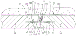
Figure 2 is a cross-sectional view of a wall panel assembly provided in example 1 of the present invention.
Fig. 3 is an enlarged view of a portion a of fig. 2.
Figure 4 is a cross-sectional view of a wall panel assembly provided by embodiment 2 of the present invention.
Figure 5 is a cross-sectional view of a wall panel assembly provided by embodiment 3 of the present invention.
Figure 6 is a cross-sectional view of a wall panel assembly provided in embodiment 4 of the present invention.
Figure 7 is a cross-sectional view of a wall panel assembly provided by embodiment 5 of the present invention.
Figure 8 is a cross-sectional view of a wall panel assembly provided by example 6 of the present invention.
Reference numerals:
10-a connector; 11-a body portion; 12-a connecting part; 121-outer slats; 122-inner slats; 123-slot; 124-punching grooves; 125-screws; 13-a card slot; 14-a groove; 20-a package; 21-a package; 22-a connecting strip; 23-sticking; 30-wallboard; 31-a plug-in part; 32-a docking station; 33-inserting the seam; 100-structural wall.
Detailed Description
In order to make the objects, technical solutions and advantages of the embodiments of the present invention clearer, the technical solutions of the embodiments of the present invention will be clearly and completely described below with reference to the drawings of the embodiments of the present invention. It is to be understood that the embodiments described are only a few embodiments of the present invention, and not all embodiments. All other embodiments, which can be derived by a person skilled in the art from the described embodiments of the invention without any inventive step, are within the scope of protection of the invention.
Unless defined otherwise, technical or scientific terms used herein shall have the ordinary meaning as understood by one of ordinary skill in the art to which this invention belongs. The use of "first," "second," and similar terms in the present application do not denote any order, quantity, or importance, but rather the terms are used to distinguish one element from another. The word "comprising" or "comprises", and the like, means that the element or item listed before the word covers the element or item listed after the word and its equivalents, but does not exclude other elements or items. The terms "connected" or "coupled" and the like are not restricted to physical or mechanical connections, but may include electrical connections, whether direct or indirect. "upper", "lower", "left", "right", and the like are used merely to indicate relative positional relationships, and when the absolute position of the object being described is changed, the relative positional relationships may also be changed accordingly.
To maintain the following description of the embodiments of the present invention clear and concise, a detailed description of known functions and known components of the invention have been omitted.
As shown in fig. 1 to 8, the embodiment of the present invention discloses a connector 10; a connection assembly including the connector 10, the connection assembly including a package 20 in addition to the connector 10; a wall panel assembly comprising the connector assembly, the wall panel assembly comprising a plurality of wall panels 30 in addition to the connector assembly.
A plurality of wall panels 30 are arranged side by side on the outer side of the structural wall 100, and the connecting assembly is arranged between two adjacent wall panels 30.
The connecting piece 10 in the connecting assembly comprises a main body part 11 and a connecting part 12; the connecting portions 12 include two, and two connecting portions 12 are located the both sides of main portion 11 respectively, and two connecting portions 12 all are formed with slot 123, and two slots 123 are towards the side of two adjacent wallboards 30, and the side of two adjacent wallboards 30 corresponds respectively and inserts in two slots 123.
Specifically, each of the two connecting portions 12 includes an outer slat 121 and an inner slat 122, the outer slat 121 and the inner slat are obtained by extending from the main body portion 11, the outer slat 121 and the inner slat 122 are disposed in parallel, the slot 123 is defined between the outer slat 121 and the inner slat 122, and the inner slats 122 of the two connecting portions 12 are used for being attached to the indoor structural wall 100; correspondingly, the side edges of two adjacent wall panels 30 are provided with insertion slits 33, the insertion slits 33 divide the side edges of the wall panels 30 into a butt joint part 32 located at the outer side and an insertion part 31 located at the inner side, the insertion part 31 is inserted into the insertion slot 123, and correspondingly, the outer plate bars 121 of the connecting part 12 extend into the insertion slits 33, so that the two adjacent wall panels 30 form a splicing state.
In the present invention, a locking groove 13 is formed on the outer side of the main body 11, and the locking groove 13 penetrates through the upper and lower ends of the main body 11. The package 20 includes a package portion 21 and a connection bar 22; the sealing portion 21 is used to be disposed in a gap formed between the abutting portions 32 of the side edges of two adjacent wall panels 30; the connecting strip 22 is integrally formed on the inner side of the packaging part 21, the inner side of the connecting strip 22 is integrally formed with a clamping projection 23, the section of the clamping projection 23 is adapted to the section of the clamping groove 13 on the main body part 11, which makes: the sealing element 20 makes the sealing portion 21 connected to the connector 10 via the connecting strip 22 by aligning the locking protrusion 23 with the end of the locking slot 13 and sliding into the locking slot 13, and the locking slot 13 and the locking protrusion 23 cooperate to prevent the sealing portion 21 from separating from the connector 10 in the thickness direction, so that the sealing portion 21 obtains a better positioning effect, and the sealing portion 21 is stably maintained in the gap formed between the two wall plates 30.
To make the abutting portion 32 of the wall plate 30 abut against the packaging portion 21, the insertion portion 31 of the wall plate 30 should be prevented from being inserted into the groove bottom of the slot 123, for example, the insertion portion 31 can be prevented from being inserted into the groove bottom of the slot 123 by the following arrangement: the mating part 31 is made shorter than the abutting part 32.
It should be noted that: the connecting member 10 is fixed to the indoor structural wall 100 by a fastener penetrating the inner slat 122, so that the wall panel 30 is assembled outside the structural wall 100 by the connecting member 10.
In some embodiments, as shown in fig. 3 in combination with fig. 2, a perforated slot 124 is formed on an outer panel surface of one of the inner panels 122 at two sides of the main body 11, the perforated slot 124 is used for passing a screw 125, so as to prevent a nut of the screw 125 from protruding out of an outer panel surface of the inner panel 122, and thus, the abutting portion 32 of the wall board 30 does not interfere with the nut of the screw 125 after being inserted into the slot 123.
In some embodiments, the outer panel surfaces of the outer panels 121 on both sides of the body portion 11 are formed with wavy surfaces, and the outer panels 121 having wavy surfaces are inserted into the insertion slits 33 and are less likely to fall out of the insertion slits 33.
In some embodiments, the inner side of the main body 11 is formed with a groove 14, the groove 14 penetrates through the upper and lower ends of the main body 11, and the groove 14 functions to: water condensed from the moist air present between the structural wall 100 and the wall panel 30 can flow downwardly through the groove 14; at the same time, the recess 14 can reduce the rigidity of the connector 10 to some extent so that assembly errors can be accommodated by micro-deformation.
Several embodiments are listed below for the structure of the encapsulation portion 21 in the encapsulation 20 and the structure of the card slot 13 of the connector 10:
example 1
As shown in fig. 2, in the present embodiment, the cross section of the card slot 13 on the main body 11 of the connector 10 is "cross", and the cross section of the card protrusion 23 on the connecting bar 22 of the package 20 is "cross" matching with the cross section of the card slot 13; the section of the packaging part 21 of the packaging part 20 is U-shaped, and the side plate surfaces of two side plates of the U-shape abut against the end parts of the abutting parts 32.
Example 2
As shown in fig. 4, in the present embodiment, the cross section of the card slot 13 on the main body 11 of the connector 10 is circular, and the cross section of the card protrusion 23 on the connecting bar 22 of the package 20 is circular matching with the cross section of the card slot 13; the section of the packaging part 21 of the packaging part 20 is U-shaped, and the side plate surfaces of two side plates of the U-shape abut against the end parts of the abutting parts 32.
Example 3
As shown in fig. 5, in the present embodiment, the section of the card slot 13 on the main body 11 of the connector 10 is dovetail-shaped, and the section of the card protrusion 23 on the connecting bar 22 of the package 20 is dovetail-shaped matching with the section of the card slot 13; the section of the packaging part 21 of the packaging part 20 is U-shaped, and the side plate surfaces of two side plates of the U-shape abut against the end parts of the abutting parts 32.
Example 4
As shown in fig. 6, in the present embodiment, the cross section of the card slot 13 on the main body 11 of the connector 10 is "cross", and the cross section of the card protrusion 23 on the connecting bar 22 of the package 20 is "cross" matching with the cross section of the card slot 13; the section of the package portion 21 of the package 20 is rectangular, and the side face of the rectangle abuts against the end of the abutting portion 32.
Example 5
As shown in fig. 7, in the present embodiment, the cross section of the card slot 13 on the main body 11 of the connector 10 is circular, and the cross section of the card protrusion 23 on the connecting bar 22 of the package 20 is circular matching with the cross section of the card slot 13; the package portion 21 of the package 20 has a rectangular cross section, and the side face of the rectangle abuts against the end of the abutting portion 32.
Example 6
As shown in fig. 8, in the present embodiment, the section of the card slot 13 on the main body 11 of the connector 10 is dovetail-shaped, and the section of the card protrusion 23 on the connecting bar 22 of the package 20 is dovetail-shaped matching with the section of the card slot 13; the section of the packaging part 21 of the packaging part 20 is U-shaped, and the side plate surfaces of two side plates of the U-shape abut against the end parts of the abutting parts 32.
Moreover, although exemplary embodiments have been described herein, the scope of the present invention includes any and all embodiments based on the present invention with equivalent elements, modifications, omissions, combinations (e.g., of various embodiments across), adaptations or alterations. The elements of the claims are to be interpreted broadly based on the language employed in the claims and not limited to examples described in the present specification or during the prosecution of the application, which examples are to be construed as non-exclusive. It is intended, therefore, that the specification and examples be considered as exemplary only, with a true scope and spirit being indicated by the following claims and their full scope of equivalents.
The above description is intended to be illustrative and not restrictive. For example, the above-described examples (or one or more versions thereof) may be used in combination with each other. For example, other embodiments may be used by those of ordinary skill in the art upon reading the above description. In addition, in the above-described embodiments, various features may be grouped together to streamline the disclosure. This should not be interpreted as an intention that a disclosed feature not claimed is essential to any claim. Rather, inventive subject matter may lie in less than all features of a particular disclosed embodiment. Thus, the following claims are hereby incorporated into the detailed description as examples or embodiments, with each claim standing on its own as a separate embodiment, and it is contemplated that these embodiments may be combined with each other in various combinations or permutations. The scope of the invention should be determined with reference to the appended claims, along with the full scope of equivalents to which such claims are entitled.
The above embodiments are only exemplary embodiments of the present invention, and are not intended to limit the present invention, and the scope of the present invention is defined by the claims. Various modifications and equivalents may be made by those skilled in the art within the spirit and scope of the present invention, and such modifications and equivalents should also be considered as falling within the scope of the present invention.
Claims (11)
1. A connector for connecting two adjacent wall panels, the connector comprising:
a main body portion;
the two connecting parts are respectively positioned at two sides of the main body part, and slots correspondingly facing the two wallboards are respectively formed on the two connecting parts and are respectively used for the two wallboards to be inserted; wherein:
the outer side of the main body part is provided with a clamping groove, and the clamping groove is used for limiting the external part sliding into the clamping groove to be separated from the main body part in the thickness direction of the wall plate.
2. The fitting according to claim 1,
the cross section of the clamping groove is in a cross shape
Or
The section of the clamping groove is circular
Or
The cross section of the clamping groove is in a dovetail shape.
3. A connector according to claim 1, wherein the connecting portion comprises an outer panel and an inner panel extending from the body portion, the outer panel being parallel to the inner panel to define the socket.
4. A connecting member according to claim 3, wherein the outer plate surface of the inner panel of one of the connecting portions of both sides of the main body portion is provided with a perforated groove.
5. A connector according to claim 1, wherein the body portion is formed with a recess in an inner side thereof.
6. A connecting component is used for connecting two adjacent wallboards and is characterized by comprising a connecting piece and a packaging piece;
the connector includes:
the main body part is provided with a clamping groove on the outer side;
the two connecting parts are respectively positioned at two sides of the main body part, and slots correspondingly facing the two wallboards are respectively formed on the two connecting parts and are respectively used for the two wallboards to be inserted;
the package includes:
the packaging part is used for being arranged between the gaps of the two wall plates;
the connecting strip is integrally formed on the inner side of the packaging part, a clamping protrusion matched with the clamping groove is formed on the inner side of the connecting strip, and the clamping protrusion slides into the clamping groove from the upper end or the lower end of the clamping groove.
7. The connection assembly according to claim 6,
the cross section of the clamping groove is in a cross shape, and the cross section of the clamping protrusion is in a cross shape matched with the clamping groove
Or
The cross section of the clamping groove is circular, and the cross section of the clamping protrusion is circular and matched with the clamping groove
Or
The cross section of the clamping groove is in a dovetail shape, and the cross section of the clamping protrusion is in a dovetail shape matched with the clamping groove.
8. A wall panel assembly comprising a plurality of wall panels joined together, further comprising the connection assembly of claim 6 or 7 corresponding to each adjacent two of said wall panels; wherein:
every two adjacent wallboards are respectively and correspondingly inserted into two slots formed on the two connecting parts;
the packaging part is positioned in a gap formed between the side edges of every two adjacent wall boards.
9. The wall panel assembly of claim 8, wherein said connector portion includes an outer panel and an inner panel extending from said body portion, said outer panel being parallel to said inner panel to define said socket;
the side edge of the wallboard is provided with an inserting seam, and the inserting seam divides the side edge of the wallboard into an inserting part positioned on the inner side and a butt joint part positioned on the outer side; the inserting part is inserted into the slot, and the butt joint part abuts against the side face of the packaging part.
10. The wall panel assembly of claim 9, wherein the outer panel surface of the outer panel has a corrugated surface formed thereon.
11. The wall panel assembly of claim 8, wherein the body portion is recessed on an interior side thereof.
Priority Applications (1)
| Application Number | Priority Date | Filing Date | Title |
|---|---|---|---|
| CN201910908569.0A CN112554480A (en) | 2019-09-25 | 2019-09-25 | Connecting piece, coupling assembling and wallboard subassembly |
Applications Claiming Priority (1)
| Application Number | Priority Date | Filing Date | Title |
|---|---|---|---|
| CN201910908569.0A CN112554480A (en) | 2019-09-25 | 2019-09-25 | Connecting piece, coupling assembling and wallboard subassembly |
Publications (1)
| Publication Number | Publication Date |
|---|---|
| CN112554480A true CN112554480A (en) | 2021-03-26 |
Family
ID=75029030
Family Applications (1)
| Application Number | Title | Priority Date | Filing Date |
|---|---|---|---|
| CN201910908569.0A Pending CN112554480A (en) | 2019-09-25 | 2019-09-25 | Connecting piece, coupling assembling and wallboard subassembly |
Country Status (1)
| Country | Link |
|---|---|
| CN (1) | CN112554480A (en) |
Cited By (1)
| Publication number | Priority date | Publication date | Assignee | Title |
|---|---|---|---|---|
| CN114809496A (en) * | 2022-05-16 | 2022-07-29 | 福建小兔快装建筑科技有限公司 | Modular bamboo wood fiber wallboard connection structure |
Citations (11)
| Publication number | Priority date | Publication date | Assignee | Title |
|---|---|---|---|---|
| JPH0960244A (en) * | 1995-08-22 | 1997-03-04 | Nozawa Corp | Seal structure for joint of extruded plates |
| CN1328612A (en) * | 1998-10-06 | 2001-12-26 | 珀屋富朗股份公司 | Flooring material comprising board shaped floor elements which are jointed vertically by means of separate assembly profiles |
| CN201411884Y (en) * | 2009-06-11 | 2010-02-24 | 李新发 | Combined fastening board |
| KR20170069628A (en) * | 2015-12-11 | 2017-06-21 | 주식회사 뉴매트코리아 | Wall rail for installing stretch sheet |
| CN206538963U (en) * | 2017-01-17 | 2017-10-03 | 深圳市优住住区产业化科技发展有限公司 | Wallboard with Hermetical connecting structure |
| CN107268922A (en) * | 2017-06-22 | 2017-10-20 | 嘉兴天美环保集成墙面有限公司 | A kind of assembled wall board |
| CN206971625U (en) * | 2017-06-22 | 2018-02-06 | 嘉兴天美环保集成墙面有限公司 | A kind of assembled wall board being connected firmly |
| CN207079856U (en) * | 2017-07-07 | 2018-03-09 | 霍高文建筑系统(广州)有限公司 | Combined wall board assembling assembly |
| CN208363474U (en) * | 2018-07-03 | 2019-01-11 | 吴云友 | A kind of spliced wallboard |
| CN209194904U (en) * | 2018-09-10 | 2019-08-02 | 天津达因建材有限公司 | Wall panel assembly |
| CN211257657U (en) * | 2019-09-25 | 2020-08-14 | 天津达因建材有限公司 | Connecting piece, coupling assembling and wallboard subassembly |
-
2019
- 2019-09-25 CN CN201910908569.0A patent/CN112554480A/en active Pending
Patent Citations (11)
| Publication number | Priority date | Publication date | Assignee | Title |
|---|---|---|---|---|
| JPH0960244A (en) * | 1995-08-22 | 1997-03-04 | Nozawa Corp | Seal structure for joint of extruded plates |
| CN1328612A (en) * | 1998-10-06 | 2001-12-26 | 珀屋富朗股份公司 | Flooring material comprising board shaped floor elements which are jointed vertically by means of separate assembly profiles |
| CN201411884Y (en) * | 2009-06-11 | 2010-02-24 | 李新发 | Combined fastening board |
| KR20170069628A (en) * | 2015-12-11 | 2017-06-21 | 주식회사 뉴매트코리아 | Wall rail for installing stretch sheet |
| CN206538963U (en) * | 2017-01-17 | 2017-10-03 | 深圳市优住住区产业化科技发展有限公司 | Wallboard with Hermetical connecting structure |
| CN107268922A (en) * | 2017-06-22 | 2017-10-20 | 嘉兴天美环保集成墙面有限公司 | A kind of assembled wall board |
| CN206971625U (en) * | 2017-06-22 | 2018-02-06 | 嘉兴天美环保集成墙面有限公司 | A kind of assembled wall board being connected firmly |
| CN207079856U (en) * | 2017-07-07 | 2018-03-09 | 霍高文建筑系统(广州)有限公司 | Combined wall board assembling assembly |
| CN208363474U (en) * | 2018-07-03 | 2019-01-11 | 吴云友 | A kind of spliced wallboard |
| CN209194904U (en) * | 2018-09-10 | 2019-08-02 | 天津达因建材有限公司 | Wall panel assembly |
| CN211257657U (en) * | 2019-09-25 | 2020-08-14 | 天津达因建材有限公司 | Connecting piece, coupling assembling and wallboard subassembly |
Non-Patent Citations (1)
| Title |
|---|
| 杨正宏等: "《装配式建筑用预制混凝土构件生产与应用技术》", 31 July 2019, 同济大学出版社 * |
Cited By (2)
| Publication number | Priority date | Publication date | Assignee | Title |
|---|---|---|---|---|
| CN114809496A (en) * | 2022-05-16 | 2022-07-29 | 福建小兔快装建筑科技有限公司 | Modular bamboo wood fiber wallboard connection structure |
| CN114809496B (en) * | 2022-05-16 | 2024-02-20 | 福建小兔快装建筑科技有限公司 | Combined bamboo-wood fiber wallboard connecting structure |
Similar Documents
| Publication | Publication Date | Title |
|---|---|---|
| CN211257657U (en) | Connecting piece, coupling assembling and wallboard subassembly | |
| CN112554480A (en) | Connecting piece, coupling assembling and wallboard subassembly | |
| CN104619934A (en) | Building board and method of mounting | |
| KR101325301B1 (en) | Insulating panel and constructing method thereof | |
| US6865092B2 (en) | Front part for electronic plug-in modules | |
| CN113738043A (en) | Keel and wall surface system | |
| CN211817618U (en) | Connecting assembly and wallboard assembly | |
| CN211257644U (en) | Packaging part and wallboard assembly | |
| CN112709391A (en) | Internal corner component and wall corner assembly | |
| CN210395986U (en) | Mosaic fishbone parquet splicing structure | |
| CN112554479B (en) | Connecting assembly and wallboard assembly | |
| CN211817570U (en) | Internal corner component and wall corner assembly | |
| CN212359478U (en) | Window casing | |
| JP6050032B2 (en) | Window connection frame | |
| CN216932422U (en) | Decorative strip auxiliary mounting part | |
| CN112127572A (en) | Shingle nail concatenation subassembly | |
| CN215858758U (en) | Aluminum-wood retaining wall structure | |
| CN218990753U (en) | Wallboard mounting system | |
| CN220539122U (en) | Great wall board and edge covering assembly thereof | |
| CN220620558U (en) | Assembled wall system | |
| JP2006274756A (en) | Door leaf of casing structure | |
| CN214696548U (en) | Background wall | |
| CN215889105U (en) | Adjustable external corner mounting | |
| CN220814667U (en) | Wallboard external corner connecting piece | |
| CN113017456A (en) | Compensation strip and bathroom chassis |
Legal Events
| Date | Code | Title | Description |
|---|---|---|---|
| PB01 | Publication | ||
| PB01 | Publication | ||
| SE01 | Entry into force of request for substantive examination | ||
| SE01 | Entry into force of request for substantive examination | ||
| CB02 | Change of applicant information | ||
| CB02 | Change of applicant information |
Address after: 300270 Tianjin Binhai New Area 960 Qingyi Street, Tianjin Economic and Technological Development Zone Applicant after: Heneng renju Technology (Tianjin) Group Co.,Ltd. Address before: 300270 Tianjin Binhai New Area 960 Qingyi Street, Tianjin Economic and Technological Development Zone Applicant before: TIANJIN DAYIN BUILDING MATERIAL Co.,Ltd. |
|
| RJ01 | Rejection of invention patent application after publication | ||
| RJ01 | Rejection of invention patent application after publication |
Application publication date: 20210326 |