CN112554086B - Warning sign device that river course desilting was used - Google Patents
Warning sign device that river course desilting was used Download PDFInfo
- Publication number
- CN112554086B CN112554086B CN202011533875.XA CN202011533875A CN112554086B CN 112554086 B CN112554086 B CN 112554086B CN 202011533875 A CN202011533875 A CN 202011533875A CN 112554086 B CN112554086 B CN 112554086B
- Authority
- CN
- China
- Prior art keywords
- wall
- cleaning
- water
- brush
- adjusting
- Prior art date
- Legal status (The legal status is an assumption and is not a legal conclusion. Google has not performed a legal analysis and makes no representation as to the accuracy of the status listed.)
- Active
Links
- 238000004140 cleaning Methods 0.000 claims abstract description 112
- 230000007246 mechanism Effects 0.000 claims abstract description 41
- 238000005096 rolling process Methods 0.000 claims abstract description 21
- 230000003014 reinforcing effect Effects 0.000 claims abstract description 8
- XLYOFNOQVPJJNP-UHFFFAOYSA-N water Substances O XLYOFNOQVPJJNP-UHFFFAOYSA-N 0.000 claims description 102
- 239000011358 absorbing material Substances 0.000 claims description 23
- 238000000034 method Methods 0.000 claims description 15
- 230000001502 supplementing effect Effects 0.000 claims description 12
- 230000008569 process Effects 0.000 claims description 10
- 230000006835 compression Effects 0.000 claims description 8
- 238000007906 compression Methods 0.000 claims description 8
- 238000010521 absorption reaction Methods 0.000 claims description 6
- 239000000463 material Substances 0.000 claims description 6
- 239000010802 sludge Substances 0.000 description 26
- 230000009471 action Effects 0.000 description 5
- 230000000694 effects Effects 0.000 description 5
- 230000001105 regulatory effect Effects 0.000 description 4
- 238000005553 drilling Methods 0.000 description 3
- 239000000428 dust Substances 0.000 description 3
- 238000010276 construction Methods 0.000 description 2
- 230000005489 elastic deformation Effects 0.000 description 2
- 238000009825 accumulation Methods 0.000 description 1
- 230000004075 alteration Effects 0.000 description 1
- 230000009286 beneficial effect Effects 0.000 description 1
- 238000010586 diagram Methods 0.000 description 1
- 238000004134 energy conservation Methods 0.000 description 1
- 230000006872 improvement Effects 0.000 description 1
- 230000007774 longterm Effects 0.000 description 1
- 230000004048 modification Effects 0.000 description 1
- 238000012986 modification Methods 0.000 description 1
- 230000002787 reinforcement Effects 0.000 description 1
- 238000006467 substitution reaction Methods 0.000 description 1
- 239000013589 supplement Substances 0.000 description 1
- 239000002699 waste material Substances 0.000 description 1
Images


Classifications
-
- E—FIXED CONSTRUCTIONS
- E01—CONSTRUCTION OF ROADS, RAILWAYS, OR BRIDGES
- E01F—ADDITIONAL WORK, SUCH AS EQUIPPING ROADS OR THE CONSTRUCTION OF PLATFORMS, HELICOPTER LANDING STAGES, SIGNS, SNOW FENCES, OR THE LIKE
- E01F9/00—Arrangement of road signs or traffic signals; Arrangements for enforcing caution
- E01F9/60—Upright bodies, e.g. marker posts or bollards; Supports for road signs
- E01F9/623—Upright bodies, e.g. marker posts or bollards; Supports for road signs characterised by form or by structural features, e.g. for enabling displacement or deflection
- E01F9/646—Upright bodies, e.g. marker posts or bollards; Supports for road signs characterised by form or by structural features, e.g. for enabling displacement or deflection extensible, collapsible or pivotable
-
- B—PERFORMING OPERATIONS; TRANSPORTING
- B08—CLEANING
- B08B—CLEANING IN GENERAL; PREVENTION OF FOULING IN GENERAL
- B08B1/00—Cleaning by methods involving the use of tools
- B08B1/10—Cleaning by methods involving the use of tools characterised by the type of cleaning tool
- B08B1/12—Brushes
-
- B—PERFORMING OPERATIONS; TRANSPORTING
- B08—CLEANING
- B08B—CLEANING IN GENERAL; PREVENTION OF FOULING IN GENERAL
- B08B1/00—Cleaning by methods involving the use of tools
- B08B1/30—Cleaning by methods involving the use of tools by movement of cleaning members over a surface
-
- B—PERFORMING OPERATIONS; TRANSPORTING
- B08—CLEANING
- B08B—CLEANING IN GENERAL; PREVENTION OF FOULING IN GENERAL
- B08B1/00—Cleaning by methods involving the use of tools
- B08B1/30—Cleaning by methods involving the use of tools by movement of cleaning members over a surface
- B08B1/32—Cleaning by methods involving the use of tools by movement of cleaning members over a surface using rotary cleaning members
-
- E—FIXED CONSTRUCTIONS
- E01—CONSTRUCTION OF ROADS, RAILWAYS, OR BRIDGES
- E01F—ADDITIONAL WORK, SUCH AS EQUIPPING ROADS OR THE CONSTRUCTION OF PLATFORMS, HELICOPTER LANDING STAGES, SIGNS, SNOW FENCES, OR THE LIKE
- E01F9/00—Arrangement of road signs or traffic signals; Arrangements for enforcing caution
- E01F9/60—Upright bodies, e.g. marker posts or bollards; Supports for road signs
- E01F9/658—Upright bodies, e.g. marker posts or bollards; Supports for road signs characterised by means for fixing
- E01F9/673—Upright bodies, e.g. marker posts or bollards; Supports for road signs characterised by means for fixing for holding sign posts or the like
- E01F9/685—Subsoil means, e.g. foundations
Landscapes
- Engineering & Computer Science (AREA)
- Architecture (AREA)
- Civil Engineering (AREA)
- Structural Engineering (AREA)
- Cleaning In General (AREA)
Abstract
The invention belongs to the technical field of river channel treatment and discloses a warning board device for river channel dredging, which comprises a base, wherein reinforcing mechanisms are arranged at four corners of the base, two groups of height adjusting mechanisms are arranged on the outer wall of the top of the base, adjusting blocks are fixed on the outer wall of the top of each height adjusting mechanism through bolts, the adjusting blocks are rotatably connected with a fixing frame through adjusting shafts, warning boards are clamped on the inner wall of the fixing frame, a cleaning mechanism is arranged on the outer wall of the fixing frame and comprises two cleaning rollers and rolling gears, cleaning brushes in contact with the warning boards are arranged on the outer side walls of the cleaning rollers, the cleaning rollers and the rolling gears are fixedly connected through the cleaning shafts, the outer walls of the tops of the two cleaning shafts are jointly and rotatably connected with a same support, and a driving device is rotatably connected to the inner wall of the support The silt piece carries out effectual automatic clearance, reduces artifical intensity of labour.
Description
Technical Field
The invention belongs to the technical field of river channel treatment, and particularly relates to a warning board device for river channel dredging.
Background
River course desilting generally refers to administering the river course, belongs to hydraulic engineering, has multiple mode at present to carry out the desilting to the river course: most commonly, the silt deposited at the river bottom is blown and stirred into a turbid water state by mechanical equipment and flows away along with river water, so that the dredging function is achieved. However, the requirement of the method on the water flow speed is high, the dredging of the method is a temporary solution and a permanent solution, only the sludge at a certain position is conveyed downstream, the sludge itself is not reduced, the sludge is still accumulated at a lower position of the downstream water flow to cause sludge accumulation, and a warning board is required to warn passing pedestrians and vehicles during the dredging of the river channel.
Because the warning sign is polluted by bonding such as floating dust, silt easily, need clear up it, general warning sign lacks cleaning device, and to some remote river courses improvement, the warning needs all-weather warning, and the construction is then the construction daytime, to the warning of non-engineering time, if arrange personnel's manual clearance warning sign, occupy the manpower, it is very inconvenient.
Disclosure of Invention
The invention aims to solve the problems, and provides a warning board device for river dredging, which has the advantages of convenience in use and energy conservation.
In order to achieve the purpose, the invention provides the following technical scheme: a warning board device for river channel dredging comprises a base, wherein reinforcing mechanisms are arranged at four corners of the base, two groups of height adjusting mechanisms are arranged on the outer wall of the top of the base, adjusting blocks are fixed on the outer wall of the top of each height adjusting mechanism through bolts, the adjusting blocks are connected with a fixing frame in a rotating mode through adjusting shafts, a warning board is clamped on the inner wall of the fixing frame, a cleaning mechanism is arranged on the outer wall of the fixing frame and comprises two cleaning rollers and rolling gears, cleaning brushes in contact with the warning board are arranged on the outer side walls of the cleaning rollers, the cleaning rollers and the rolling gears are fixedly connected through the cleaning shafts, the outer walls of the tops of the two cleaning shafts are jointly and rotatably connected with the same support, a driving device is rotatably connected to the inner walls of the supports, adjusting plates are fixed on the outer walls of the tops of the supports through bolts, and tooth-shaped grooves are formed in the inner walls of two sides of the fixing frame, the two rolling gears are respectively positioned in the two tooth-shaped grooves and are meshed with teeth inside the two rolling gears; a cavity is arranged in the cleaning shaft, and the cavity at the upper end of the cleaning shaft extends into the adjusting plate and is communicated with a flow guide port in the adjusting plate; the cleaning brush comprises a brush body and a brush head, a cavity in the brush body is communicated with a cavity in the cleaning shaft, and water absorbing materials are arranged in the cavity of the cleaning shaft and the cavity of the cleaning brush; and water supplementing devices are respectively arranged at two ends of the fixed frame, and one-way shutoff valves corresponding to the flow guide ports are arranged on the water supplementing devices.
As a preferred technical scheme of the invention, the reinforcing mechanism comprises a drill bit and a screw, the screw is connected to the inner wall of the base through threads, and the drill bit is welded on the outer wall of the bottom of the screw.
In a preferred embodiment of the present invention, the drill has a maximum diameter equal to the diameter of the screw.
As a preferred technical scheme of the invention, the outer wall of the top of the screw rod is provided with a clamping groove, and the inner wall of the clamping groove is clamped with a handle.
As a preferred technical scheme of the invention, the driving device comprises a double-shaft stepping motor, output shafts at two ends of the double-shaft stepping motor are respectively connected with a driving gear, and the driving gears are connected with the bracket through connecting shafts; and a fixed rack meshed with the driving gear is arranged above the fixed frame.
As a preferred technical scheme of the invention, the height adjusting mechanism comprises a fixed sleeve and a telescopic column, the fixed sleeve is welded on the outer wall of the top of the base, the telescopic column is movably connected on the inner wall of the fixed sleeve, the inner walls of the fixed sleeve and the telescopic column are respectively provided with a second height adjusting hole and a first height adjusting hole which are equidistant and mutually matched, and one of the first height adjusting hole and the first height adjusting hole is inserted into the inner wall of the second height adjusting hole to form the same elastic pin I.
As a preferred technical scheme of the invention, the outer wall of one of the adjusting shafts is sleeved with a locking disc, the inner wall of the locking disc is provided with angle adjusting holes II in a circular array, the inner wall of one of the adjusting blocks is provided with angle adjusting holes I which correspond to the angle adjusting holes II one to one, and one elastic pin II is inserted into the inner wall of one of the angle adjusting holes I and the angle adjusting hole II.
As a preferred technical scheme of the invention, the brush body comprises a fixed body and a telescopic body, the telescopic body is sleeved in a cavity of the fixed body, and the end part of the telescopic body is connected with a limiting ring on the inner wall of the fixed body through a compression spring.
As a preferable technical scheme of the invention, the water absorption material in the telescopic body is fixedly connected with the inner wall of the telescopic body, and the brush head is sleeved on the outer wall of the telescopic body.
As a preferred technical scheme of the invention, the water supplementing device comprises a water tank, a water collecting tank is arranged above the water tank, and the water collecting tank is communicated with the inside of the water tank through a through hole.
Compared with the prior art, the invention has the following beneficial effects:
1. according to the invention, the driving device is arranged, the double-shaft motor of the driving device is controlled to work, the double-shaft motor drives the support to reciprocate through the driving gear, the support drives the rolling gear to be meshed with the tooth-shaped groove to reciprocate through the cleaning shaft, and further, the rolling gear is driven by the cleaning shaft, the cleaning roller rotates and reciprocates simultaneously, so that the cleaning brush on the cleaning roller cleans the warning plate, and the device can clean the warning plate timely and automatically without people, liberates manpower and enables the warning plate to realize the real-time warning effect.
2. According to the invention, the screw rod is arranged, before the device is placed, the screw rod is screwed to the uppermost position, after the device is placed, a worker stands on the base, the handle is screwed to drive the screw rod to rotate, then the screw rod is driven to go deep into the ground through the drilling action of the drill bit, and the four screw rods are all rotated to the lowest position through the steps to complete the fixation of the device.
3. According to the invention, through the arrangement of the height adjusting mechanism, when the height needs to be adjusted, the first elastic pin is pulled out, the height of the telescopic column is adjusted, the flexibility of the device is improved, when the height needs to be adjusted, two pairs of the first height adjusting hole and the second height adjusting hole are ensured, and the height adjustment can be completed by inserting the first elastic pin along the aligned first height adjusting hole and the second height adjusting hole, so that the height adjustment is more convenient.
4. According to the invention, the locking disc is arranged, when the angle needs to be adjusted, the elastic pin II is pulled out, the angle can be adjusted by rotating the fixing frame, the flexibility of the device is further improved, when the angle needs to be adjusted, the angle adjusting hole I and the angle adjusting hole II can be aligned, the angle can be locked by inserting the elastic pin II into one pair of the angle adjusting hole I and the angle adjusting hole II, and the process is convenient.
5. According to the invention, the cavity and the water absorbing material are arranged in the cleaning shaft, the cavity at the upper end of the cleaning shaft extends into the adjusting plate and is communicated with the flow guide port in the adjusting plate, when the cleaning mechanism moves to one end of the fixing frame in the process of driving the cleaning mechanism to reciprocate by the driving device, the flow guide port is inserted into the one-way shutoff valve, the cavity in the cleaning shaft is communicated with the water tank of the water supplementing device, water in the water tank is absorbed by the water absorbing material in the cleaning shaft, the absorbed water further flows onto the water absorbing material in the cleaning brush, and the cleaning brush can infiltrate floating dust and sludge blocks on the warning plate after absorbing water, so that the cleaning effect of the warning board is improved.
6. The structure of the cleaning brush is further optimized, the brush body comprises a fixed body and a telescopic body, the telescopic body is sleeved in a cavity of the fixed body, and the end part of the telescopic body is connected with a limiting ring on the inner wall of the fixed body through a compression spring. When the cleaning brush is contacted with a larger solidified harder sludge block on the warning board, the sludge block extrudes the brush head, the brush head is extruded and deformed, water absorbed in the brush head is extruded out to infiltrate the sludge block and soften the sludge block, and the brush head cleans the sludge block under the driving of the rotation of the cleaning roller; secondly, after the brush head is extruded to the maximum deformation, the brush head extrudes the telescopic body connected with the brush head, and the telescopic body extrudes the compression spring and retracts into the fixed body, so that the situation that the surface of the warning board is damaged due to the fact that the brush body is in direct rigid contact with the sludge block and extrudes and cleans the sludge block is avoided; on the other hand, the water absorbing material fixedly connected with the telescopic body in the telescopic body is further extruded, more water can be extruded to infiltrate the sludge blocks, so that the sludge blocks are softened, the subsequent cleaning brush can be conveniently and effectively cleaned, and the cleaning effect of the cleaning brush can be further improved.
Drawings
FIG. 1 is a schematic view of the overall structure of the present invention;
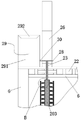
FIG. 2 is a schematic view of a stiffening mechanism according to the present invention;
FIG. 3 is a schematic view of the height adjustment mechanism of the present invention;
FIG. 4 is a schematic view of the locking plate of the present invention;
FIG. 5 is a schematic view of the cleaning mechanism of the present invention;
FIG. 6 is an enlarged partial view of A in FIG. 5 according to the present invention;
FIG. 7 is a front partial cross-sectional view of the cleaning mechanism and refill apparatus of the present invention;
fig. 8 is a partial enlarged structural diagram of B in fig. 7 according to the present invention.
In the figure: 1. a base; 2. a reinforcement mechanism; 3. a height adjustment mechanism; 4. a cleaning mechanism; 5. a warning board; 6. a fixing frame; 7. an adjusting block; 8. an adjustment shaft; 9. a drill bit; 10. a screw; 11. a handle; 12. fixing the sleeve; 13. a telescopic column; 14. a first height adjusting hole; 15. a first elastic pin; 16. a second height adjusting hole; 17. a first angle adjusting hole; 18. a second angle adjusting hole; 19. a second elastic pin; 20. a cleaning brush; 201. a brush body; 202. a brush head; 203. a water-absorbing material; 204. a fixed body; 205. a telescopic body; 206. a compression spring; 207. a limiting ring; 21. a cleaning roller; 22. a rolling gear; 23. cleaning the shaft; 24. a drive device; 25. a support; 26. an adjusting plate; 27. a toothed groove; 28. a flow guide port; 29. a water replenishing device; 291. a water tank; 292. a water collection tank; 30. a one-way shutoff valve.
Detailed Description
The technical solutions in the embodiments of the present invention will be clearly and completely described below with reference to the drawings in the embodiments of the present invention, and it is obvious that the described embodiments are only a part of the embodiments of the present invention, and not all of the embodiments. All other embodiments, which can be derived by a person skilled in the art from the embodiments given herein without making any creative effort, shall fall within the protection scope of the present invention.
As shown in fig. 1 to 8, the invention provides a warning board device for river dredging, which comprises a base 1, wherein reinforcing mechanisms 2 are arranged at four corners of the base 1, two sets of height adjusting mechanisms 3 are arranged on the outer wall of the top of the base 1, adjusting blocks 7 are fixed on the outer wall of the top of the height adjusting mechanisms 3 through bolts, the adjusting blocks 7 are rotatably connected with a fixed frame 6 through adjusting shafts 8, a warning board 5 is clamped on the inner wall of the fixed frame 6, a cleaning mechanism 4 is arranged on the outer wall of the fixed frame 6, the cleaning mechanism 4 comprises two cleaning rollers 21 and a rolling gear 22, a cleaning brush 20 which is in contact with the warning board 5 is arranged on the outer wall of each cleaning roller 21, the cleaning rollers 21 and the rolling gear 22 are fixedly connected through cleaning shafts 23, the outer walls of the tops of the two cleaning shafts 23 are rotatably connected with a same bracket 25, a driving device 24 is rotatably connected on the inner wall of the bracket 25, the driving device 24 comprises a stepping motor, output shafts at two ends of the double-shaft stepping motor are respectively connected with a driving gear, the driving gear is connected with a bracket 25 through a connecting shaft, and the connecting shaft is rotationally connected with the bracket 25; a fixed rack which is meshed with the driving gear is arranged above the fixed frame 6. The double-shaft stepping motor rotates forwards or backwards to drive the driving gear to rotate forwards or backwards, and the driving gear rotating forwards or backwards is meshed with the fixed rack to reciprocate above the fixed frame 6 so as to drive the support 25 to reciprocate. The top outer wall of support 25 is fixed with regulating plate 26 through the bolt, and regulating plate 26 divide into two parts about mutually independent, and the lower part of regulating plate 26 is connected with clean axle 23, realizes the clearance function of device, and the upper portion of regulating plate 26 is equipped with solar cell panel, can provide the electric energy for biax step motor and controller. The upper part and the lower part of the adjusting plate 26 are connected through a hinge and a telescopic rod, so that the angle of the solar cell panel on the upper part of the adjusting plate 26 can be adjusted, and solar energy can be absorbed by the solar cell panel.
Tooth-shaped grooves 27 are formed in the inner walls of two sides of the fixing frame 6, the two rolling gears 22 are respectively located in the two tooth-shaped grooves 27 and are meshed with teeth inside the two tooth-shaped grooves, the double-shaft motor drives the support 25 to reciprocate through the driving gear, the support 25 drives the rolling gears 22 to be meshed with the tooth-shaped grooves 27 to reciprocate through the cleaning shaft 23, and then the cleaning shaft 23 drives the rolling gears 22 to reciprocate while the cleaning roller 21 rotates, so that the warning plate 5 is cleaned repeatedly.
When using, place this device in the river side, and the reinforcing mechanism 2 of four groups of accessible is fixed with it, its height-adjusting mechanism 3 of accessible adjusts its height afterwards, then will warn the content and put up on warning board 5, at the warning in-process, the biax motor passes through drive gear and drives support 25 reciprocating motion, support 25 drives rolling gear 22 meshing tooth form groove 27 reciprocating motion through cleaning axle 23, and then realizes that cleaning axle 23 drives rolling gear 22, cleaning roller 21 pivoted reciprocating motion simultaneously, clear up warning board 5.
The reinforcing mechanism 2 comprises a drill bit 9 and a screw rod 10, the screw rod 10 is connected to the inner wall of the base 1 through threads, the drill bit 9 is welded to the outer wall of the bottom of the screw rod 10, the maximum diameter of the drill bit 9 is equal to the diameter of the screw rod 10, a clamping groove is formed in the outer wall of the top of the screw rod 10, and a handle 11 is clamped on the inner wall of the clamping groove; this device, through being provided with screw rod 10, before the device is placed, screw rod 10 is twisted to the position on the top, the device is placed the back, the workman stands on base 1, and through twisting handle 11 drive screw rod 10 and rotate, drilling effect through drill bit 9 is deepened underground with screw rod 10 afterwards, all rotate four screw rods 10 to the lower with this step, accomplish the fixed of device, when the device receives external force this moment, it can take place pivoted trend, and the straight line is deep underground during four screw rods 10, can't rotate to its restriction, can effectual assurance device's stability, finish when using, screw rod 10 can be taken away the device away to back respectively.
The height adjusting mechanism 3 comprises a fixed sleeve 12 and a telescopic column 13, the fixed sleeve 12 is welded on the outer wall of the top of the base 1, the telescopic column 13 is movably connected on the inner wall of the fixed sleeve 12, the inner walls of the fixed sleeve 12 and the telescopic column 13 are respectively provided with a second height adjusting hole 16 and a first height adjusting hole 14 which are equidistant and mutually matched, and the inner walls of the first height adjusting hole 14 and the second height adjusting hole 16 are inserted with a same elastic pin 15; when the height needs to be adjusted, the first elastic pin 15 is pulled out, the height of the telescopic column 13 is adjusted, the flexibility of the device is improved, when the height needs to be adjusted, one of the height adjusting holes 14 and the height adjusting holes 16 are aligned with each other, and the height can be adjusted by inserting the first elastic pin 15 into the height adjusting holes 14 and the height adjusting holes 16 which are aligned, so that the height can be adjusted conveniently.
The outer wall of one of the adjusting shafts 8 is sleeved with a locking disc, the inner wall of the locking disc is provided with a circular array of angle adjusting holes II 18, the inner wall of one of the adjusting blocks 7 is provided with angle adjusting holes I17 which correspond to the angle adjusting holes II 18 one by one, and the inner walls of one of the angle adjusting holes I17 and the angle adjusting holes II 18 are inserted with the same elastic pin II 19; when needs angle regulation, extract elasticity pin two 19, rotate fixed frame 6, can adjust the angle, further improved the flexibility of device, when adjusting to needs angle, guarantee that angle regulation hole one 17 can align with angle regulation hole two 18, insert elasticity pin two 19 along one of them pair of angle regulation hole one 17 and angle regulation hole two 18 and can lock the angle, the process is also comparatively convenient.
In order to clean up the pollution to warning board 5 caused by floating dust, silt, etc., reduce the workload of artificial cleaning, the device has the function of timing automatic cleaning through design. A cavity is arranged in the cleaning shaft 23, the cavity at the upper end of the cleaning shaft 23 extends into the adjusting plate 26 and is communicated with a diversion port 28 in the adjusting plate 26, and the diversion ports 28 are symmetrically arranged at two sides of the lower part of the adjusting plate 26 and are communicated with the cavity of the cleaning shaft 23; the cleaning brush 20 comprises a brush body 201 and a brush head 202, a cavity in the brush body 201 is communicated with a cavity in the cleaning shaft 23, and water absorbing materials 203 are arranged in the cavity of the cleaning shaft 23 and the cavity of the cleaning brush 20; two ends of the fixed frame 6 are respectively provided with a water supplementing device 29, and the water supplementing device 29 is provided with a one-way shutoff valve 30 corresponding to the diversion port 28. In the process that the driving device 24 drives the cleaning mechanism 4 to reciprocate, when the cleaning mechanism 4 moves to one end of the fixed frame 6, the flow guide opening 28 is inserted into the one-way shutoff valve 30, so that the cavity inside the cleaning shaft 23 is communicated with the water tank 291 of the water replenishing device 29, water in the water tank 291 is absorbed by the water absorbing material 203 in the cleaning shaft 23, and the absorbed water further flows onto the water absorbing material in the cleaning brush 20 to prepare for the cleaning of the warning board 5 by the cleaning brush 20. The controller controls the rotation time of the double-shaft stepping motor so as to realize that the diversion port 28 is inserted into the one-way shutoff valve 30 when the driving device 24 drives the cleaning mechanism 4 to move to one end of the fixed frame 6. Meanwhile, the size of the water outlet aperture of the one-way shutoff valve 30 is controlled, the amount of water absorbed by the water absorbing material 203 is controlled, the water absorbing material 203 is prevented from absorbing excessive water and flowing to the outside to cause water source waste, the water supplementing frequency of the water supplementing device 29 is increased, and the workload of personnel is increased.
After the water absorption material 203 in the brush body 201 absorbs water, the water absorption material 203 conveys the water to the brush head 202, the brush head 202 is made of water absorption sponge, and the brush head 202 is connected with the water absorption material 203 in the brush body 201, so that the brush head 202 can absorb water smoothly, and the warning board 5 can be cleaned.
In order to ensure the cleaning effect of the brush body 201, when the device is installed, the distance from the cleaning roller 21 to the warning plate 5 is controlled, so that the brush head 202 is tightly pressed on the warning plate 5, and the brush head 202 can complete the cleaning of the whole surface of the warning plate 5 in the reciprocating process. However, after the warning board 5 is stuck with a large or solidified sludge block, when the brush head 202 of the brush body 201 is in contact with the sludge block, squeezed and forcedly cleaned when the warning board 5 is cleaned, the brush head 202 is squeezed to generate elastic deformation, the brush body 20 can be forcedly cleaned in contact with the sludge block, the surface of the warning board 5 may be damaged, and the warning board 5 can be damaged due to long-term accumulated damage, so that the normal use cannot be realized. The brush body 20 is therefore further optimized: the brush body 201 comprises a fixed body 204 and a telescopic body 205, the telescopic body 205 is sleeved in a cavity of the fixed body 204, and the end part of the telescopic body 205 is connected with a limit ring 207 on the inner wall of the fixed body 204 through a compression spring 206. The water absorbing material in the telescopic body 205 is fixedly connected with the inner wall of the telescopic body 205, the brush head 202 is sleeved on the outer wall of the telescopic body 205, and the brush head 202 is connected with the water absorbing material 203 in the telescopic body 205. When the cleaning brush 20 is in contact with the larger solidified harder sludge block on the warning board 5, the brush head 202 is extruded by the sludge block at first, the brush head 202 is extruded and deformed, water absorbed in the brush head is extruded out to infiltrate the sludge block and soften the sludge block, and meanwhile, the brush head 202 cleans the sludge block under the driving of the rotation of the cleaning roller 21; secondly, after the brush head 202 is extruded to the maximum deformation, the brush head 202 extrudes the telescopic body 205 connected with the brush head, and the telescopic body 205 extrudes the compression spring 206 and retracts into the fixed body 204, so that the situation that the surface of the warning board 5 is damaged due to the fact that the brush body 201 is directly and rigidly contacted with sludge blocks and the sludge blocks are extruded and cleaned is avoided on one hand; on the other hand, in the process that the telescopic body 205 retracts into the fixed body 204, the water absorbing material fixedly connected with the telescopic body 205 in the telescopic body 205 is further extruded, so that more water can be extruded to infiltrate and soften the sludge blocks, and the subsequent cleaning brush 20 can conveniently and effectively clean the sludge blocks. With the rotation of the cleaning roller 21, when the cleaning brush 20 pressed and contacted with the warning board 5 rotates to a position where the cleaning brush is no longer contacted with the surface of the warning board 5, the compression spring 206 recovers elastic deformation to push the telescopic body 205 to extend out of the fixed body 204, the water absorbing material 203 in the telescopic body 205 is contacted with a pressurized state and absorbs water from the water absorbing material 203 in the cleaning shaft 23, and meanwhile, the brush head 202 recovers deformation and absorbs water through the water absorbing material 203 in the telescopic body 205, so that preparation is made for cleaning the surface of the warning board 5 next time.
The water replenishing device 29 comprises a water tank 291, a water collecting tank 292 is arranged above the water tank 291, and the water collecting tank 292 is communicated with the inside of the water tank 291 through a through hole. On one hand, the water collecting groove 292 can collect rainwater and flow into the water tank 291 through the through hole to supplement water for the water tank 291; on the other hand, water can be manually added into the water collecting tank 292 according to the requirement, so that the water quantity in the water tank is ensured to be sufficient.
The working principle and the using process of the invention are as follows: when the device is installed, the screw rods 10 are screwed to the uppermost position, after the device is placed, an installer stands on the base 1, the handle 11 is screwed to drive the screw rods 10 to rotate, then the screw rods 10 are deeply buried underground through the drilling action of the drill bit 9, the four screw rods 10 are all rotated to the lowest position through the step, the fixing of the device is completed, then the first elastic pin 15 is pulled out, the height of the telescopic column 13 is adjusted, when the required height is adjusted, one height adjusting hole 14 and the second height adjusting hole 16 are ensured to be aligned, the first elastic pin 15 is inserted into the aligned height adjusting hole 14 and the second height adjusting hole 16 to complete the height adjustment, then the second elastic pin 19 is pulled out, the fixed frame 6 is rotated to adjust the angle, when the required angle is adjusted, the first angle adjusting hole 17 and the second angle adjusting hole 18 are ensured to be aligned, and the locking can be realized by inserting the second elastic pin 19 into the first angle adjusting hole 17 and the second angle adjusting hole 18 to lock And finally, warning contents are pasted on the warning board 5, then the controller starts the double-shaft motor to work and drives the support 25 to reciprocate through the driving gear, the support 25 drives the rolling gear 22 to be meshed with the tooth-shaped groove 27 to reciprocate through the cleaning shaft 23, and then the cleaning shaft 23 drives the rolling gear 22 and the cleaning roller 21 to rotate and reciprocate simultaneously, so that the cleaning brush 20 on the cleaning roller 21 cleans the warning board 5.
It is noted that, herein, relational terms such as first and second, and the like may be used solely to distinguish one entity or action from another entity or action without necessarily requiring or implying any actual such relationship or order between such entities or actions. Also, the terms "comprises," "comprising," or any other variation thereof, are intended to cover a non-exclusive inclusion, such that a process, method, article, or apparatus that comprises a list of elements does not include only those elements but may include other elements not expressly listed or inherent to such process, method, article, or apparatus.
Although embodiments of the present invention have been shown and described, it will be appreciated by those skilled in the art that changes, modifications, substitutions and alterations can be made in these embodiments without departing from the principles and spirit of the invention, the scope of which is defined in the appended claims and their equivalents.
Claims (9)
1. The utility model provides a warning sign device that river course desilting was used, includes base (1), its characterized in that: the four corners of the base (1) are provided with reinforcing mechanisms (2), the outer wall of the top of the base (1) is provided with two groups of height adjusting mechanisms (3), adjusting blocks (7) are fixed on the outer wall of the top of each height adjusting mechanism (3) through bolts, the adjusting blocks (7) are rotatably connected with a fixed frame (6) through adjusting shafts (8), and warning plates (5) are clamped on the inner wall of the fixed frame (6); the cleaning device is characterized in that a cleaning mechanism (4) is arranged on the outer wall of the fixed frame (6), the cleaning mechanism (4) comprises two cleaning rollers (21) and rolling gears (22), cleaning brushes (20) which are in contact with the warning plate (5) are arranged on the outer side walls of the cleaning rollers (21), the outer walls of the tops of the two cleaning shafts (23) are connected with a same support (25) in a rotating mode, the inner wall of the support (25) is connected with a driving device (24) in a rotating mode, an adjusting plate (26) is fixed on the outer wall of the top of the support (25) through bolts, tooth-shaped grooves (27) are formed in the inner walls of the two sides of the fixed frame (6), and the two rolling gears (22) are located in the two tooth-shaped grooves (27) respectively and are meshed with teeth inside the two rolling gears; a cavity is arranged in the cleaning shaft (23), and the cavity at the upper end of the cleaning shaft (23) extends into the adjusting plate (26) and is communicated with a flow guide opening (28) in the adjusting plate (26); the cleaning brush (20) comprises a brush body (201) and a brush head (202), a cavity in the brush body (201) is communicated with a cavity in the cleaning shaft (23), and water absorbing materials (203) are arranged in the cavity of the cleaning shaft (23) and the cavity of the cleaning brush (20); two ends of the fixed frame (6) are respectively provided with a water supplementing device (29), and the water supplementing devices are provided with one-way shutoff valves (30) corresponding to the diversion ports (28);
the water supplementing device (29) comprises a water tank, a water collecting tank (292) is arranged above the water tank (291), and the water collecting tank (292) is communicated with the inside of the water tank (291) through a through hole; in the process that the driving device (24) drives the cleaning mechanism (4) to reciprocate, when the cleaning mechanism (4) moves to one end of the fixing frame (6), the flow guide port (28) is inserted into the one-way shutoff valve (30), so that a cavity inside the cleaning shaft (23) is communicated with a water tank (291) of the water supplementing device (29), water in the water tank (291) is absorbed by the water absorbing material (203) inside the cleaning shaft (23), the absorbed water further flows onto the water absorbing material inside the cleaning brush (20), after the water absorbing material (203) inside the brush body (201) absorbs water, the water absorbing material (203) conveys the water onto the brush head (202), the brush head (202) is made of a water absorbing sponge material, and the brush head (202) is connected with the water absorbing material (203) inside the brush body (201), so that the brush head (202) can be ensured to be smooth, and the warning water absorbing plate (5) can be cleaned.
2. A warning sign device for river dredging according to claim 1, wherein: reinforcing mechanism (2) include drill bit (9) and screw rod (10), screw rod (10) pass through threaded connection on the inner wall of base (1), and drill bit (9) welds on the bottom outer wall of screw rod (10).
3. A warning sign device for river dredging according to claim 2, wherein: the maximum diameter of the drill bit (9) is equal to the diameter of the screw (10).
4. A warning sign device for river dredging according to claim 3, wherein: the outer wall of the top of the screw rod (10) is provided with a clamping groove, and the inner wall of the clamping groove is clamped with a handle (11).
5. A warning sign device for river dredging according to claim 1, wherein: the driving device (24) comprises a double-shaft stepping motor, output shafts at two ends of the double-shaft stepping motor are respectively connected with a driving gear, and the driving gears are connected with the bracket (25) through connecting shafts; and a fixed rack meshed with the driving gear is arranged above the fixed frame (6).
6. A warning sign device for river dredging according to claim 1, wherein: height adjusting mechanism (3) are including fixed sleeve (12) and flexible post (13), fixed sleeve (12) weld on the top outer wall of base (1), flexible post (13) swing joint is on the inner wall of fixed sleeve (12), just equidistant and height control hole two (16) and height control hole one (14) of mutually supporting are seted up respectively to fixed sleeve (12) and flexible post (13) inner wall, one of them height control hole one (14) are pegged graft with the inner wall of height control hole two (16) and are had same elasticity pin one (15).
7. A warning sign device for river dredging according to claim 1, wherein: the outer wall of one of the adjusting shafts (8) is sleeved with a locking disc, the inner wall of the locking disc is provided with two angle adjusting holes (18) in a circular array, the inner wall of one of the adjusting blocks (7) is provided with one angle adjusting hole (17) in one-to-one correspondence with the two angle adjusting holes (18), and the inner wall of one of the angle adjusting holes (17) and the inner wall of the two angle adjusting holes (18) are inserted with one elastic pin (19).
8. A warning sign device for river dredging according to claim 1, wherein: the brush body (201) comprises a fixed body (204) and a telescopic body (205), the telescopic body (205) is sleeved in a cavity of the fixed body (204), and the end part of the telescopic body (205) is connected with a limiting ring (207) on the inner wall of the fixed body (204) through a compression spring (206).
9. A warning sign device for river dredging according to claim 8, wherein: the water absorption material in the telescopic body (205) is fixedly connected with the inner wall of the telescopic body (205), and the brush head (202) is sleeved on the outer wall of the telescopic body (205).
Priority Applications (1)
| Application Number | Priority Date | Filing Date | Title |
|---|---|---|---|
| CN202011533875.XA CN112554086B (en) | 2020-12-22 | 2020-12-22 | Warning sign device that river course desilting was used |
Applications Claiming Priority (1)
| Application Number | Priority Date | Filing Date | Title |
|---|---|---|---|
| CN202011533875.XA CN112554086B (en) | 2020-12-22 | 2020-12-22 | Warning sign device that river course desilting was used |
Publications (2)
| Publication Number | Publication Date |
|---|---|
| CN112554086A CN112554086A (en) | 2021-03-26 |
| CN112554086B true CN112554086B (en) | 2022-05-03 |
Family
ID=75031472
Family Applications (1)
| Application Number | Title | Priority Date | Filing Date |
|---|---|---|---|
| CN202011533875.XA Active CN112554086B (en) | 2020-12-22 | 2020-12-22 | Warning sign device that river course desilting was used |
Country Status (1)
| Country | Link |
|---|---|
| CN (1) | CN112554086B (en) |
Families Citing this family (3)
| Publication number | Priority date | Publication date | Assignee | Title |
|---|---|---|---|---|
| CN113458047B (en) * | 2021-06-24 | 2022-10-25 | 安徽机电职业技术学院 | Automatic cleaning device for intelligent manufacturing shock absorber |
| CN115228786B (en) * | 2022-08-09 | 2023-10-13 | 北京兴百建设安装集团有限公司 | Fire control pilot lamp |
| CN115306196B (en) * | 2022-08-18 | 2023-08-15 | 浙江八方电信有限公司 | Urban road multi-pole integrated intelligent communication tower |
Citations (9)
| Publication number | Priority date | Publication date | Assignee | Title |
|---|---|---|---|---|
| JPH09158133A (en) * | 1995-12-05 | 1997-06-17 | Azuma Shokai:Kk | Cleaning device of display board |
| CN108442267A (en) * | 2018-05-18 | 2018-08-24 | 蔡伟展 | A kind of auxiliary warning sign of channel cleanout |
| CN108606713A (en) * | 2018-05-10 | 2018-10-02 | 林微雨 | A kind of drum-type automatic window-cleaning brush |
| CN109275450A (en) * | 2018-11-22 | 2019-01-29 | 花王生态工程股份有限公司 | A kind of Landscape River movable green belt |
| CN208701546U (en) * | 2018-06-01 | 2019-04-05 | 武汉市通盛交通设施有限公司 | A kind of novel gantry height-limiting frame |
| CN210015626U (en) * | 2019-06-23 | 2020-02-04 | 王国柱 | Safety indicator board for petroleum extraction construction |
| CN210067912U (en) * | 2018-11-30 | 2020-02-14 | 海南梵思科技有限公司 | Self-cleaning door and window |
| CN211200143U (en) * | 2019-10-13 | 2020-08-07 | 熊师远 | Traffic engineering warning device |
| CN211973260U (en) * | 2020-01-08 | 2020-11-20 | 王丰 | Guardrail is used in municipal administration convenient to equipment |
Family Cites Families (3)
| Publication number | Priority date | Publication date | Assignee | Title |
|---|---|---|---|---|
| CN106419220B (en) * | 2016-11-23 | 2019-04-12 | 新昌县佛虑机械配件厂 | A kind of bus stop board seat with self-cleaning function |
| CN210062483U (en) * | 2019-02-28 | 2020-02-14 | 永春县梓涵生态农业有限公司 | White board with cleaning device |
| CN210574791U (en) * | 2019-08-09 | 2020-05-19 | 南通晶与电子科技有限公司 | Spliced LED display screen |
-
2020
- 2020-12-22 CN CN202011533875.XA patent/CN112554086B/en active Active
Patent Citations (9)
| Publication number | Priority date | Publication date | Assignee | Title |
|---|---|---|---|---|
| JPH09158133A (en) * | 1995-12-05 | 1997-06-17 | Azuma Shokai:Kk | Cleaning device of display board |
| CN108606713A (en) * | 2018-05-10 | 2018-10-02 | 林微雨 | A kind of drum-type automatic window-cleaning brush |
| CN108442267A (en) * | 2018-05-18 | 2018-08-24 | 蔡伟展 | A kind of auxiliary warning sign of channel cleanout |
| CN208701546U (en) * | 2018-06-01 | 2019-04-05 | 武汉市通盛交通设施有限公司 | A kind of novel gantry height-limiting frame |
| CN109275450A (en) * | 2018-11-22 | 2019-01-29 | 花王生态工程股份有限公司 | A kind of Landscape River movable green belt |
| CN210067912U (en) * | 2018-11-30 | 2020-02-14 | 海南梵思科技有限公司 | Self-cleaning door and window |
| CN210015626U (en) * | 2019-06-23 | 2020-02-04 | 王国柱 | Safety indicator board for petroleum extraction construction |
| CN211200143U (en) * | 2019-10-13 | 2020-08-07 | 熊师远 | Traffic engineering warning device |
| CN211973260U (en) * | 2020-01-08 | 2020-11-20 | 王丰 | Guardrail is used in municipal administration convenient to equipment |
Also Published As
| Publication number | Publication date |
|---|---|
| CN112554086A (en) | 2021-03-26 |
Similar Documents
| Publication | Publication Date | Title |
|---|---|---|
| CN112554086B (en) | Warning sign device that river course desilting was used | |
| CN110803727A (en) | Grid for sewage treatment convenient to installation clearance | |
| CN211656084U (en) | Energy-saving and environment-friendly power generation device | |
| CN220862293U (en) | Light stores up and fills integrated device with self-cleaning function | |
| CN209482282U (en) | A kind of collection device of water conservancy river floating refuse | |
| CN111245354A (en) | Solar photovoltaic panel with cleaning function | |
| CN114809543B (en) | Auxiliary filling equipment for ceramic tile gaps | |
| CN215801496U (en) | Rotation type aquatic ecology prosthetic devices with view effect | |
| CN206706871U (en) | A kind of sludge scavenging device of steam turbine | |
| CN206526004U (en) | A kind of building curtain wall automatic flushing device | |
| CN214033886U (en) | Rainwater collection device with angle adjusting structure for building | |
| CN112227323B (en) | River channel pollution discharge device with cleaning structure for bridge construction | |
| CN208267250U (en) | A kind of intelligent construction managing device | |
| CN208908431U (en) | A kind of solar energy green building | |
| CN221702156U (en) | Municipal road sound insulation wall | |
| CN221255404U (en) | Sewage disposal device for hydraulic engineering | |
| CN216369152U (en) | Greenhouse maintenance device for photovoltaic power generation | |
| CN218691971U (en) | Waste recovery structure for timber structure engineering construction | |
| CN216625643U (en) | Adjusting device for inclination angle of photovoltaic panel | |
| CN215888556U (en) | Sponge city oozes row structure | |
| CN217678899U (en) | Trash rack for hydraulic engineering | |
| CN114749398B (en) | Photovoltaic new energy device convenient to wash adjustment | |
| CN117544102B (en) | Self-cleaning type photovoltaic panel | |
| CN217228854U (en) | Convenient clear outdoor fine plastic garbage bin of xuan | |
| CN221507725U (en) | Outdoor bill-board of convenient maintenance |
Legal Events
| Date | Code | Title | Description |
|---|---|---|---|
| PB01 | Publication | ||
| PB01 | Publication | ||
| SE01 | Entry into force of request for substantive examination | ||
| SE01 | Entry into force of request for substantive examination | ||
| GR01 | Patent grant | ||
| GR01 | Patent grant |