CN112553725A - Weaving machine weaving dirt collection device - Google Patents
Weaving machine weaving dirt collection device Download PDFInfo
- Publication number
- CN112553725A CN112553725A CN202011548823.XA CN202011548823A CN112553725A CN 112553725 A CN112553725 A CN 112553725A CN 202011548823 A CN202011548823 A CN 202011548823A CN 112553725 A CN112553725 A CN 112553725A
- Authority
- CN
- China
- Prior art keywords
- dust
- fixedly connected
- dust removal
- shaft rod
- rotary screw
- Prior art date
- Legal status (The legal status is an assumption and is not a legal conclusion. Google has not performed a legal analysis and makes no representation as to the accuracy of the status listed.)
- Pending
Links
Images


Classifications
-
- D—TEXTILES; PAPER
- D01—NATURAL OR MAN-MADE THREADS OR FIBRES; SPINNING
- D01H—SPINNING OR TWISTING
- D01H11/00—Arrangements for confining or removing dust, fly or the like
- D01H11/005—Arrangements for confining or removing dust, fly or the like with blowing and/or suction devices
-
- B—PERFORMING OPERATIONS; TRANSPORTING
- B01—PHYSICAL OR CHEMICAL PROCESSES OR APPARATUS IN GENERAL
- B01D—SEPARATION
- B01D47/00—Separating dispersed particles from gases, air or vapours by liquid as separating agent
- B01D47/06—Spray cleaning
-
- D—TEXTILES; PAPER
- D03—WEAVING
- D03J—AUXILIARY WEAVING APPARATUS; WEAVERS' TOOLS; SHUTTLES
- D03J1/00—Auxiliary apparatus combined with or associated with looms
- D03J1/002—Climatic conditioning or removing lint or dust
-
- D—TEXTILES; PAPER
- D04—BRAIDING; LACE-MAKING; KNITTING; TRIMMINGS; NON-WOVEN FABRICS
- D04B—KNITTING
- D04B35/00—Details of, or auxiliary devices incorporated in, knitting machines, not otherwise provided for
- D04B35/32—Devices for removing lint or fluff
Landscapes
- Engineering & Computer Science (AREA)
- Textile Engineering (AREA)
- Chemical & Material Sciences (AREA)
- Chemical Kinetics & Catalysis (AREA)
- Mechanical Engineering (AREA)
- Spinning Or Twisting Of Yarns (AREA)
Abstract
The invention discloses a textile dust collecting device of a textile machine, and particularly relates to the technical field of textile, which comprises a supporting plate, wherein a dust collecting mechanism is arranged at the top end part of the supporting plate; the dust removal collecting mechanism comprises a first dust removal roller, a second dust removal roller is arranged at the bottom of the first dust removal roller, a first rolling shaft rod is arranged inside the first dust removal roller, stabilizing plates are arranged on two sides of the top end of the supporting plate, adjusting grooves are formed in the stabilizing plates, and rotary screw rods are arranged inside the adjusting grooves. According to the dust collection box, the dust collection mechanism is arranged, dust impurities and water flow in the dust collection box form sewage, so that the dust collection and collection effects are achieved, dust collection can be performed all the time, the collection efficiency is higher, the cleaning efficiency is better, dust is prevented from floating in the air, the environment is protected, the human health is protected, manual cleaning is not needed, time and labor are saved, and the practicability is better.
Description
Technical Field
The invention belongs to the technical field of spinning, and particularly relates to a spinning dust collecting device of a spinning machine.
Background
The textile machines are also called textile machines, weaving machines, cotton spinning machines and the like, and the ancient textile machines are weaving machines driven by manpower. The textile machine is a general name of a tool for processing raw materials such as threads, silks, hemp and the like into silk threads and then weaving the silk threads into cloth. Like spinning drop, spinning wheel, spindle, pedal loom, modern mechanical loom, modern numerical control automatic loom, etc., the development of ancient and modern textile technological process and equipment is designed according to the textile raw materials, therefore, the raw materials have an important position in the textile technology, the fibers used for spinning in various countries in the ancient world are all natural fibers, generally three types of short fibers of wool, hemp and cotton, and a lot of dust is generated on the textile thread in the production process of the short fibers, and the dust needs to be removed, thereby ensuring the cleanliness of textile articles.
However, in practical use, as a general collecting device is used, the collecting efficiency is low, dust is easily caused to float in the air, the pollution to the working environment is caused, the health of operators is easily damaged, manual cleaning is needed for multiple times, time and labor are wasted, and the practicability is poor.
Disclosure of Invention
The invention provides a textile dust collecting device of a textile machine, aiming at solving the problems that the collecting efficiency is low and dust is easy to float in the air.
The invention is realized in such a way, and provides the following technical scheme: a textile dust collecting device of a textile machine comprises a supporting plate, wherein a dust removing and collecting mechanism is arranged at the top end part of the supporting plate;
the dust removal and collection mechanism comprises a first dust removal roller, a second dust removal roller is arranged at the bottom of the first dust removal roller, a first rolling shaft rod is arranged inside the first dust removal roller, stabilizing plates are arranged on two sides of the top end of the supporting plate, an adjusting groove is formed in the stabilizing plates, a rotary screw rod is arranged in the adjusting groove, a moving ring is arranged outside the rotary screw rod and is in threaded connection with the rotary screw rod, one side of the moving ring is fixedly connected with one end of the first rolling shaft rod, the first rolling shaft rod is movably connected with the first dust removal roller, fixing rods are arranged at two ends of the first rolling shaft rod and are fixedly connected with the first roller, a dust suction hopper is arranged at the bottom of the second dust removal roller, a suction pipe is arranged at the bottom end of the dust suction hopper, a fan is arranged at one end of the suction pipe, and two ends of the suction pipe are respectively and fixedly connected with the dust suction hopper, the fan is characterized in that a connecting pipe is arranged at the output end of the fan, a straight conveying pipe is arranged at one end of the connecting pipe and is communicated with the connecting pipe, a dust falling box is arranged outside the straight conveying pipe and is fixedly connected with the straight conveying pipe, and a discharge hopper is arranged at one end of the straight conveying pipe and is communicated with the straight conveying pipe.
In a preferred embodiment, a second rolling shaft rod is arranged inside the second dust removal roller, fixed shaft rods are arranged at two ends of the second rolling shaft rod, a buffer ring is arranged at one end of the fixed shaft rod, the buffer ring is fixedly connected with the fixed shaft rod, a sliding rod is arranged inside the buffer ring, the sliding rod is movably connected with the buffer ring, a spring is arranged at the bottom end of the buffer ring, and the spring is fixedly connected with the buffer ring.
In a preferred embodiment, a stabilizing collar is arranged outside one end of the rotary screw rod, and the stabilizing collar is fixedly connected with the rotary screw rod.
In a preferred embodiment, one end of the rotary screw rod is provided with a rotary cap, and the rotary cap is fixedly connected with the rotary screw rod.
In a preferred embodiment, the dust settling tank bottom end is provided with a liquid discharge valve pipe, and the liquid discharge valve pipe is communicated with the dust settling tank.
In a preferred embodiment, a liquid inlet hopper is arranged at the top end of the dust falling box, and the liquid inlet hopper is communicated with the dust falling box.
In a preferred embodiment, the bottom end of the supporting plate is provided with a plurality of supporting rods, and the supporting rods are fixedly connected with the supporting plate.
The invention has the beneficial effects that:
1. by arranging the dust removal collection mechanism, the rotary screw rod is rotated, so that the rotary screw rod drives the movable ring to move downwards on the fixed rod, the first rolling shaft rod drives the first dust removal roller wheel to extrude the textile line, the textile line can move along with the textile line when being subjected to textile operation on the textile machine, the first dust removal roller wheel and the second dust removal roller wheel are driven to roll and clean dust on the textile line, then the fan is started to enable the dust suction hopper to suck the dust into the suction pipe, the dust is discharged into the connecting pipe from the output end through the input end of the fan, then the dust enters the discharge hopper through the straight conveying pipe and is finally discharged into the dust falling box, dust impurities and water flow inside the dust falling box form sewage, the dust removal and collection effects are achieved, the dust removal collection can be carried out all the time, the collection efficiency is higher, the cleaning efficiency is better, and the dust is prevented from floating, the environment is more environment-friendly, the human health is protected, manual cleaning is not needed, time and labor are saved, and the practicability is better;
2. when excessive to the braided wire extrusion, the extrusion force begins to use on the second dust removal running roller to make the second running roller begin to remove downwards, then the second running roller begins to drive the fixed axostylus axostyle of second rolling axostylus axostyle both sides and begins to remove downwards, then make fixed axostylus axostyle begin to drive and the buffering ring begins to remove downwards on the slide bar, thereby make the buffering ring begin to extrude the spring, make the spring compress, can play the effect of buffering like this, can not cause excessive extrusion to the braided wire.
Drawings
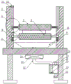
Fig. 1 is a schematic view of the overall structure of the present invention.
Fig. 2 is a schematic view of the internal structure of the present invention.
Fig. 3 is an enlarged schematic view of a portion a in fig. 1 according to the present invention.
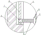
Fig. 4 is an enlarged schematic view of the structure at B in fig. 1 according to the present invention.
In the figure: 1. a support plate; 2. a first dust removal roller; 3. a second dust removal roller; 4. a first rolling shaft rod; 5. a stabilizing plate; 6. rotating the screw rod; 7. a moving ring; 8. fixing the rod; 9. a dust suction hopper; 10. a suction tube; 11. a fan; 12. a connecting pipe; 13. a direct delivery pipe; 14. a dust falling box; 15. a discharge hopper; 16. a second rolling shaft; 17. fixing the shaft lever; 18. a buffer ring; 19. a slide bar; 20. a spring; 21. a stabilizing collar; 22. rotating the cap; 23. a drain valve tube; 24. a liquid inlet hopper; 25. a support rod.
Detailed Description
In order to make the objects, technical solutions and advantages of the present invention more apparent, the present invention is described in further detail below with reference to the accompanying drawings and embodiments. It should be understood that the specific embodiments described herein are merely illustrative of the invention and are not intended to limit the invention.
In the description of the present invention, it is to be understood that the terms "length", "width", "upper", "lower", "front", "rear", "left", "right", "vertical", "horizontal", "top", "bottom", "inner", "outer", and the like, indicate orientations or positional relationships based on the orientations or positional relationships illustrated in the drawings, and are used merely for convenience in describing the present invention and for simplicity in description, and do not indicate or imply that the devices or elements referred to must have a particular orientation, be constructed in a particular orientation, and be operated, and thus, are not to be construed as limiting the present invention. Further, in the description of the present invention, "a plurality" means two or more unless specifically defined otherwise.
The textile machine textile dust collecting device shown in the attached figures 1-4 comprises a supporting plate 1, wherein the top end part of the supporting plate 1 is provided with a dust removing and collecting machine mechanism;
the dust removing and collecting mechanism comprises a first dust removing roller 2, a second dust removing roller 3 is arranged at the bottom of the first dust removing roller 2, a first rolling shaft rod 4 is arranged inside the first dust removing roller 2, stabilizing plates 5 are arranged on two sides of the top end of a supporting plate 1, an adjusting groove is formed inside the stabilizing plates 5, a rotary screw rod 6 is arranged inside the adjusting groove, a moving ring 7 is arranged outside the rotary screw rod 6, the moving ring 7 is in threaded connection with the rotary screw rod 6, one side of the moving ring 7 is fixedly connected with one end of the first rolling shaft rod 4, the first rolling shaft rod 4 is movably connected with the first dust removing roller 2, fixed rods 8 are arranged at two ends of the first rolling shaft rod 4, the fixed rods 8 are fixedly connected with the first roller, a dust suction hopper 9 is arranged at the bottom of the second dust removing roller 3, a suction pipe 10 is arranged at the bottom end of the dust suction hopper 9, a fan 11 is arranged at one end of the, the output end of the fan 11 is provided with a connecting pipe 12, one end of the connecting pipe 12 is provided with a straight conveying pipe 13, the straight conveying pipe 13 is communicated with the connecting pipe 12, a dust falling box 14 is arranged outside the straight conveying pipe 13, the dust falling box 14 is fixedly connected with the straight conveying pipe 13, one end of the straight conveying pipe 13 is provided with a discharge hopper 15, and the discharge hopper 15 is communicated with the straight conveying pipe 13.
As shown in fig. 2 and 4, a second rolling shaft rod 16 is arranged inside the second dust-removing roller 3, two ends of the second rolling shaft rod 16 are respectively provided with a fixed shaft rod 17, one end of the fixed shaft rod 17 is provided with a buffer ring 18, the buffer ring 18 is fixedly connected with the fixed shaft rod 17, a sliding rod 19 is arranged inside the buffer ring 18, the sliding rod 19 is movably connected with the buffer ring 18, the bottom end of the buffer ring 18 is provided with a spring 20, the spring 20 is fixedly connected with the buffer ring 18, so that when the spun yarn is excessively extruded, the extrusion force starts to act on the second dust-removing roller 3, the second roller starts to move downwards, then the second roller starts to drive the fixed shaft rods 17 at two sides of the second rolling shaft rod 16 to move downwards, then the fixed shaft rods 17 start to drive and the buffer ring 18 starts to move downwards on the sliding rods 19, so that the buffer ring 18 starts to extrude the spring, the spring 20 is compressed so that it acts as a buffer and does not cause excessive compression of the spun thread.
As shown in fig. 2, a fixing shaft collar 21 is disposed outside one end of the rotary screw 6, and the fixing shaft collar 21 is fixedly connected to the rotary screw 6, so that the rotary screw 6 can be fixed by the fixing shaft collar 21, and the rotary screw 6 can rotate in a bearing inside the fixing shaft collar 21 more stably.
As shown in fig. 1 and 2, a rotating cap 22 is disposed at one end of the rotating screw 6, and the rotating cap 22 is fixedly connected to the rotating screw 6, so that the rotating cap 22 is rotated to make the rotating cap 22 drive the rotating screw 6 to rotate, thereby making the rotating screw 6 start to rotate.
As shown in fig. 1 and 2, a liquid discharge valve pipe 23 is disposed at the bottom end of the dust falling box 14, and the liquid discharge valve pipe 23 is communicated with the dust falling box 14, so that sewage mixed with dust can be discharged through the liquid discharge valve pipe 23, and dust can be collected next time.
As shown in fig. 1 and 2, a liquid inlet hopper 24 is disposed at the top end of the dust falling box 14, and the liquid inlet hopper 24 is communicated with the dust falling box 14, so that water can be poured into the dust falling box 14 through the liquid inlet hopper 24 to be mixed with dust to form sewage.
As shown in fig. 1 and 2, the bottom end of the supporting plate 1 is provided with a plurality of supporting rods 25, and the supporting rods 25 are fixedly connected with the supporting plate 1, so that the supporting plate 1 can be supported by the supporting rods 25, and the supporting plate 1 is more stable and is not easy to shake.
The working principle of the invention is as follows: when in use, the spinning thread can be put between the first dust-removing roller 2 and the second dust-removing roller 3, then the rotating screw rod 6 is rotated, so that the rotating screw rod 6 starts to rotate, the moving ring 7 starts to move downwards on the rotating screw rod 6 under the action of the screw thread, then the moving wheel drives the fixed rod 8 to start to move downwards, so that the first rolling shaft lever 4 drives the first dust-removing roller 2 to start to downwards extrude the spinning thread, the spinning thread can move along with the spinning operation of the spinning thread on the spinning machine, so that the first dust-removing roller 2 is driven to start to rotate on the first rolling shaft lever 4, and the second dust-removing roller 3 also starts to roll, so that the dust on the spinning thread is cleaned, then the fan 11 is started, so that the dust-absorbing hopper 9 starts to absorb the dust into the dust-absorbing hopper 9, and then the dust-absorbing hopper 9 starts to absorb into the dust-absorbing pipe 10, inhale fan 11's input again through suction pipe 10, discharge away by fan 11's output again, then enter into connecting pipe 12, rethread connecting pipe 12 enters into straight defeated pipe 13 in, and along with suction begins to enter into through straight defeated pipe 13 and discharge and fight 15, thereby begin to discharge by discharging fighting 15 and fall in dust box 14, dust impurity forms sewage with the inside rivers of dust box 14, thereby reach the effect of removing dust, can remove dust and collect always.
The present invention is not limited to the above preferred embodiments, and any modifications, equivalent substitutions and improvements made within the spirit and principle of the present invention should be included in the protection scope of the present invention.
Claims (7)
1. A weaving machine weaving dirt collection device, includes the backup pad, its characterized in that: the top end part of the supporting plate is provided with a dust removal and collection mechanism;
the dust removal and collection mechanism comprises a first dust removal roller, a second dust removal roller is arranged at the bottom of the first dust removal roller, a first rolling shaft rod is arranged inside the first dust removal roller, stabilizing plates are arranged on two sides of the top end of the supporting plate, an adjusting groove is formed in the stabilizing plates, a rotary screw rod is arranged in the adjusting groove, a moving ring is arranged outside the rotary screw rod and is in threaded connection with the rotary screw rod, one side of the moving ring is fixedly connected with one end of the first rolling shaft rod, the first rolling shaft rod is movably connected with the first dust removal roller, fixing rods are arranged at two ends of the first rolling shaft rod and are fixedly connected with the first roller, a dust suction hopper is arranged at the bottom of the second dust removal roller, a suction pipe is arranged at the bottom end of the dust suction hopper, a fan is arranged at one end of the suction pipe, and two ends of the suction pipe are respectively and fixedly connected with the dust suction hopper, the fan is characterized in that a connecting pipe is arranged at the output end of the fan, a straight conveying pipe is arranged at one end of the connecting pipe and is communicated with the connecting pipe, a dust falling box is arranged outside the straight conveying pipe and is fixedly connected with the straight conveying pipe, and a discharge hopper is arranged at one end of the straight conveying pipe and is communicated with the straight conveying pipe.
2. A textile machine dust collecting device as claimed in claim 1, wherein: the second dedusting roller is internally provided with a second rolling shaft rod, two ends of the second rolling shaft rod are respectively provided with a fixed shaft rod, one end of the fixed shaft rod is provided with a buffering ring, the buffering ring is fixedly connected with the fixed shaft rod, a sliding rod is arranged inside the buffering ring and is movably connected with the buffering ring, the bottom end of the buffering ring is provided with a spring, and the spring is fixedly connected with the buffering ring.
3. A textile machine dust collecting device as claimed in claim 1, wherein: and a stabilizing shaft collar is arranged outside one end of the rotary screw rod and is fixedly connected with the rotary screw rod.
4. A textile machine dust collecting device as claimed in claim 1, wherein: and a rotary cap is arranged at one end of the rotary screw rod and is fixedly connected with the rotary screw rod.
5. A textile machine dust collecting device as claimed in claim 1, wherein: and a liquid discharge valve pipe is arranged at the bottom end of the dust falling box and communicated with the dust falling box.
6. A textile machine dust collecting device as claimed in claim 1, wherein: and a liquid inlet hopper is arranged at the top end of the dust falling box and communicated with the dust falling box.
7. A textile machine dust collecting device as claimed in claim 1, wherein: the bottom end of the supporting plate is provided with a plurality of supporting rods, and the supporting rods are fixedly connected with the supporting plate.
Priority Applications (1)
| Application Number | Priority Date | Filing Date | Title |
|---|---|---|---|
| CN202011548823.XA CN112553725A (en) | 2020-12-24 | 2020-12-24 | Weaving machine weaving dirt collection device |
Applications Claiming Priority (1)
| Application Number | Priority Date | Filing Date | Title |
|---|---|---|---|
| CN202011548823.XA CN112553725A (en) | 2020-12-24 | 2020-12-24 | Weaving machine weaving dirt collection device |
Publications (1)
| Publication Number | Publication Date |
|---|---|
| CN112553725A true CN112553725A (en) | 2021-03-26 |
Family
ID=75033220
Family Applications (1)
| Application Number | Title | Priority Date | Filing Date |
|---|---|---|---|
| CN202011548823.XA Pending CN112553725A (en) | 2020-12-24 | 2020-12-24 | Weaving machine weaving dirt collection device |
Country Status (1)
| Country | Link |
|---|---|
| CN (1) | CN112553725A (en) |
Cited By (1)
| Publication number | Priority date | Publication date | Assignee | Title |
|---|---|---|---|---|
| CN115029825A (en) * | 2022-07-28 | 2022-09-09 | 桐乡市信逸纺织科技有限公司 | Add high-efficient wire guide of bullet machine |
Citations (11)
| Publication number | Priority date | Publication date | Assignee | Title |
|---|---|---|---|---|
| US20070272360A1 (en) * | 2006-05-25 | 2007-11-29 | Airbus Espana, S.L. | Cleaning device for a preimpregnated carbon fiber placement machine |
| DE102006035729A1 (en) * | 2006-07-28 | 2008-01-31 | Maschinenfabrik Rieter Ag | Device for the suction and filtration of dust- and/or fiber loaded air on spinning machines, comprises working places having suction channel, filtering device with filter, removal system, operating means and vacuum source and -sensor |
| CN101466882A (en) * | 2006-06-09 | 2009-06-24 | 株式会社岛精机制作所 | Cleaner device of splicer device |
| CN208246652U (en) * | 2018-06-08 | 2018-12-18 | 福建祥源纺织有限公司 | A kind of cloth production clamps the clamping and pressing device of thickness with adjustable workpiece |
| CN208803281U (en) * | 2018-08-31 | 2019-04-30 | 杭州布调科技有限公司 | A kind of textile process fabric dust exhaust apparatus |
| CN210974963U (en) * | 2019-08-07 | 2020-07-10 | 青岛中久美工贸有限公司 | Dust collector for carding machine |
| CN211522626U (en) * | 2019-10-25 | 2020-09-18 | 湖北妙虎纺织有限责任公司 | Weaving machine weaving dirt collection device |
| CN211812541U (en) * | 2020-02-24 | 2020-10-30 | 浙江昕欣数码科技股份有限公司 | Continuous coiling mechanism of textile printing and dyeing |
| CN111850912A (en) * | 2020-07-22 | 2020-10-30 | 谷东虎 | Roll-in system of home textile fabric |
| CN211936165U (en) * | 2019-12-20 | 2020-11-17 | 际华三五零九纺织有限公司 | Weaving machine weaving dirt collection device |
| CN212049704U (en) * | 2020-03-10 | 2020-12-01 | 吴江市欧鑫纺织品有限公司 | Prevent chaotic batching equipment for textile processing |
-
2020
- 2020-12-24 CN CN202011548823.XA patent/CN112553725A/en active Pending
Patent Citations (11)
| Publication number | Priority date | Publication date | Assignee | Title |
|---|---|---|---|---|
| US20070272360A1 (en) * | 2006-05-25 | 2007-11-29 | Airbus Espana, S.L. | Cleaning device for a preimpregnated carbon fiber placement machine |
| CN101466882A (en) * | 2006-06-09 | 2009-06-24 | 株式会社岛精机制作所 | Cleaner device of splicer device |
| DE102006035729A1 (en) * | 2006-07-28 | 2008-01-31 | Maschinenfabrik Rieter Ag | Device for the suction and filtration of dust- and/or fiber loaded air on spinning machines, comprises working places having suction channel, filtering device with filter, removal system, operating means and vacuum source and -sensor |
| CN208246652U (en) * | 2018-06-08 | 2018-12-18 | 福建祥源纺织有限公司 | A kind of cloth production clamps the clamping and pressing device of thickness with adjustable workpiece |
| CN208803281U (en) * | 2018-08-31 | 2019-04-30 | 杭州布调科技有限公司 | A kind of textile process fabric dust exhaust apparatus |
| CN210974963U (en) * | 2019-08-07 | 2020-07-10 | 青岛中久美工贸有限公司 | Dust collector for carding machine |
| CN211522626U (en) * | 2019-10-25 | 2020-09-18 | 湖北妙虎纺织有限责任公司 | Weaving machine weaving dirt collection device |
| CN211936165U (en) * | 2019-12-20 | 2020-11-17 | 际华三五零九纺织有限公司 | Weaving machine weaving dirt collection device |
| CN211812541U (en) * | 2020-02-24 | 2020-10-30 | 浙江昕欣数码科技股份有限公司 | Continuous coiling mechanism of textile printing and dyeing |
| CN212049704U (en) * | 2020-03-10 | 2020-12-01 | 吴江市欧鑫纺织品有限公司 | Prevent chaotic batching equipment for textile processing |
| CN111850912A (en) * | 2020-07-22 | 2020-10-30 | 谷东虎 | Roll-in system of home textile fabric |
Cited By (1)
| Publication number | Priority date | Publication date | Assignee | Title |
|---|---|---|---|---|
| CN115029825A (en) * | 2022-07-28 | 2022-09-09 | 桐乡市信逸纺织科技有限公司 | Add high-efficient wire guide of bullet machine |
Similar Documents
| Publication | Publication Date | Title |
|---|---|---|
| CN108035133A (en) | One kind removal of impurities cleaner | |
| CN208136442U (en) | A kind of textile machines have heat dissipation and dedusting function device | |
| CN108660593A (en) | A kind of textile machines have heat dissipation and dedusting function device | |
| CN107823984A (en) | A kind of weaving loom weaving dirt collection device | |
| CN105063814A (en) | Dust sucking device for cotton carding machine | |
| CN102191589A (en) | Seed-cotton foreign fiber cleaning machine | |
| CN112553725A (en) | Weaving machine weaving dirt collection device | |
| JP7102628B2 (en) | Dust removal equipment for spinning equipment | |
| CN213538217U (en) | A weaving dirt collection device for weaving processing | |
| CN108744776A (en) | A kind of textile machines weaving dirt collection device | |
| CN204051258U (en) | A kind of clear assorted type deduster automatically | |
| CN216074133U (en) | Cotton yarn weaving carding equipment | |
| CN104357960A (en) | Improved airflow type lint cleaning machine | |
| CN212121070U (en) | Textile waste collection device | |
| CN210066023U (en) | Dust collector is used in yarn production | |
| CN209144337U (en) | A kind of efficient impurity removal carding machine | |
| CN210560953U (en) | Twisting machine for producing fishing net thread and convenient to clean and refuel | |
| CN209576119U (en) | A kind of dust-extraction unit of Knitting Machinery | |
| CN213942484U (en) | A dust storage device for weaving factory removes dust | |
| CN102618971A (en) | Cage type cotton removing and tiny dust removing machine | |
| CN206843666U (en) | One kind repairs easily weaving loom dust exhaust apparatus | |
| CN220099342U (en) | Automatic dust removing mechanism of circular knitting machine | |
| CN217104181U (en) | Cleaning device for carding machine | |
| CN215366135U (en) | Spinning frame for spinning production of bicomponent yarn | |
| CN218026495U (en) | Weaving comb and parallel cotton fibers prior to spinning device with protective structure |
Legal Events
| Date | Code | Title | Description |
|---|---|---|---|
| PB01 | Publication | ||
| PB01 | Publication | ||
| SE01 | Entry into force of request for substantive examination | ||
| SE01 | Entry into force of request for substantive examination | ||
| RJ01 | Rejection of invention patent application after publication |
Application publication date: 20210326 |
|
| RJ01 | Rejection of invention patent application after publication |